Week 5 Bending of iPhone
Simulation of bending of iPhone:
Aim:
Bending of iPhone frame & display challenge is performed taking different materials & their properties mentioned in the cases below.
Steps followed:
Case 1:
1) Material selection:
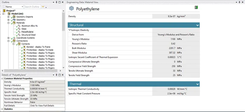
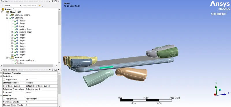
a)Polyethylene:Polyethylene is selected in Engineering data from the list of General materials, for the interior of iPhone were motherboard and all other electronic components are present.
Material specification of Polyethylene shown in the image below:
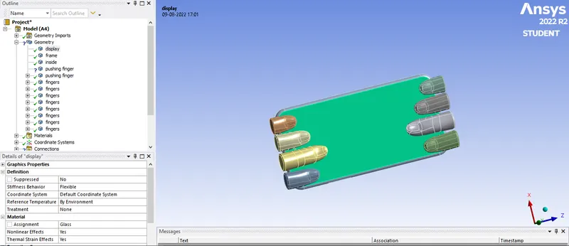
b)Glass:Glass is chossen for the Display of iPhone after Duplicating Polyethylene already selected in Engineering Data with the material specifications shown in the image below: 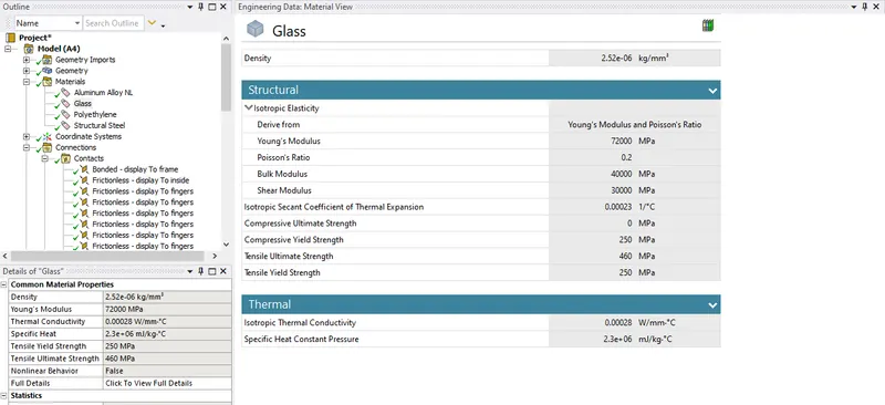
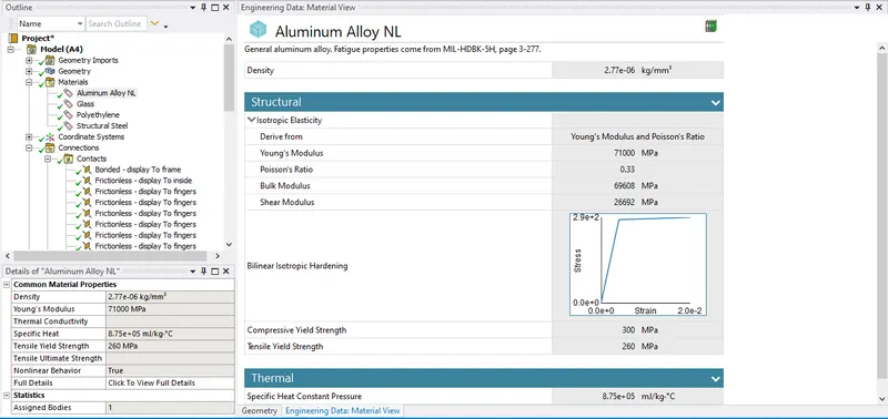
c)Aluminium Alloy NL:Aluminium Alloy NL is taken from General Non linear elements list from engineering data for the Frame of iPhone with material specifications shown in the image below:
2)Geometry:
3)Modelling:
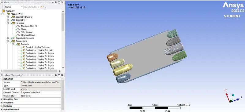
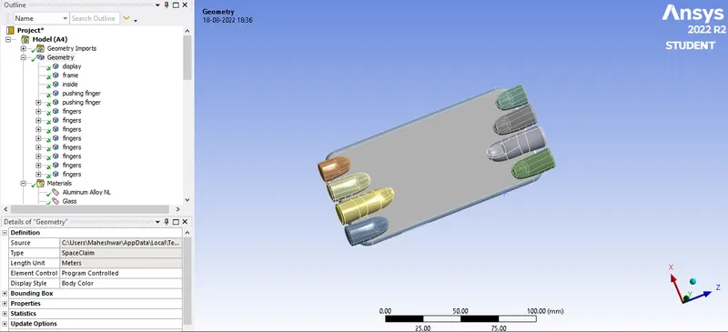
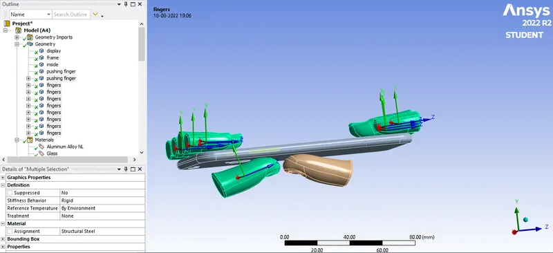
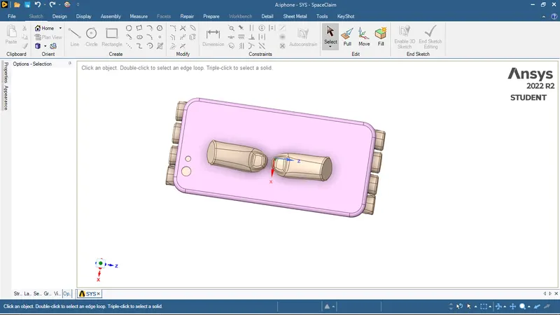
Open the Model from main menu bar & click on the + sign beside Geometry option & Rename the first 3 part as Display, Frame and Inside by selecting them and changing their material as Glass,Aluminium Alloy NL & Polyethylene respectively.
The two thumbs shown below are named as Pushing Finger while rest are named as Fingers
Glass for Display of iPhone:
Polyethylene for Inside of iPhone:
Rest parts are named as Pushing Finger and Finger:
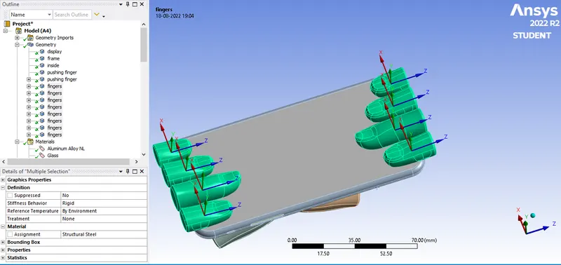
Select from the downward pushing finger and make Stiffness Behaviour as Rigid.
4)Connections & Joints:
Contacts: Select Contacts from Connections and delete the last two contacts between the 2 fingers which contain '?' symbol beside them.
Select all the contacts with Shift key & right click & select Rename Based on Defination.
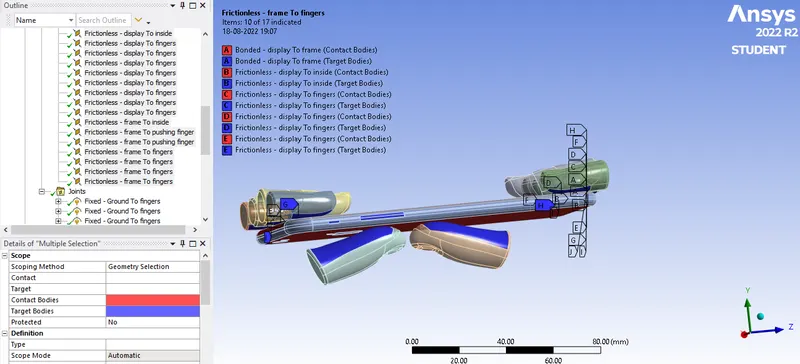
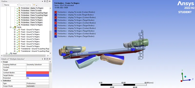
Other than "Display to Frame" contact select the rest with Type Frictionless.
While that of Display to Frame has Bonded Type contact.
Image below shows all the contact settings:
Joints:
Right click on Connections & insert Joints.Apply Body-Ground as Connection-Type of joint for the 8 fingers holding the iPhone at top face as Fixed Joint & select 8 fingers each at a time by Box Select option by hiding all other parts respectively for each of 8 fingers at the top.
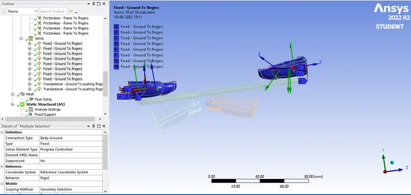
For the two Thumbs at the bottom,Select each by Box select same as above with Connection type Body-Ground but this time Joint Type is Translational for 2 thumbs.
Select the the Translational joint with Pushing Finger which is downward to make the X axis of both Pushing Finger Translational Joint upward by selecting within Principal Axis-Defin By:Global Y axis to make both the axis of X upward.
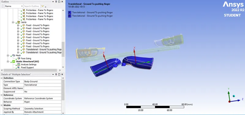
5)Meshing:
Insert Face sizing between Pushing Finger (Thumbs) face & bottom face of the Frame to 3mm.
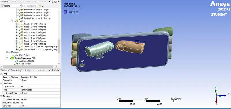
Mesh Quality Smoothing is choosen as low.
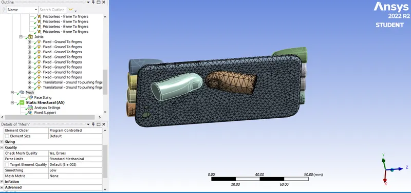
Meshing:
6)Boundary canditions:
a)Analysis Settings:
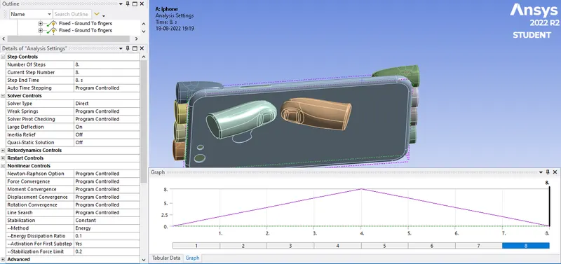
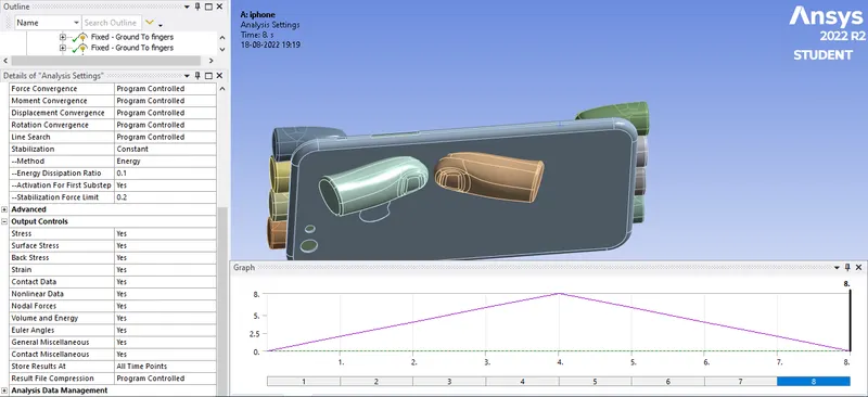
Number of steps taken for analysis was 8 with Solver type:Direct and Weak Springs:Programme Controlled.Large Deflections are switched On and within Non-Linear controls Stablization as Constant with Energy Dissipation as 0.1 and Activation for the first substep selected as Yes and all Output controls changed to Yes.
b)Fixed Support:
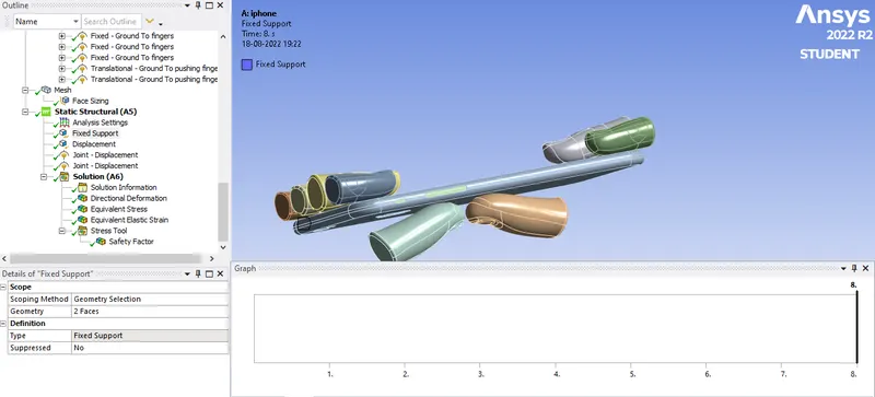
Fixed support is applied to make sure that iPhone does not move apart when the loads are applied for bending it by selecting the faces of inside body.
c)Displacement:
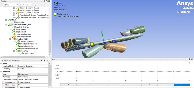
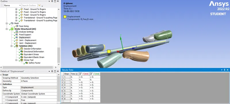
A displacement is inputed on the face of frame along Y axis so X and Z axis are kept at 0 constant.
d)Joint Displacement:
Joint Displacement was applied on the joint of Ground to pushing fingers by selecting Thumbs bascially in a Tabular data as shown below:
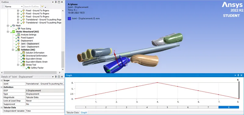
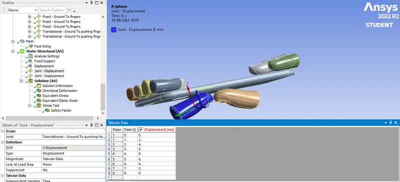
Displacement vs Step graph:
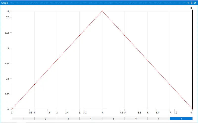
It is clearly seen from the above graph that Maximum displacement of 8mm applied at the 4th step.
Case 2:
All the steps followed were same as above 6 only 2 additional steps were taken
- Aluminium Alloy NL selected for frame material is given S-N curve input in Engineering data during material selection as per the data mentioned above.
Aluminum Alloy NL with S-N curve:
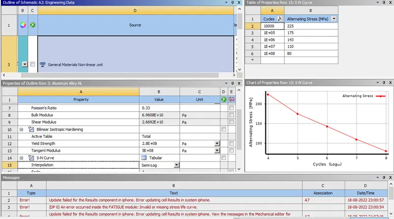
Pushing Finger or Bottom fingers are moved to along X=22.5mm & along Z=10mm both resulting in new Geometry & new postion of loads.
Results:
Case 1:
Directional Deformation:
Directional Deformation takes place along Y axis with respect to Displacement applied.
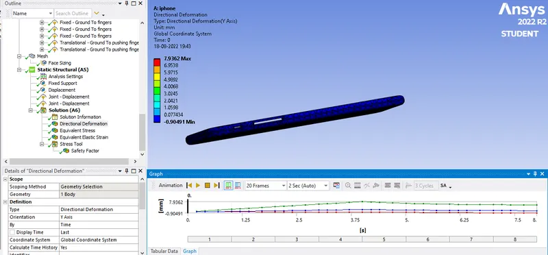
Maximum Directional deformation along Y acts on the frame:7.94mm
Factor of Safety:
Factor of safety indicates how much applied loads are safe for a given material with respesct to its Yield or Ultimate Strength.
Here factor of safety for Aluminum Alloy NL is taken for Frame of iPhone.
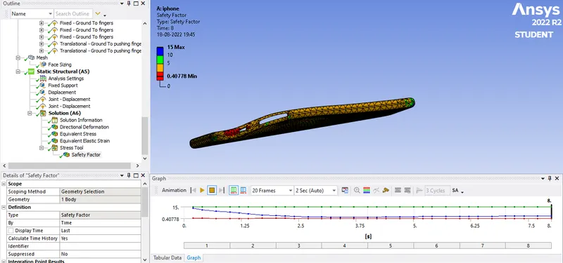
Minimum Factor of Safety for Aluminium Alloy NL frame of iPhone:0.40778
Equivalent Stress for Aluminium alloy NL Frame:
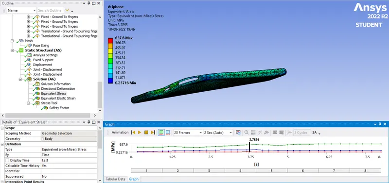
Maximum Equivalent Stress for the Aluminium alloy NL frame of iPhone during bending:637.6 MPa
Case 2:
Directional Deformation:
Directional Deformation takes place along Y axis with respect to Displacement applied.
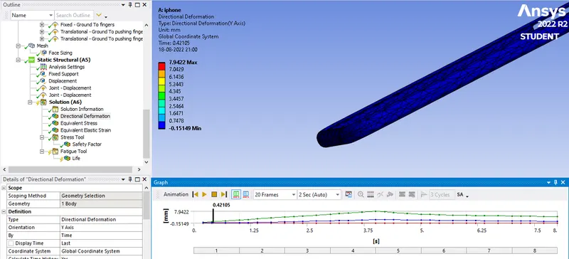
Maximum Directional deformation along Y acts on the frame:7.9422 mm
Factor of Safety:
Factor of safety indicates how much applied loads are safe for a given material with respesct to its Yield or Ultimate Strength.
Here factor of safety for Aluminum Alloy NL is taken for Frame of iPhone.
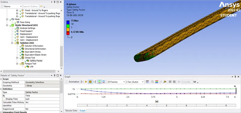
Minimum Factor of Safety for Aluminium Alloy NL frame of iPhone:0.7283
Equivalent Stress for Aluminium alloy NL Frame:
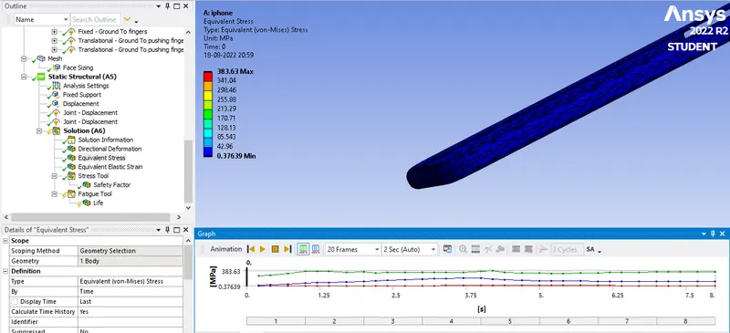
Maximum Equivalent Stress for the Aluminium alloy NL frame of iPhone during bending:383.63MPa
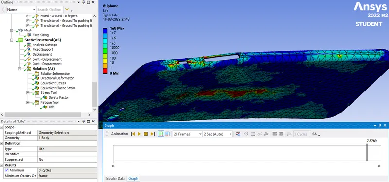
Fatigue Life for Aluminium alloy NL frame of iPhone:
Comparision:
Maximum Y-Directional Deformation,Minimum Factor of Safety & Maximum Equivalent stress for Aluminum Alloy NL Frame was taken for comparision in table below for both the cases.
| Case | Maximum Y-Directional Deformation(mm) | Minimum Factor of Safety | Maximum Equivalent stress(MPa) |
| 1 | 7.94 | 0.40778 | 637.6 |
| 2 | 7.9422 | 0.7283 | 383.63 |
Conclusion:
- Maximum Directional deformation on Frame of Aluminium Alloy NL for both the case occurs along Y axis of 8mm.
- Highest Maximum Equivalent stress occurs in case 1 as in case 2 bottom or pushing fingers are at centre and loads are uniformly distributed during bending.
- It can be seen from the table above that Factor of Safety for both Case 1 & Case 2 are less than 1 so both will fail and such high loads & displacement inout must be avoided.
i cannot upload the ansys wbpz as the file size is 200mb