Week 5 Bending of iPhone
Bending of iPhone
OBJECTIVE:-
To simulate the bending of the IPhone as per the given cases below.
Case 1: Simulate the model without any change in the pushin fingers position
Case 2: Move the bottom fingers from their defined position to the given position X= 22.5mm & Z= 10mm and obtain the results for the simulation. Also define the S-N curve for the Aluminium Alloy material as per values given below and determine the fatigue life results for the same.
| Stress, MPa | Number of Cycles, N |
| 225 | 10000 |
| 175 | 100000 |
| 143 | 1000000 |
| 110 | 10000000 |
| 80 | 100000000 |
INTRODUCTION:-
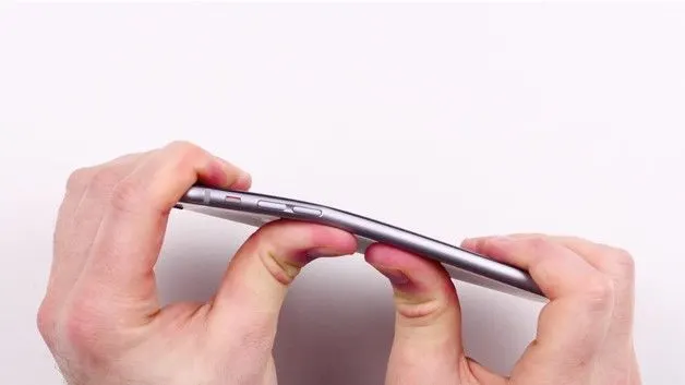
The iPhone is a smartphone made by Apple that combines a computer, iPod, digital camera and cellular phone into one device with a touchscreen interface. The iPhone runs the iOS operating system (OS), and as of 2017, there were 2.2 million apps available for it through the Apple App Store, according to Statista. The iPhone 6, particularly the iPhone 6 Plus, was the subject of many criticisms and jokes when it was discovered to bend almost too easily to pressure applied by nothing more than regular hands or placing them in the back pockets of tight jeans and sitting in different angles repeatedly.
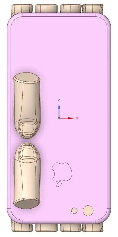
There are a number of reports claiming that the iPhone bends inside of people's pockets. Some speculate that the tightness of your pants is significant here. The tighter they are, the more pressure they exert on your phone. It seems clear, too, that a lot depends on whether you lean forward when you sit or maintain a more correct upright position. Some say that extra-tight jeans are to blame, but it's really an issue of building materials the iPhone 6 and 6+ feature an aluminum chassis spread over a wider area than any previous iPhone. Aluminum is a naturally soft metal; with enough pressure and leverage, it's going to bend. In this project, an iPhone model is made to bend using thumb fingers placed just below the volume button and in the next case, the thumb fingers are placed at the middle of the bottom side of the phone.
PROCEDURE:-
Case-1:-
1) Material-
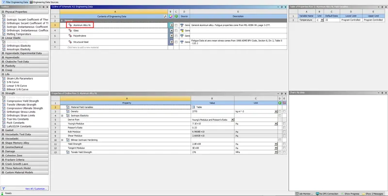
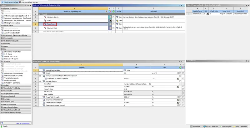
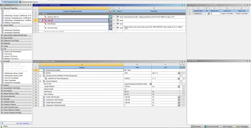
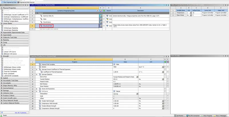
We have to add material first of all for simulation setup and here Alluminium alloy NL material is added from General Non-Linear Material, Polyethylene material is added from General Materials and Glass material is created by duplicating the Polyethylene material and entering all the parameter values manually.
2) Geometry-
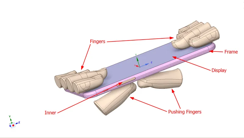
Import the geometry in SpaceClaim. The given 3D model of iPhone bending assembly is imported into SpaceClaim. The iPhone assembly consists of display, frame, inside parts, pushing fingers and supporting fingers.
3) Rename and Material assignment-
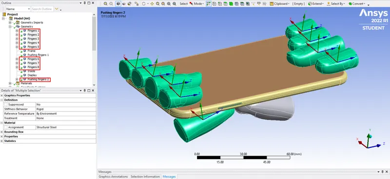
Open the model in ANSYS Mechanical and rename all the components. There are 8 fingers, 2 pushing fingers, 1 display, 1 inner, 1 frame in the whole model. Alluminium Alloy NL is assigned for frame, Polyethylene is assigned to inner, Glass is assigned to display and Structural Steel is assigned to all the fingers.
Change Stiffness Behaviour as Rigid for all the fingers and one pushing fingers because deformation of these components can not be allowed so that the phone can be bent against these fingers.
4) Contacts-
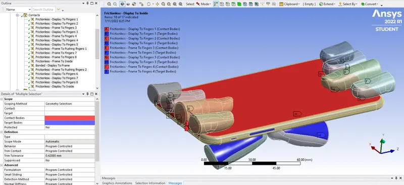
Delete contacts between fingers because those are not required. Select all the contacts, right click and chose Rename Based on Definition option. Contact between, (a) display and frame is assigned as bonded contact and (b) display and fingers are assigned as frictionless contact.
5) Joints-
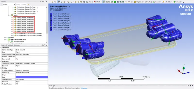
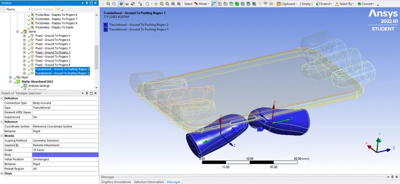
Define fixed joints for all the fingers and Translational joints for all the pushing fingers. The fixed type of joint is assigned for supporting fingers to hold the display with connection type being body-ground. The translational type of joint is assigned for both pushing fingers with connection type being body-ground, since the pushing fingers has to move upward in order to bend the iPhone.
6) Meshing-
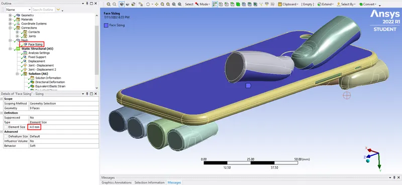
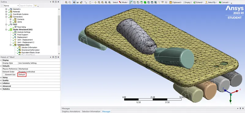
The element size of bottom surface of frame and contact surface of pushing fingers is set as 4 mm using face sizing option and other components are meshed with default element size. The total number of nodes and elements generated are 23270 and 10944 respectively.
7) Analysis Settings-
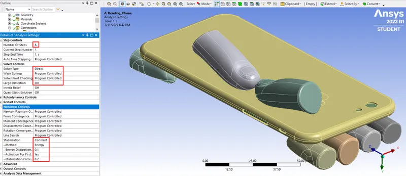
In the analysis settings the number of steps considered is 8. In solver controls, the solver type selected is ‘Direct’, with weak spring set as ‘Program controlled’ and large deflection is set to ‘On’. Under the nonlinear controls, the stabilization is set as constant with energy dissipation ratio being ‘0.1’ and activation for first sub-step set as ‘Yes’.
8) Fixed Supports-
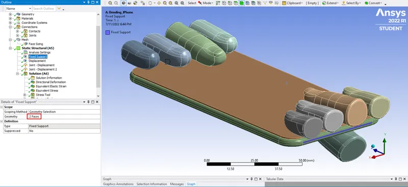
Fixed supports are provided to 2 of the faces of the inner components to keep it stationary so that it doesn't fly off during the simulation.
9) Displacements-
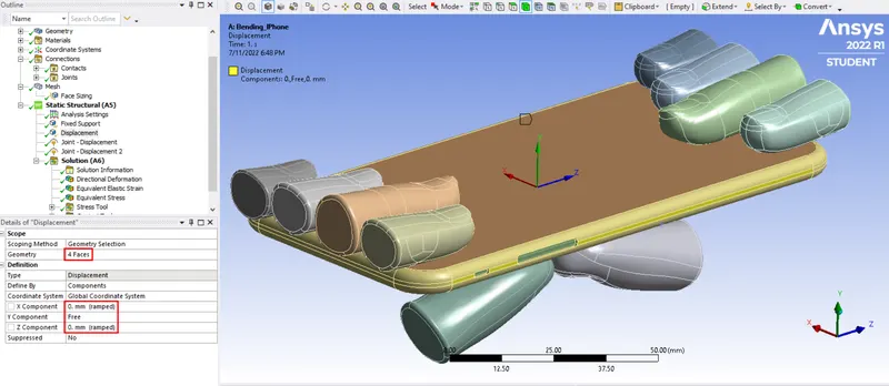
In order to move the iPhone in upward Y-direction while pushing, the displacement is set to free in Y-direction and constrained in other directions.
10) Joint Load-
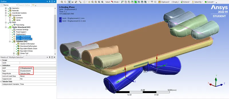
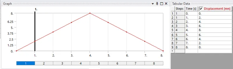
Displacement joint load is defined for both the pushing fingers in X direction of respective Reference Coordinate Systems already defined in Translational joint created while defining joint for the pushing fingers.
11) Results Requested-
Results and Discussions-
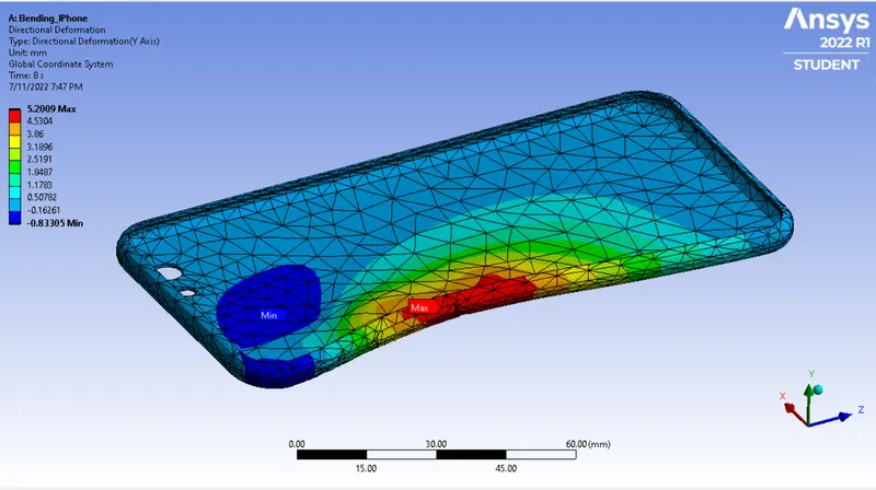
Directional Deformation in the Y-axis (Frame):
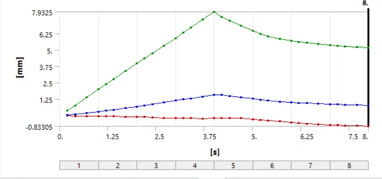
The maximum deformation of frame along Y-axis reaches a maximum of 7.9325 mm at the lower side of hole region for side button and reduces as the load is removed and reaches to a value of 5.2009 mm at the end of step 8. Hence, it is observed from plot that the frame deforms plastically and does not regain its original shape and position.
Equivalent (v-m) Stress in Frame:
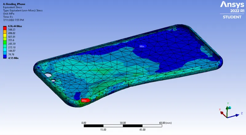
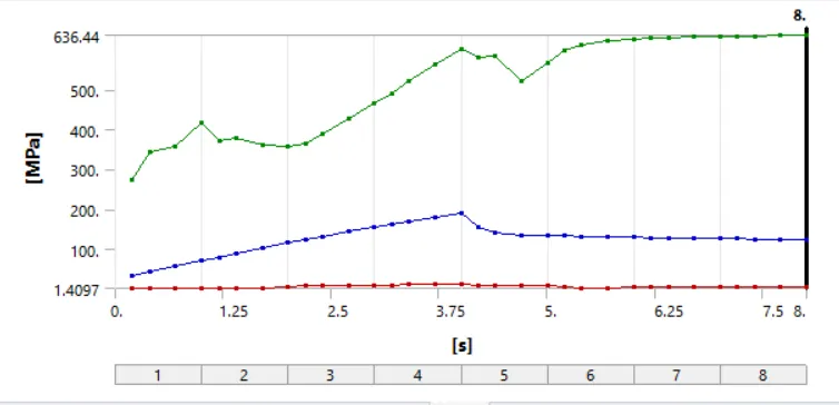
The maximum v-m stress developed in frame is 636.44 MPa near the hole region for side button.
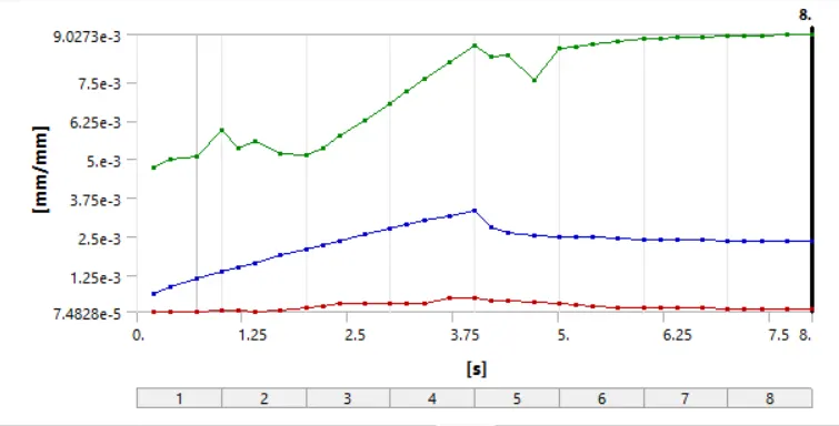
Equivalent Elastic Strain in Frame:
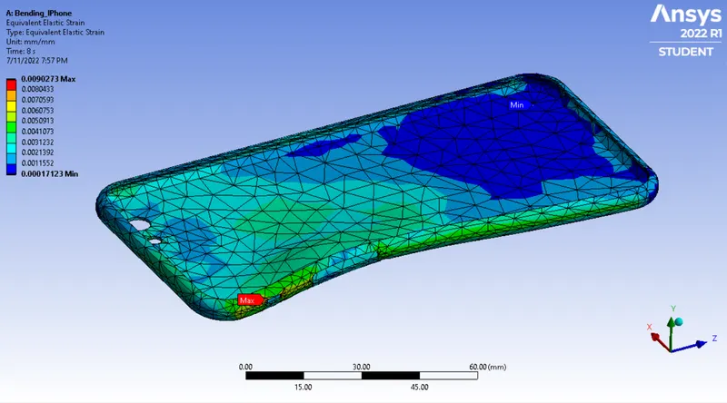
The maximum equivalent elastic strain developed in frame is 0.0090273 near the hole region for side button.
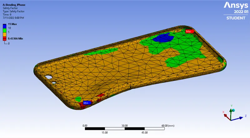
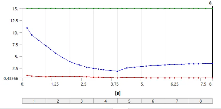
Safety Factor of Frame:
The max. safety factor for the aluminum alloy NL material of frame is 15 and min. is 0.27695, which is less than 1 hence material cannot sustain the applied load and eventually leads to failure.
Case-2:-
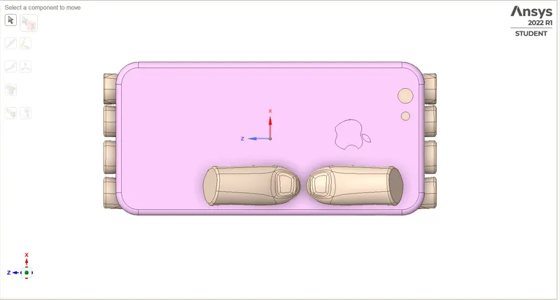
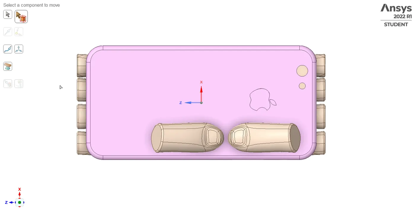
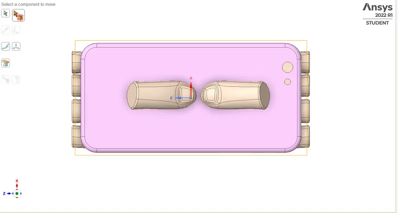
In this case some modifications are done in Engineering material section for Alluminium Alloy NL material which was assigned to the frame and also position of pushing fingers are changed as per mentioned in the objective which is X=22.5mm and Z=10mm. all the others paremeters are kept same as the Case-1 except for requesting the result regarding fatigue life of the frame when bent-
A new parameter S-N Curve is included for this material to get Fatigue life cycle as simulation results for the frame when bent and S-N curve is defined by entering values given in objective in the S-N Curve table.
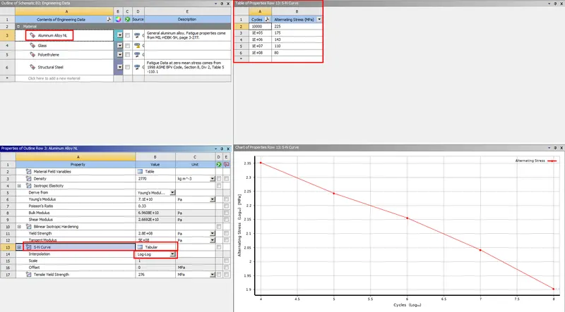
Pushing fingers were moved in Z direction by 10mm and in X direction by 22.5mm as shown in the image below.
Results and Discussions-
Directional Deformation in the Y-axis (Frame):
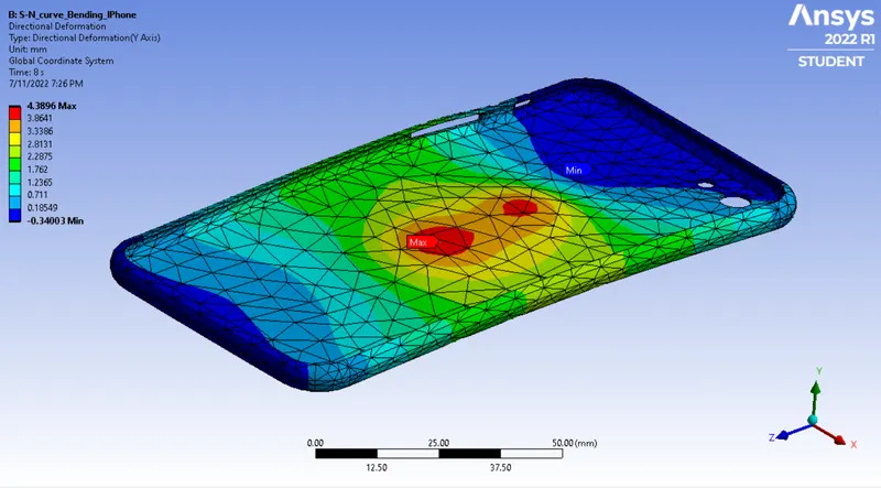
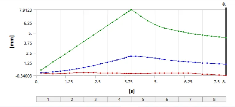
The maximum deformation of frame along Y-axis reaches a maximum of 7.9123 mm at the middle and reduces as the load is removed and reaches to a value of 4.3896 mm at the end of step 8. Hence, it is observed from plot that the frame deforms plastically and does not regain its original shape and position.
Equivalent (v-m) Stress in Frame:
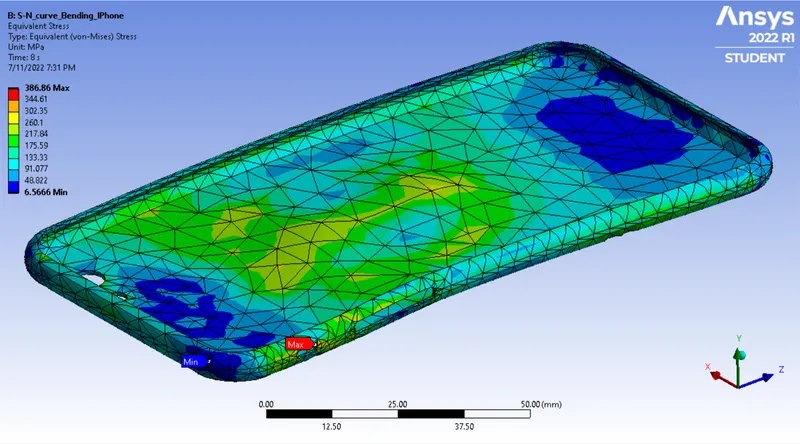
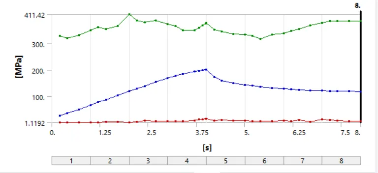
The maximum v-m stress developed in frame is 441.42 MPa near the hole region for side button.
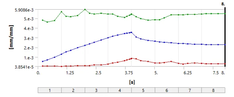
Equivalent Elastic Strain in Frame:
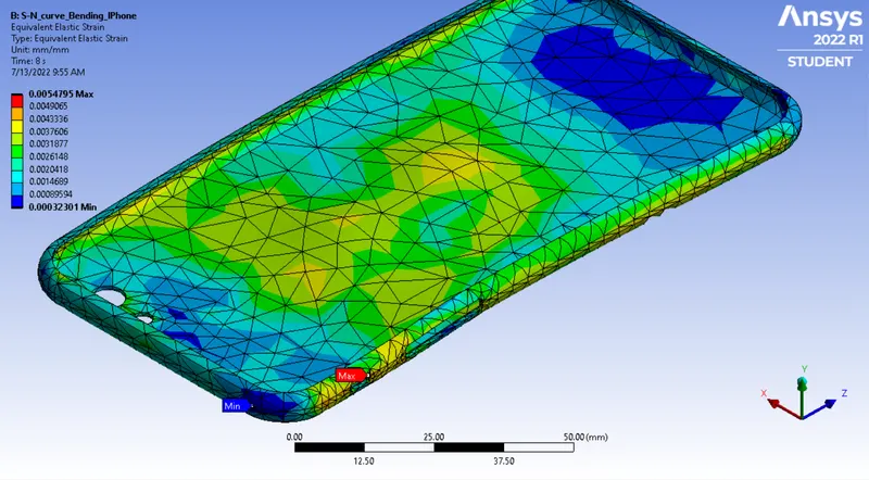
The maximum equivalent elastic strain developed in frame is 0.0059086 near the hole region for side button.
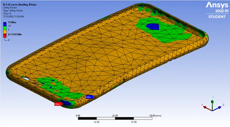
Safety Factor of Frame:
The fatigue safety factor for the aluminum alloy NL material of frame is 0.71343, which is less than 1, hence material cannot sustain the applied load and eventually leads to failure.
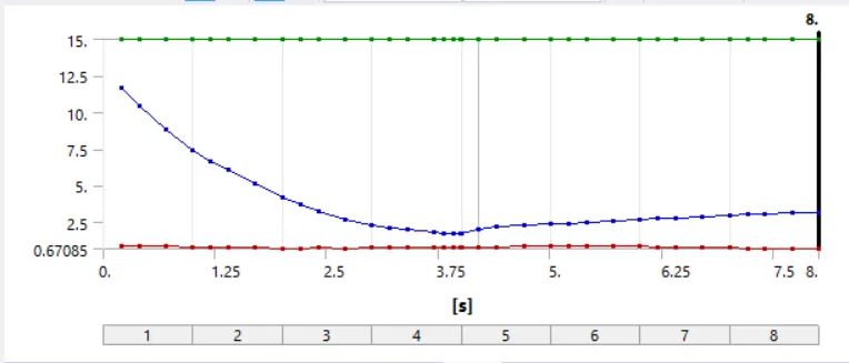
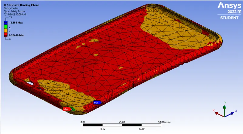
Fatigue Safety Factor of Frame:
The min. fatigue safety factor for the aluminum alloy NL material of frame is 0.20679.
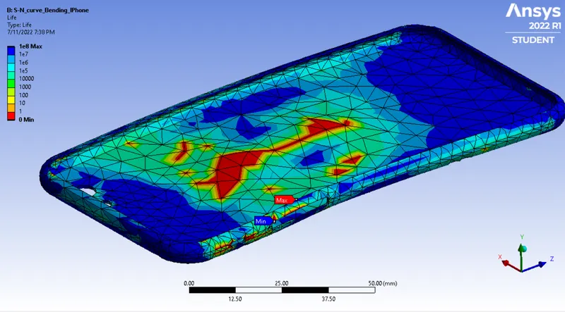
Fatigue Life of Frame:
The maximum fatigue life of frame is 1e8 cycles.
Comparision:-
| Cases | Directional deformation in Y-axis, mm | Max. Equivalent stress, MPa | Max. Equivalent elastic strain | Min. Safety factor | Min. Fatigue safety factor | Max. Fatigue life, Cycles |
| Case-1 | 7.9325 | 636.44 | 0.0090273 | 0.27695 | - | - |
| Case-2 | 7.9123 | 441.42 | 0.0059086 | 0.71343 | 0.20679 | 1.00E+08 |
CONCLUSIONS:-
1) Simulation of IPhone bending was carried out successfully for the following case study,
- Case 1 - Bottom fingers in their pre-defined position.
- Case 2 - Bottom fingers moved from their defined position to the given position X= 22.5mm & Z= 10mm.
2) The values of max. deformation along Y-axis, equivalent stress and equivalent elastic strain for case 1 is more compared to case 2, because the load applied through pushing fingers for case 2 is at the middle of frame and in the case 1, the load is applied at the edge of the IPhone frame.
3) The minimum fatigue safety factor for aluminum alloy NL material of frame is less than 1, hence material cannot sustain the applied load and eventually leads to failure.