Week 5 Battery characteristics using drive cycle
Aim:
To Simulate generic battery model charge discharge using UDDS data.
Procedure:
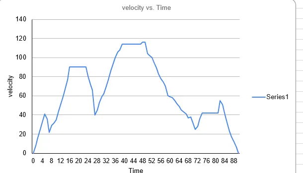
* UDDS Drive cycle:
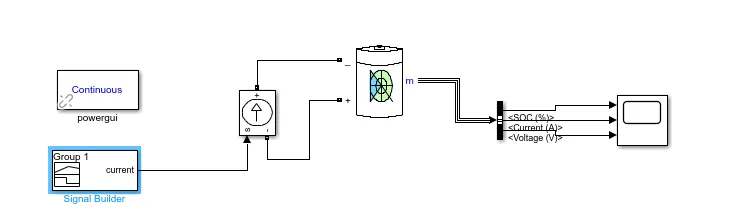
Simulink Model:
i) Signal builder:
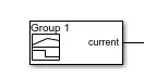
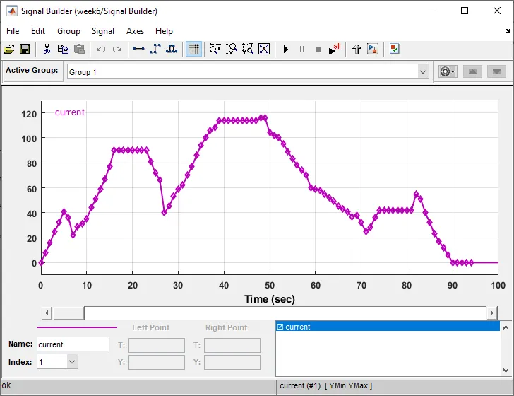
* The Signal builder displays,creates,edits the interchangable scenarios.
* The Signal builder supports the MAT files that contains one or more data projects.
* By Using this Block, we can give UDDS cycle, which is being imported and given as Input
ii) Controlled Current Source:

* The Controlled Current Source controls the Simulink input signal to an equivalent current source.
* The generated current is driven by input signal of the block.
* You can initialize the Controlled with the AC or DC current.
iii) Generic Battery Source:
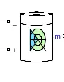
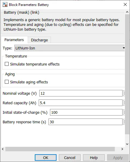
This represents that the generic dynamic model that represents the most types of rechargeable batteries.
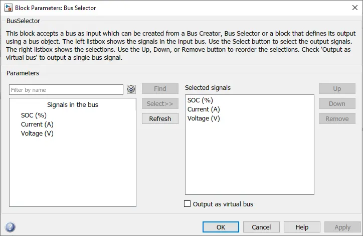
iv) Bus Selector:

* The bus selector outputs the element which is selected from the input bus.
* The block output can be selected elements that can be separately in a new virtual bus.
v) Scope:
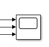
* The scope displays its inputs with respect to simulation time.
* The scope block can have multiple axes, which are independent to the y-axes.
* Allows to display and adjust the amount of time amd range of input values displayed.
vi) Power gui:
* The powergui block is necessary for simulation of any SIMULATION block of any Simulink model containing SimPowerSystems blocks.
* Used to store the Simulink circuit that represent the state-space equation of the model.
Observation:
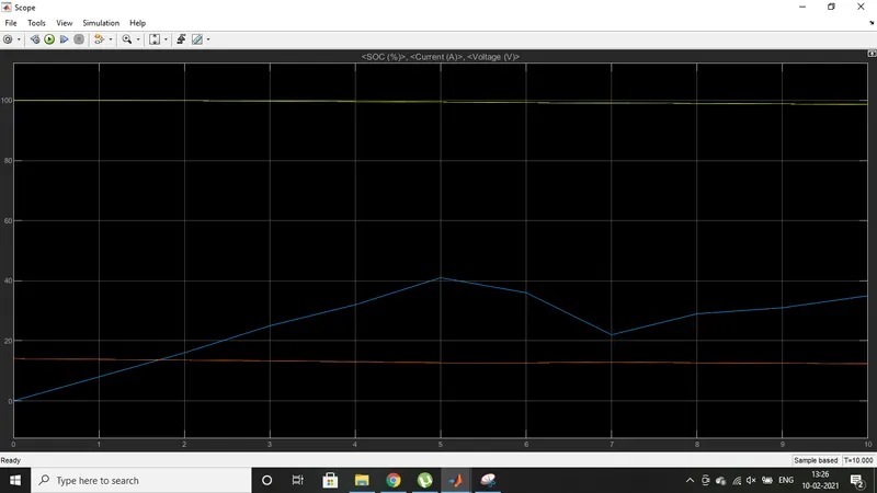
* From this scope, the Battery SOC is becoming up and down, according to the charging and discharging of the battery.
* The negative current means the charging and the positive current means discharging in the terms of battery.
Result:
The Simulation of generic battery model charge discharge using UDDS data has been done, using SIMULINK software.