Week 5.3 - Forced convection Analysis
JORGE LOZANO
Electronic Cooling Simulations using ANSYS ICEPAK
Forced Convection Analysis
In this challenge, Students should create the workflow in Ansys workbench and use the simplified geometry of DME assembly provided and solve them for physics.
Process
As in every workspace simulation in Ansys, the first step is to open and analyze the enclosure volume and the assemblies that could be created obtaining a mesh wise benefit.
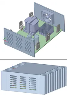
The following step involves determining every part into a ICEPAK object and determining every individual part into a simplified geometry for the optimized simulation assembly.
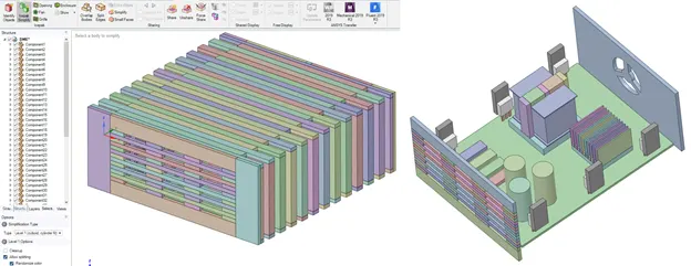
Once opened in the ICEPAK software, the cabinet will be modified into the right ideal geometrical conditions, having an all-collapsed assembly as well.
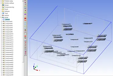
It can be possibly to thee all individual geometries by selection all expand selection in the tree assembly.
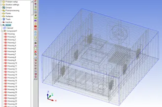
Due to the nature of the simulation, an ideal fan must be generated in the wall surface of the enclosure with an intake 0.1 m/s condition,
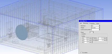
The mesh generated is a default conditions mesh, seeing all bleeding happening in the refined parts as seen in the following image.
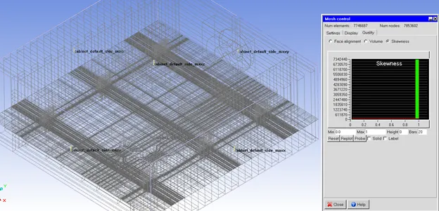
By creating subassemblies it’s possible to reduce the bleeding effect in the mesh and the cell count still maintaining a good skewness quality factor.
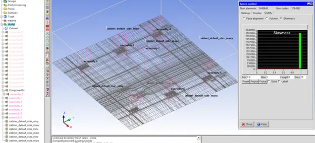
By performing a local mesh in every subassembly selected and determining a factor of each according to the geometry complexity, it was able to reduce a cell count of 551,016, with a great mesh quality.
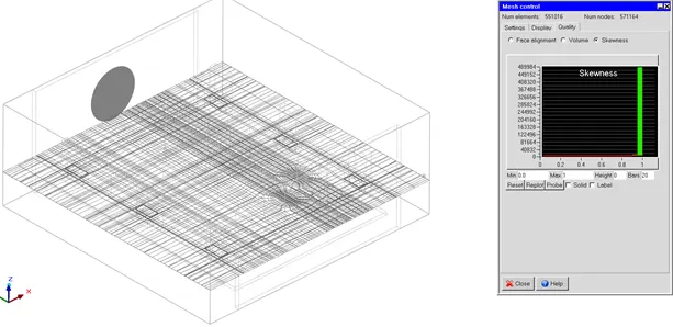
The processing process considers 10 second as a transient simulation, applying a velocity of 0.1m/s in the fan, with heat sources in the capacitors and transformer subassembly, having as outlets the wall facing the fan, out the grill section.
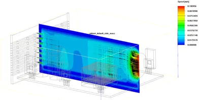
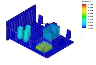
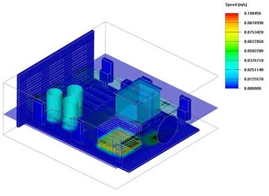
The postprocessing has its following contours, and vectors images, having the temperature, velocity and speed of the planes and surfaces of the elements within the assembly.
Speed contour in plane with vectors of direction.
Surface contour of temperature seeing the heat generation increasing and dissipating.
Surface temperature contour with vectors and contour of speed direction in plane.
Conclusion
A forced convection analysis in ICEPAK was performed, adding personal not standard or selected valued of power generation and fan velocity and obtaining a postprocessing of the results obtained.