Week 5.3 - Forced convection Analysis
Theory:
Forced convection is a mechanism or type of transport, in which fluid motion is generated by an external source (like a pump, fan, suction device, etc.). Alongside natural convection, thermal radiation , and thermal conduction it is one of the methods of heat transfer and allows significant amounts of heat energy to be transported very efficiently.
Natural convection can create a noticeable difference in temperature within a home. Often this becomes places where certain parts of the house are warmer and certain parts are cooler. Forced convection creates a more uniform and therefore comfortable temperature throughout the entire home. This reduces cold spots in the house, reducing the need to crank the thermostat to a higher temperature, or putting on sweaters.
Total no of bodies in the CAD model is calculated into icepack primitive objects in space claim and modify the components in icepack modules and define the correct physics.
Total no of bodies in the CAD model is calculated. The depending on the functionalities of the individual bodies or group of bodies are segregated.
Types of bodies.
Focus bodies: the body which emits some heat or obstructs the flow of system.
Necessary bodies: the bodies which will have effect on the focus bodies.
Peripheral bodies: the bodies may or may not have effect on the focus bodies.
Dispensable bodies: the small bodies which have no effect on the physics of system.
Geometry cleaning:
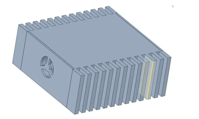
the geometry of enclosure
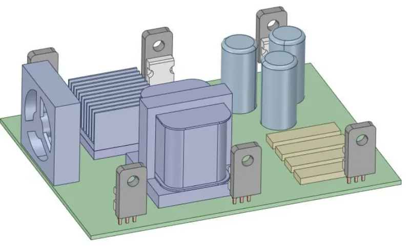
Inner componenets
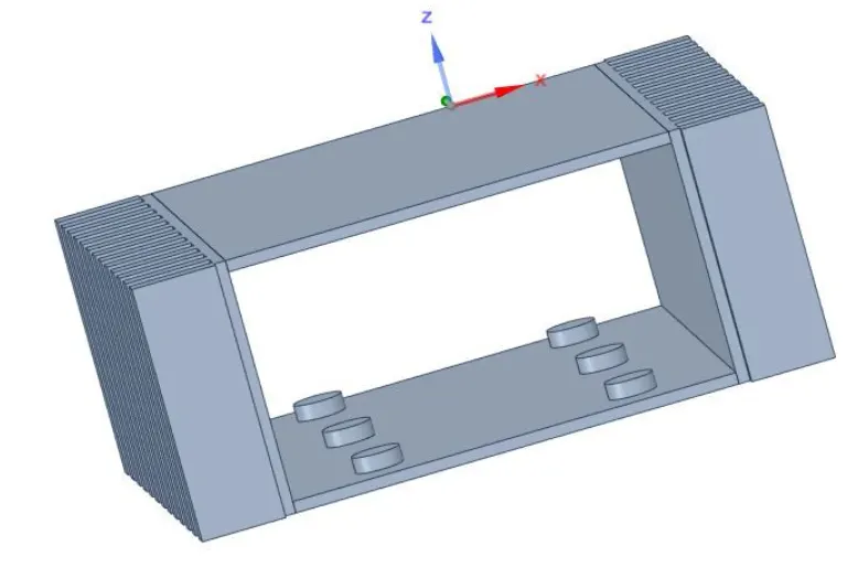
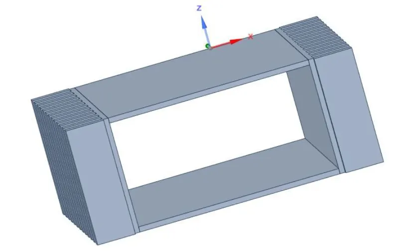
Remove unnecessary part from the enclosure by using split command.
Before split
After split
Delete curvature part from the transformer set
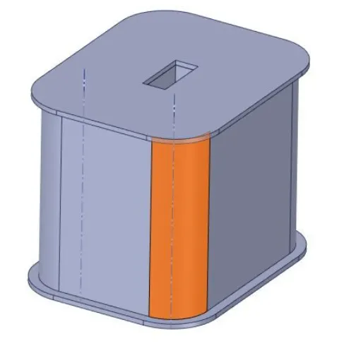
Fill gaps within the surrounding surfaces or solid.
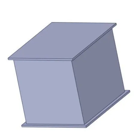
Simplify the cad objects in icepack objects.
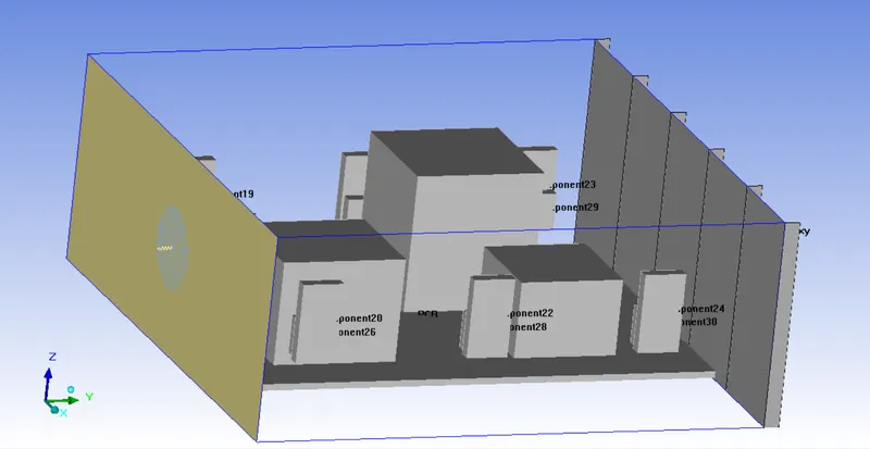
Grille and fan are modelled in icepack
The complete geometrical conversion.
Meshing setup:
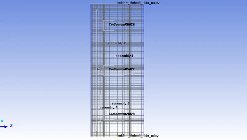
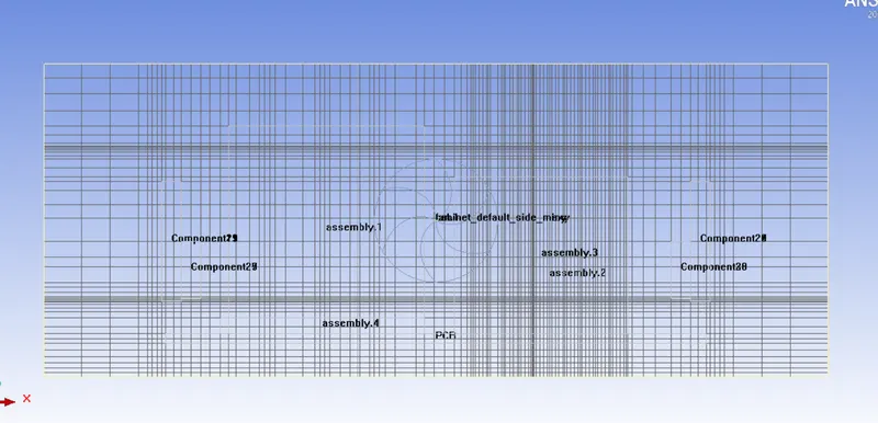
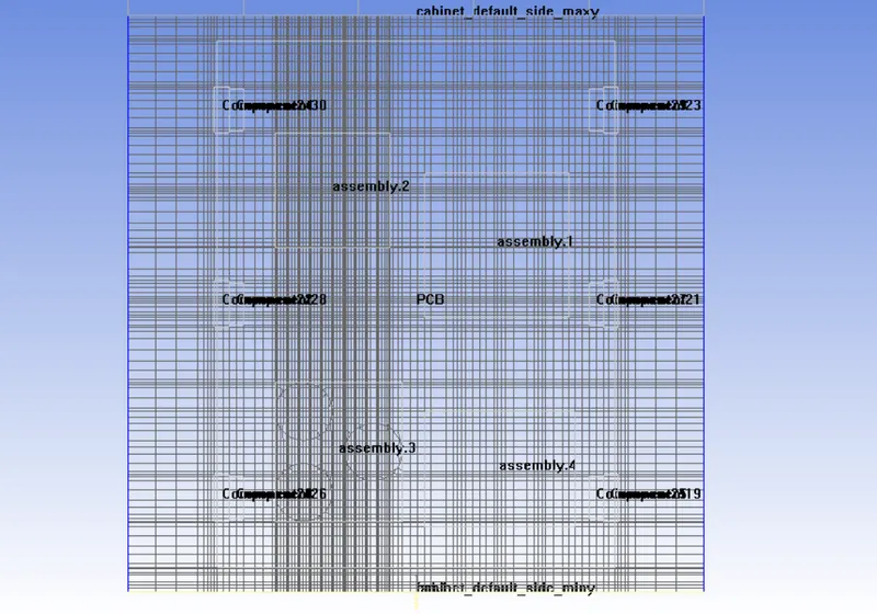
The enclosure is divided in several assemblies.
4 mesh assemblies are being constructed.
Checking mesh
Macros > productivity > validation > automatic case check tool
Global mesh settings
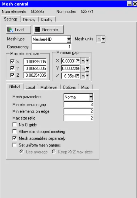
Mesh x:
Mesh Y;
Mesh z:
Physics setup:
The transformer coil setup and the heat sink along with BGA package are the two heat generating sources in the model and heat generated value is provided as input.
Total power generated is 2W for both the components.
Solver: 3D navier stokes solver is used to study the computational domain.
General set up:
Variables solved: flow and thermal
Radiation: off
Transient setup: steady
No of iterations: 1000
Parallel setup: 2 processors
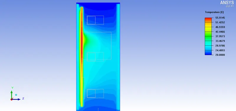
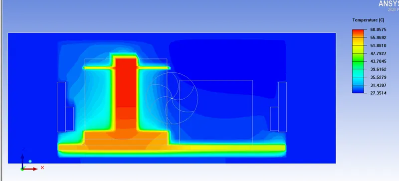
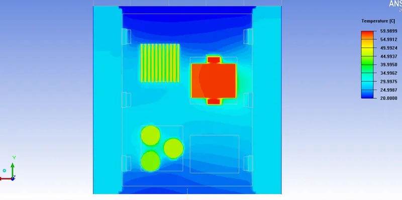
Post processing plots
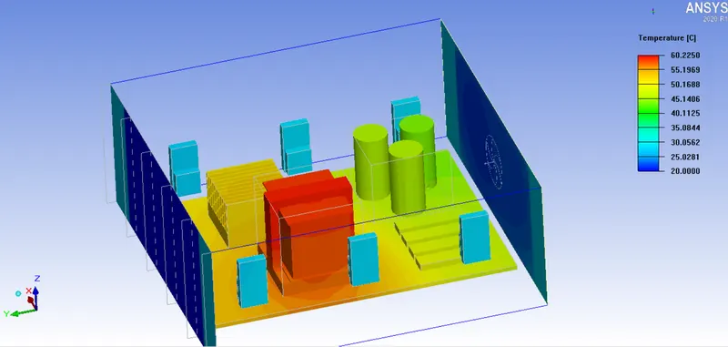
Temperature contour
Temperature in X axis
Temperature in Y axis
Temperature in Z axis
Conclusion:
- The geometric cleaning is performed to capture the thermal cooling effect significantly.
- The assembly meshing is performed to reduce the mesh bleeding effect and mesh counts.
- The temperature contour shows appropriate results for cooling the internal components of the enclosure.