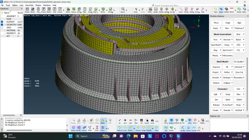
Week - 5 - 2D meshing for Plastic components
Title: Plastic Bottle Cap Model - Quality Control and Mesh Generation
OBJECTIVE : The objective of this project is to perform quality control checks on the given CAD design model of a plastic bottle cap and correct any geometrical errors. The scope of the project includes generating mid-surfaces of all the parts provided, creating PID and assigning thickness to all mid-surfaces, and generating a well-meshed model with the given quality criteria. The project involves adhering to specific quality parameters listed in the table below, which include target/average length, minimum and maximum length, aspect ratio, warpage, skewness, Jacobian, minimum and maximum quadrilateral angles, and minimum and maximum triangular angles. The desired percentage of triangles is also specified.
Quality Criteria: The following quality criteria were provided for the mesh generation of the plastic bottle cap model:
S.No Quality Criteria Value
1 Target/Average length 1
2 Minimum Length 0.5
3 Maximum Length 3
4 Aspect 3
5 Warpage 15
6 Skewness 45
7 Jacobian 0.7
8 Minimum Quad Angle 45
9 Maximum Quad Angle 135
10 Minimum Tria Angle 30
11 Maximum Tria Angle 120
12 Tria Percentage 15
PROCEDURE – The first step is to import the given CAD design model into the pre-processing unit tool in Ansa.
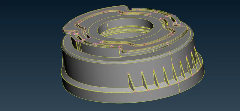
Upon importing the CAD design, it was observed that there were several geometrical errors present in the model such as numerous hot points located in unwanted areas, and multiple double and triple cones present where they were not required. Additionally, there were some unwanted features, general lines, present in the model that needed to be corrected, and all errors needed to be eliminated.
To address these issues, the topology clean-up feature was used, which can be found under the "faces" option. After selecting the entire module by slide, the "topo" option was performed through a right-click, and all modules were selected by performing a mouse middle-click.
To ensure uniformity in the model, every surface needs to be oriented in a particular direction through the orient function. Additionally, there are several hot points present in close proximity to each other and in an unarranged manner. To address this issue, the resolution needs to be arranged first, followed by the resolution of constraints using the length option. The value of perimeter and macros 1 needs to be put down and applied simultaneously, one by one.
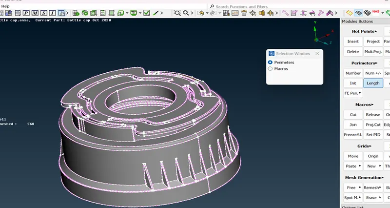
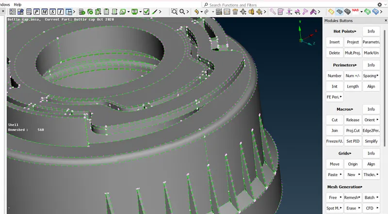
Next, the geometrical errors in the model need to be corrected. This can be done by using the geometry checking tool and fixing the errors one by one. It is important to execute each correction and verify that it has been successfully fixed.
After correcting the geometrical errors, the mid-surface of all parts needs to be generated. This can be done by selecting the part and using the "Create Mid Surface" tool in the pre-processing unit. Once the mid-surfaces are generated, the PID and thickness assignment needs to be enabled for all mid-surfaces.
To ensure good mesh flow and meet the given quality criteria, the mesh needs to be generated with a low concentration of triangles and proper mesh flow. The quality criteria includes target/average length, minimum and maximum length, aspect, warpage, skewness, jacobian, minimum and maximum quad angle, and minimum and maximum tria angle, as well as the percentage of triangles.
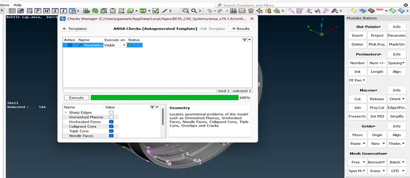
In order to extract the mid surface and assign PID to each component, I started with the top of the model and measured the thickness of the component. As the plastic component thickness varies in different parts, I carefully measured the thickness in two to three positions and confirmed the values. Next, I used the weld point option to weld the hot points in both directions and projected it. After measuring the thickness again, I divided the thickness value in half and selected the entity. Then, I offset it by putting negative values.
I repeated this process for all the components present in the model and ensured that the mid surface was extracted correctly with the correct thickness assigned to each part. Finally, I checked the mesh quality criteria such as target/average length, minimum and maximum length, aspect ratio, warpage, skewness, jacobian, minimum and maximum quad angle, minimum and maximum triangle angle, and triangle percentage. I adjusted the mesh flow to ensure that all the given quality parameters were met.
After completing all these steps, I was able to generate a final model with a properly extracted mid surface, assigned PID, and high-quality mesh flow that met all the given quality criteria
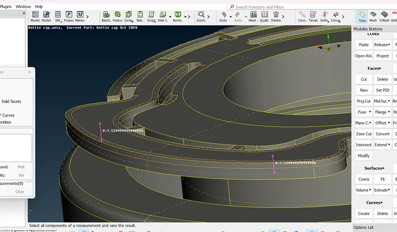
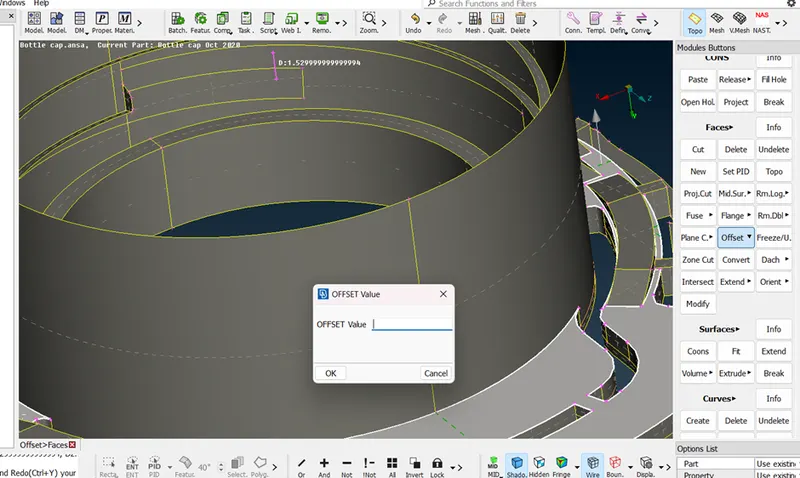
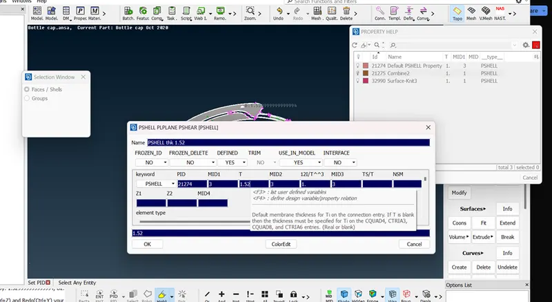
Once all mid surfaces have been created and assigned PIDs, the next step is to clean up the geometry and ensure proper mesh flow. To achieve this, the given quality criteria for the model are taken into consideration, including target/average length, minimum and maximum length, aspect, warpage, skewness, Jacobian, minimum quad angle, maximum quad angle, minimum tria angle, maximum tria angle, and tria percentage.
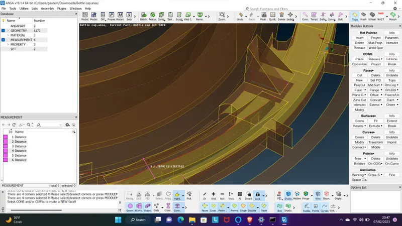
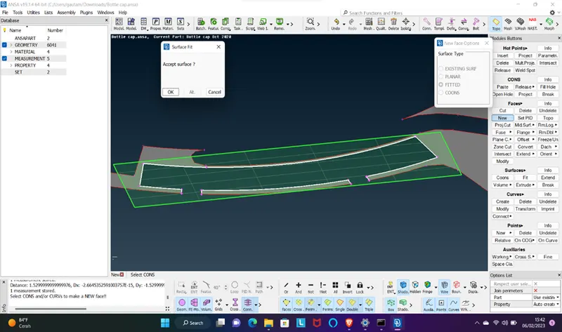
But some complicated area creating mid surface is tough like threads and round ribs parts
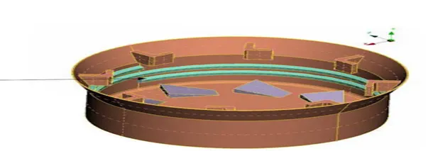
Middle option presented in under curves option used and selected two cons and created curves of the middle of the cons.
By doing this curves are come in top surface of threads after that the middle curves creating the base mid surface
Pick double creating curves and creating a new face that is mid surface of that threads.
But there some triple cons are create that three face connected
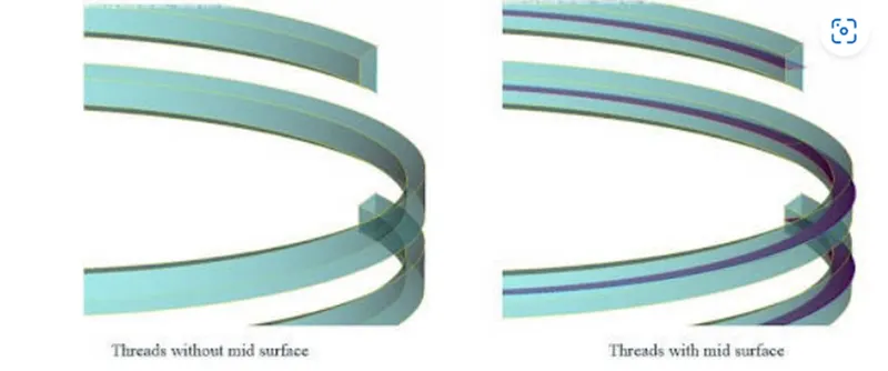
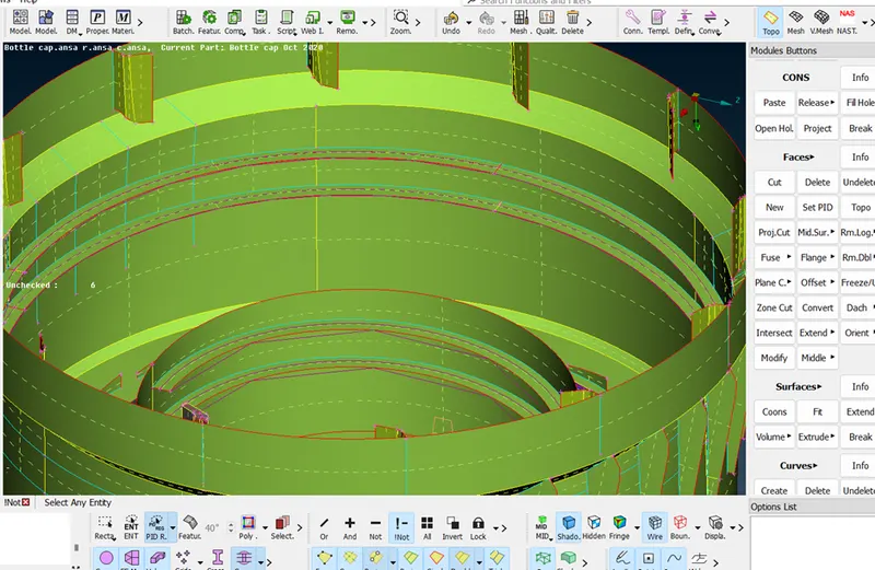
After creating mid surfaces for all the components and setting PID values, the next step is to assign thickness to the mid surfaces. For this, the thickness value of each component is measured and assigned accordingly. The thickness assignment is done using the thickness option under the assign menu.
However, assigning thickness to the mid surface of complicated components such as the inner teeth can be time-consuming. To save time, the transform option is used to create mid surfaces for all the teeth by rotating the mid surface of one tooth. The thickness of each tooth is then measured and assigned by offsetting the mid surface by half of the measured thickness value.
Once the thickness is assigned to all the mid surfaces, the next step is to ensure proper mesh flow. The quality criteria mentioned in the given table are taken into consideration to achieve a mesh with low tria concentration and proper mesh flow. The meshing is done using the mesh option under the pre-processing unit tool in Ansa.
After meshing, the model is checked for any geometrical errors using the geometry check option. Any errors found are corrected manually. Finally, the model is analyzed and verified for quality parameters such as aspect ratio, warpage, skewness, Jacobian, quad angle, and tria angle. Any discrepancies are corrected until all the quality parameters meet the given values.
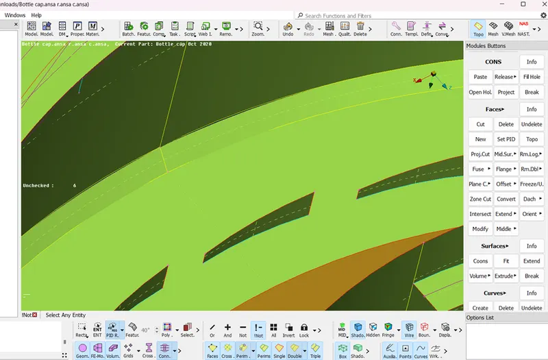
To enable the rotation and duplication of the mid surface of the teeth, it was necessary to extend and join the surfaces of the parts. However, in order to perform this operation successfully, a center point was required. To obtain this center point, the on COG option was used in the points section, selecting two circular lines one by one. Once the center point was created, the mid surface of the first tooth was duplicated using the rotate option, which required the axis of rotation to be specified.
To create the axis of rotation for the teeth, the total angle of the circle was divided by the total number of teeth. Once the axis of rotation was set, it was observed that the remaining teeth's mid surfaces could be created by duplicating the first mid surface and rotating it according to the specified axis. As a result, all the mid surfaces for the teeth were created quickly and efficiently.
Angle between two entities = Total angle of a circle / Total no. of teeth.
After that we observes that the Remaining teeth mid surface will be creating duplicating successfully
Learning Outcomes:
Through this challenge, I have gained knowledge and skills related to creating mid surfaces in complicated areas of CAD designs. I have learned how to use transform and rotate options to duplicate mid surfaces of teeth and other components, and how to create a center point for the axis of rotation using the COG option.
Additionally, I have learned how to identify and avoid double and triple cons, and how to perform topology clean-up and geometry checks to correct geometrical errors in the CAD model. I have also gained experience in setting PID values and creating PIDs for different components of the design.
CONCLUSION - Overall, this challenge has improved my proficiency in CAD software tools and techniques, and has enhanced my ability to efficiently and accurately perform tasks related to mid surface extraction, geometry correction, and component identification and labeling
The process of creating mid surfaces in complicated areas has been learned, and the use of the transform and rotation options to duplicate entities according to the requirements of the model has been mastered. The identification and avoidance of double and triple cons have been practiced. Overall, the challenge has been a great learning experience and has improved the skills and knowledge related to pre-processing in Ansa.
RESULT - I successfully generated mid-surfaces and cleaned up the given component's geometry. I also meshed the component with low triangle concentration, ensuring proper mesh flow. Furthermore, I ensured that the mesh passed all the given quality parameters.