Week 4 - 2D Meshing for Sheet Metal
CCB Model SHEET METAL
Introduction: The objective of this report is to document the process of creating a CCB sheet metal model, including the correction of geometrical errors clean up of given component, extraction of mid surfaces, generating mesh with low trias concentration and proper mesh flow and thickness assignment. The goal of the model is to achieve good mesh flow with the given element and meet the quality criteria specified and qualify all given quality parameter.
|
S.No |
Quality Criteria |
Value |
|
1 |
Target/Average length |
5 |
|
2 |
Minimum Length |
3 |
|
3 |
Maximum Length |
7 |
|
4 |
Aspect |
3 |
|
5 |
Warpage |
15 |
|
6 |
Skewness |
45 |
|
7 |
Jacobian |
0.7 |
|
8 |
Minimum Quad Angle |
45 |
|
9 |
Maximum Quad Angle |
135 |
|
10 |
Minimum Tria Angle |
30 |
|
11 |
Maximum Tria Angle |
120 |
|
10 |
Tria Percentage |
15 |
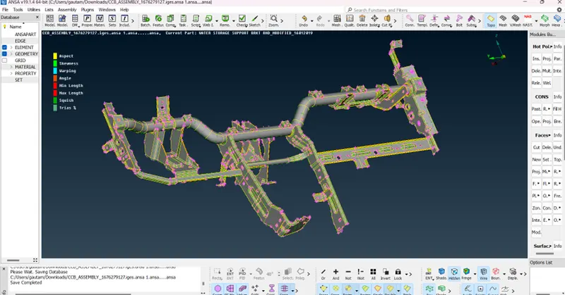
Procedure: The first step in the process was to import the given cad design model into the pre-processing unit tool in Ansa. The model had several geometrical errors that needed to be corrected. This involved removing unwanted features such as general lines, double and triple cons, and hot points that were present in unwanted places. Topology cleanup was performed using the module buttons under faces option. The topo option was done through right-click and selecting the entire module by slide, and then mouse middle-click was used for performing the action. The surface was then oriented in one particular direction to eliminate hot points that were near each other and unarranged to arranged.
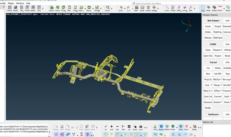
Next, geometrical errors correction was performed, and all errors were fixed one by one. This was followed by the extraction of mid surfaces for each component part, and a PID was assigned to each mid surface. The thickness of each component was measured, but in sheet metal component the thickness were not varrying its same and the mid surface was extracted accordingly with right option .
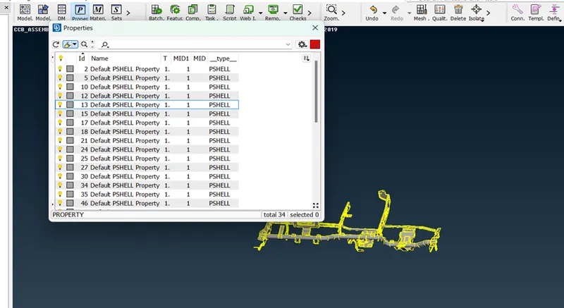
I fix errors that appear such as extra lines through the fix option geometry checks , needle face errors, or triple cons and do manually using the cut and join options in the Topo module Using the measurement option, i measure the component thickness to check if it is equal everywhere or if it varies, which will affect the creation of the mid-surface.
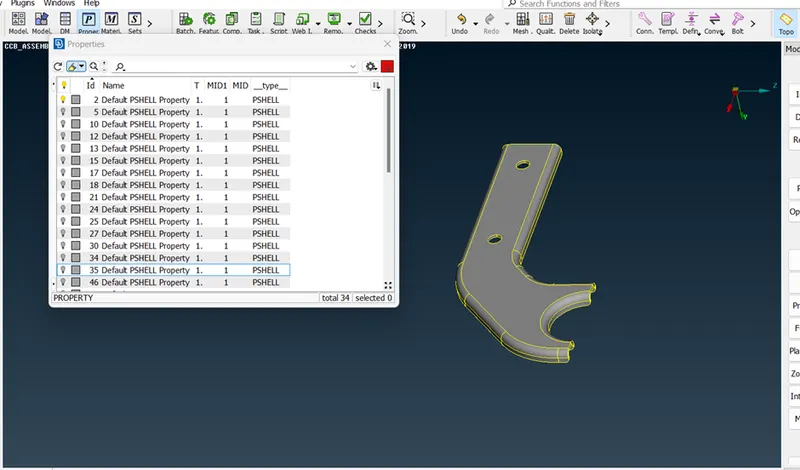
If the thickness is the same everywhere, I create the mid-surface and mesh it easily.
I choose the mid-surface option or skin option to create the mid-surface because component's thickness is equal everywhere and it creates automatically and accurately in less time.
I check for any double lines or hot points near each other and fix it using the cut and join option present in the topo module avoid sharp edges or corners for better mesh flow and fix them.
After doing all that things then I do mesh and good geometrical
Before that provide a target element size, mesh parameter, and quality criteria for the components.
I go for mesh option for meshing the mid surface component after providing all the necessary details and try to achieve a better mesh flow and smoothness.
I check the mesh quality to ensure that it meets the desired criteria and make any necessary adjustments
During the meshing process, some errors and off elements occur, such as maximum or minimum element length triangles touching each other. To resolve this issue Adjust the mesh density or refine it in areas where errors or off elements are present.
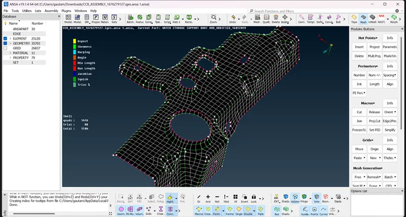
for resolves this all errors I can use smooth or reconstruct option for trias i use split and paste option to move the trias backward forward swap it and correct it…
some were specially in corner edge area the elements get fails and create disturbance elements where I do some smooth option after that moving trias and quad elements in right place or use cut option to create cut line and manage it.
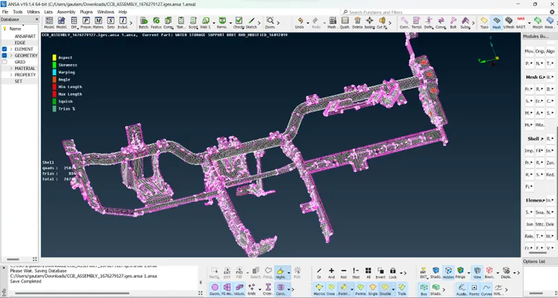
So many trais are present then I take one by one trais and make it in proper way according to requrements given I do split option for two opposite trais and make it correct and same direction trias I just swap it.
For somewhere max/min elements length are not going through the smooth and trais moving option then I do transform option and move the trias node in given parameter and correct it
In component there are many general lines and extra hot points are present there are no need of it I need to take care of it by the help of module options somewhere is using cut and somewhere join option are use it and extra hot points need to delete it.
All the Same things I do part by part of the all components and many more things I do that present it and I am trying to do give best result on it
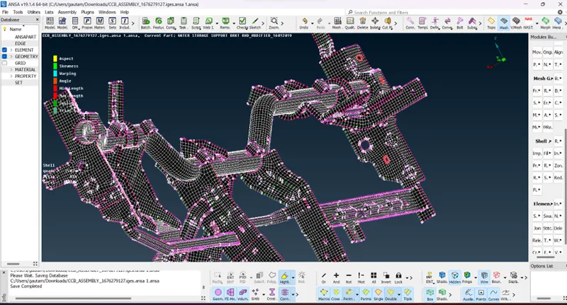
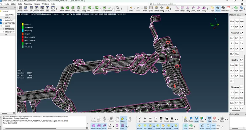
Learning Outcomes:
- Understanding the importance of topology Cleanup and surface smoothing in creating a high-quality mesh model.
- Knowledge of techniques for eliminating rotating quads and opposite triangles, and for eliminating triangles near free edges, holes, or fillets.
- Understanding the importance of applying quality criteria to ensure zero OFF elements.
- Knowledge of how to enable thickness and draw the shell as solid
- In this challenge I learns many things just like how to creating mid surface in complicated area and also I learn t according to requriment of entity and where the double triple cons are require and the avoided that things.
- RESULT – Doing geometrical cleanup of all parts Generating midsurface and generating geometry cleanup of the given component and mesh of the given component with low tria concentration and proper mesh flow I also do pass all the given quality parameter with better mesh flow
- FINAL MODEL Images