Week - 5 - 2D meshing for Plastic components
Report
Aim
- To check for the geometrical errors and take the mid surface by suitable mid surfacing techniques.
- To assign PID and Thickness for all the mid surfaces.
- To mesh the same with the given element Quality criteria.
Theory
Plastic components
Components with irregular thickness and different places are considered as Plastic components. Unlike Sheet metal components these can’t be extracted mid-surface using FACES – MIDDLE SURFACE– Skin
Procedure
The component is subjected to various operations to deliver a better mesh at the end. There are few steps followed to deliver the proper mesh, they are:
- Geometry clean-up,
- Extracting the middle surface,
- Meshing,
- Quality checking,
- Assigning thickness.
- Import component and Go for Length option from the mesh module to find out the actual geometry of a model.
- Perform topo on it, as the model is too distorted after importing from different software.
- After understanding the geometry, we can go for mid surfacing,
- After mid-surfacing 2D meshing is done by setting the Quality criteria.
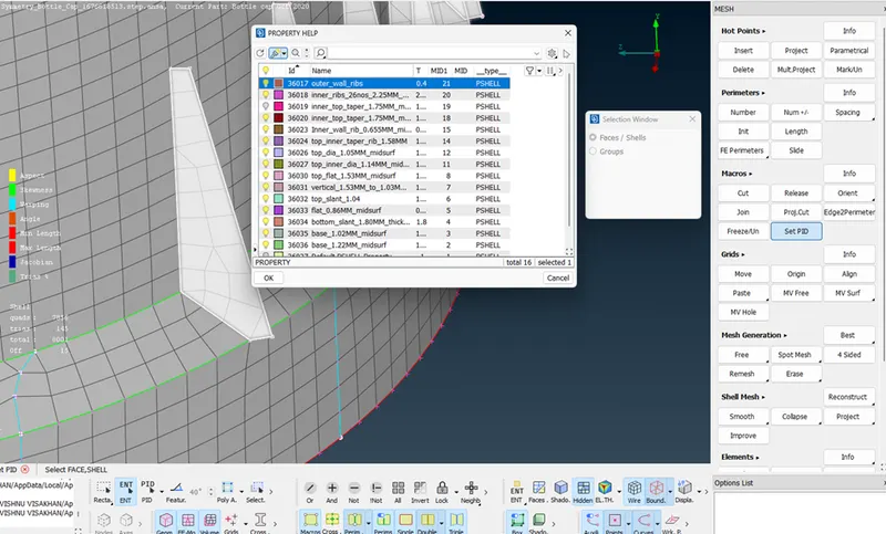
- Assign property to each section using set PID option.
- Solved the Quality issues generated during meshing and move forward.
- After completing the meshing as per quality criteria, assign the thickness.
- The week 5 challenge model bottle cap was loaded on the ANSA workbench, the model looked as follows:
Geometry Check and clean:
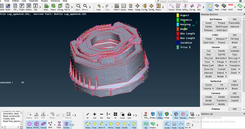
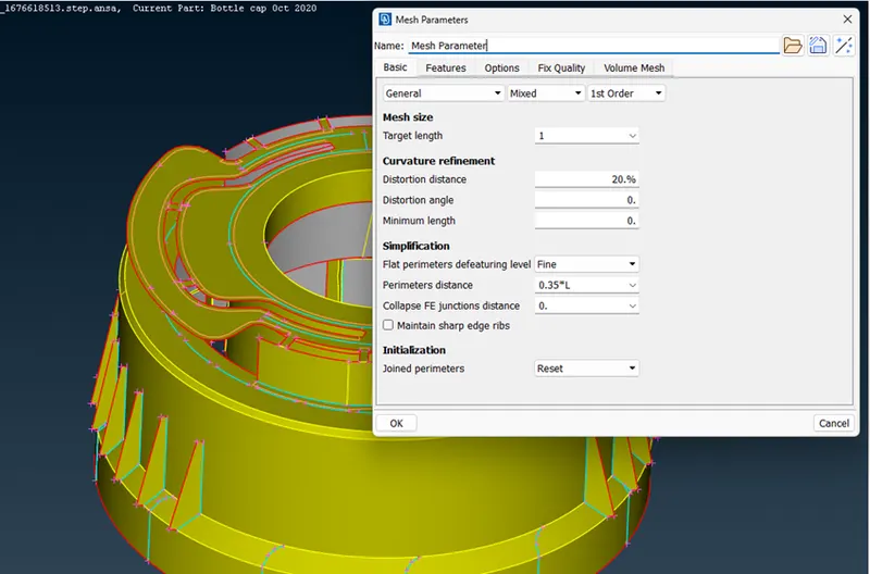
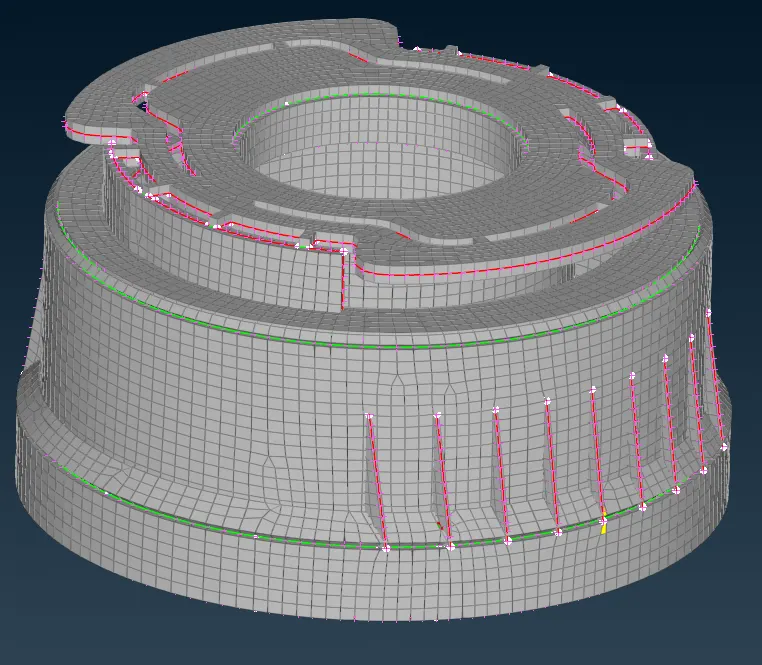
It is seen the model features are not clearly visible, many red lines are visible meaning single cons. Topo must be done to the geometry and in mesh module, the length of macros is set at 1 to get the real shape of features as follows:
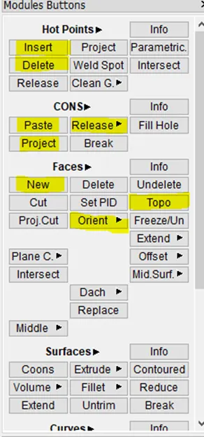
After checking the model, the clean-up tools like
- topo,
- delete points,
- new face, are used.
The highlighted options are used randomly in the model.
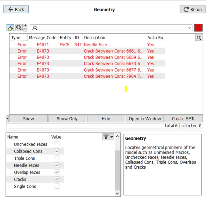
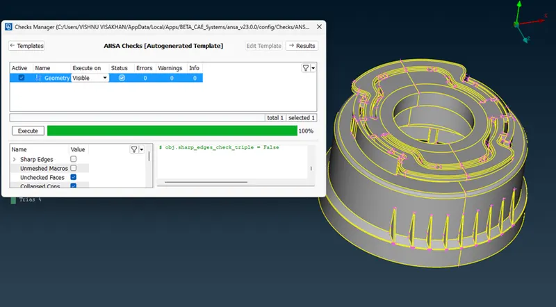
The model was later checked for geometrical errors using Checks for Geometry and errors like crack, unchecked faces, needle faces were fixed.
Mid Surfacing
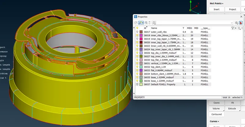
Once the model is error-free, the extraction of the mid surface was done. Since its a plastic model and had different thicknesses for each feature, the mid surface was extracted manually.
Since thickness differed in each feature, after extracting mid surface individually for each feature PID was assigned with respective thickness for the feature.
Mid surfacing of teeth
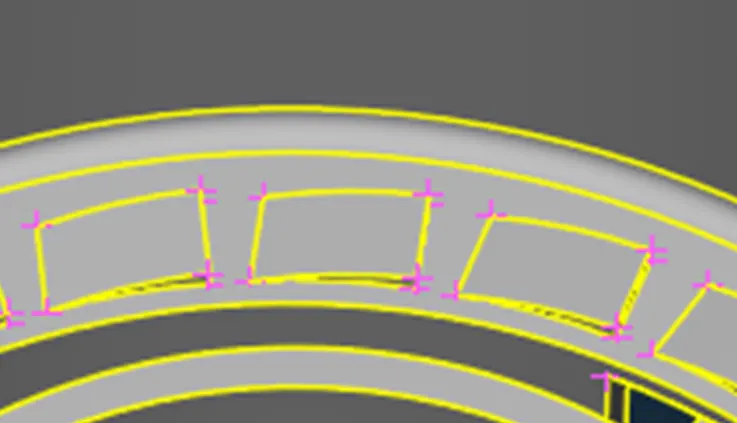
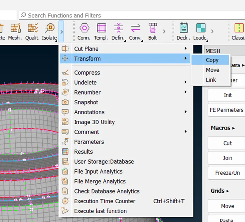
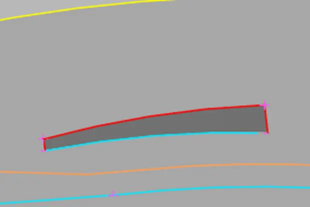
This kind of features cannot be captured using 'offset or the 'middle' options. So manually a mid-surface was created using curves middle, new face options. The curve was created at the thicker side of the teeth. Using that curve and the side touching the bottom surface a new surface was created and PID was set with average thickness. This was done for one tooth and later translated to all the teeth using transform rotate.
Select the entity
Create COG
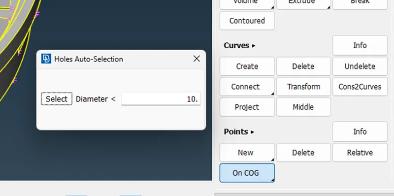
Select the defined COG
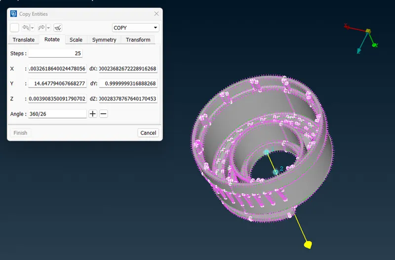
Mid surfacing of ribs and other features using FACES – MIDDLE - SINGLE
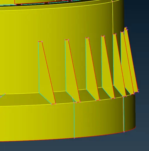
Mid surfacing of ribs and other features using FACES – MIDDLE - MULTI
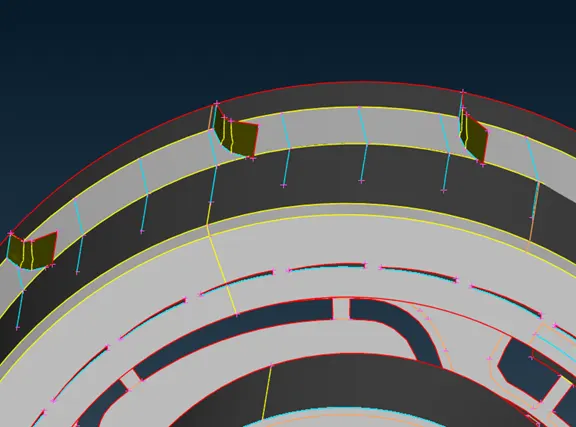
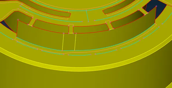
Once the mid surface was extracted, the mid surface was run for geometry checks before starting with mesh.
Meshing
- The quality criteria given in the challenge was setup before starting with mesh.
- The meshing was done using, Classic Mesh - Mesh generation - Best
- The mesh generated was reconstructed using Reconstruct option.
- To achieve the good mesh flow without quality compromise, mesh was altered using split, swap, MV surf, smooth options.
- The construction lines which would not affect geometry were removed to have better mesh flow.
Some quality issues are as follows:
- At the junction of rib and the wall, it is observed that the top end of the rib and the wall are in 2 different vertical planes and the hot point at the junction of both surfaces is below the wall's end. This is leading to quality issues as shown below. The issue was addressed by chopping off the area above the junction without affecting the geometry.
Quality Checking
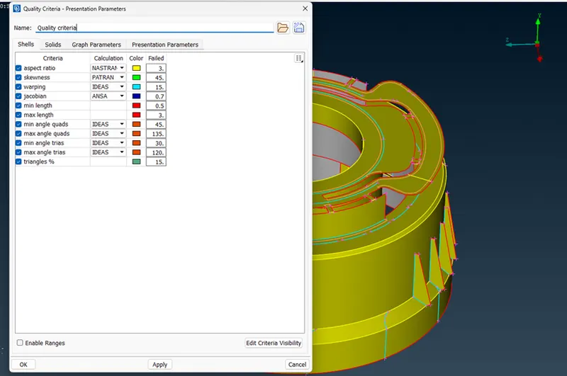
The given quality parameter has been updated.
Assigning Thickness
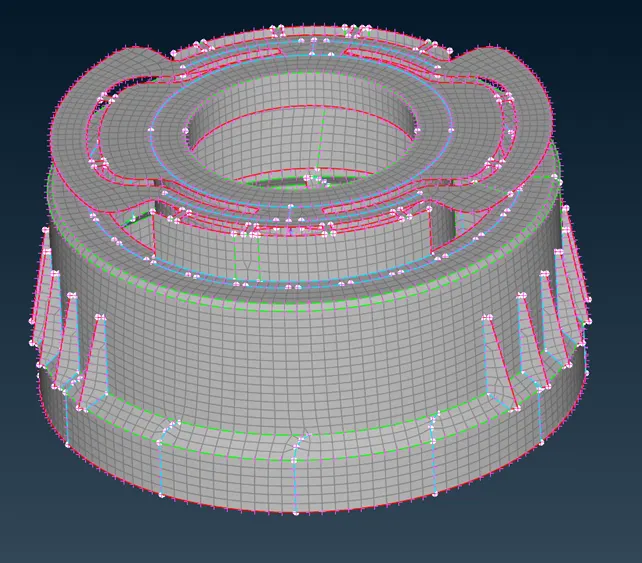
Final Mesh Medel
Conclusion:
- The given component is manually taken a mid-surface and then the middle surface is meshed using the given quality parameters.
- The mesh is edited with the useful mesh edit tools and the thickness is assigned to the component.
- Some of the elements are failing in aspect ratio and minimum angle condition in places of multiple closed feature line (triple cons).
References:
FAQ-3 - https://skill-lync.com/knowledgebase/fan-housing-faq-3
FAQ-1 - https://skill-lync.com/knowledgebase/faq-fan-housing-practice-model-week-4
FAQ-2 - https://skill-lync.com/knowledgebase/fan-housing-model-faq
Thank you for the mentoring and clearing my doubts.