Week 5.2 - Multi Level Meshing
Aim:-
The objective of the project is to create the multi level meshing to resolve CAD objects in the Icepak model and reduce the original mesh elements.
Objective:-
- Create non-conformal mesh assembly and use mesh separately option with slack values.
- Use set uniform parameters and use average on 1 assembly, in multi-level meshing tab allow multi-level meshing up to level 2 for the objects.
- Generate mesh & observe in mesh reduction.
- Do visual inspection & check for quality.
Model:-
File --> unpack project --> hanging node.tzr - This opens the hanging node model and click on View --> default shading --> solid.
Geometry:-
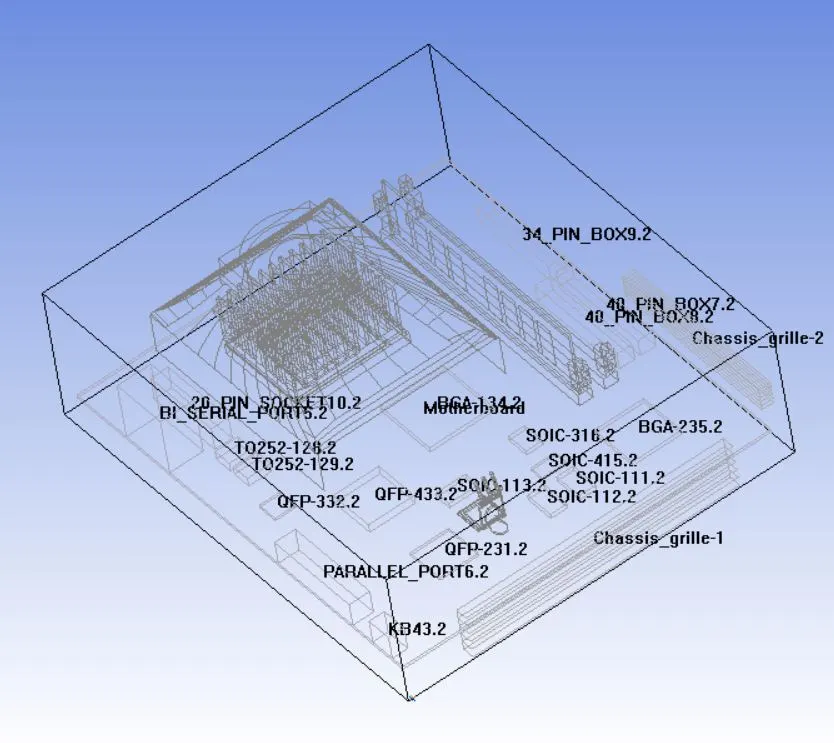
- The below picture the given CAD Model to generate the mesh using the multi-level parameters.
- The Geometry contains Fan, Capacitors, solid blocks, heat sink, and printed circuit boards, etc.
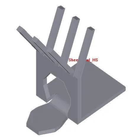
The given Icepak model contains the following two CAD objects:
i. SheetMetal_HS
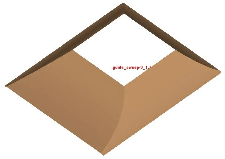
ii. guide_sweep-0_1.1
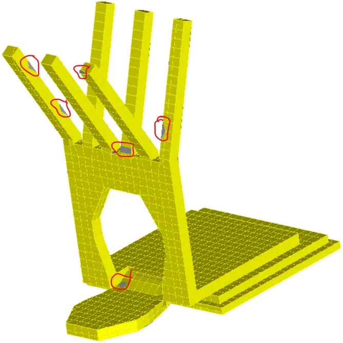
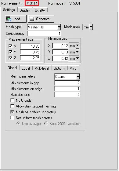
In order to resolve these CAD objects and avoid mesh bleeding the model employs local mesh refinement with non-conformal meshing. Additionally the model also defines per-object meshing parameters for certain objects in order to refine the mesh near them. If the model is meshed without any modifications, 713114 (nearly 700000) elements are generated which is a lot. Furthermore even with this level of mesh refinement the CAD objects are not resolved effectively as shown in the images attached below.
SheetMetal_HS
guide_sweep-0_1.1
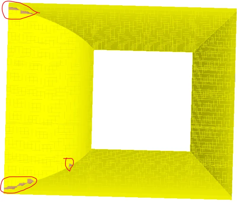
In the current project, multi-level meshing is applied to resolve the CAD objects effectively with a coarse background mesh. Multi-level meshing enables local refinement starting from a Cartesian mesh generated using the maximum element sizes specified by the user. The refinement can be controlled such that the initial Cartesian mesh is refined in an area where the mesh needs to be finer in order to resolve some geometrical features or gaps. This significantly reduces the overall mesh count while providing adequate mesh resolution where it is needed. The image attached below shows an application of multi-level meshing.
Meshing
As mentioned earlier, if the given model is meshed without any modifications 713114 elements are generated. The image attached below shows the Mesh control window.
The following steps are used to better resolve the CAD objects, and reduce the initial mesh count
1. Non-conformal meshing allows the user to refine the mesh selectively within the sub-region around an assembly where it is needed, and use a coarse mesh in the rest of the model. The model already contains multiple assemblies that employ non-conformal meshing.
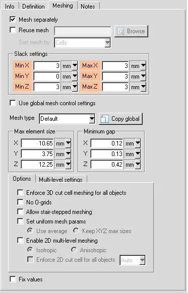
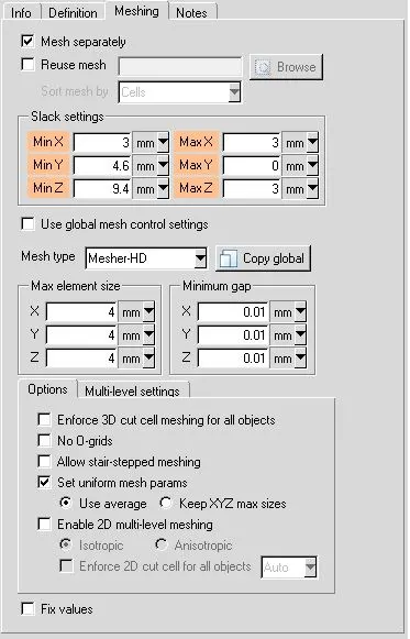
2. The Mesh separately option available in the Meshing tab of individual assembly settings allows the user to mesh the sub-region around the assembly independently of the mesh outside it. By default the bounding box of the assembly has the exact size necessary to enclose the objects constituting the assembly. Defining a slack region allows the user to make the bounding box slightly larger. The Mesh separately option is enabled for the assembly DIMMs.1 in the model and appropriate slack values are specified. The image attached below shows the assembly settings applied for DIMMs.1.
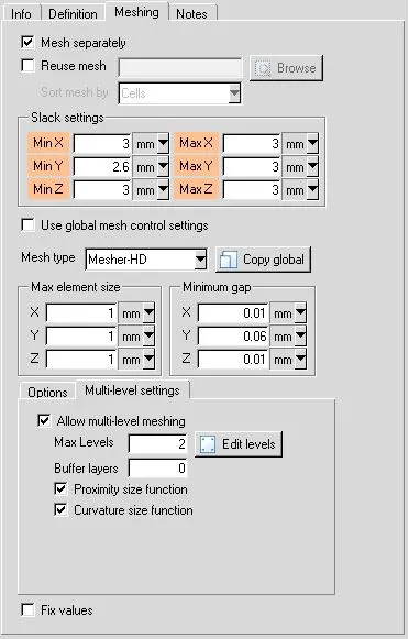
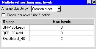
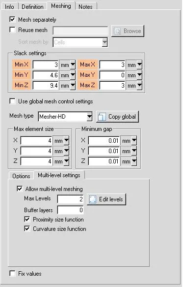
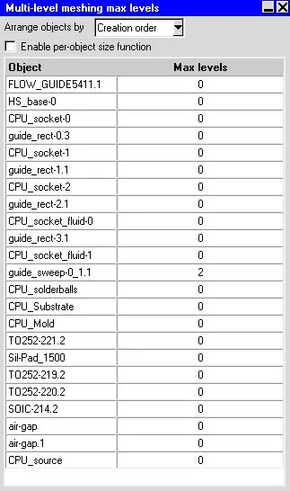
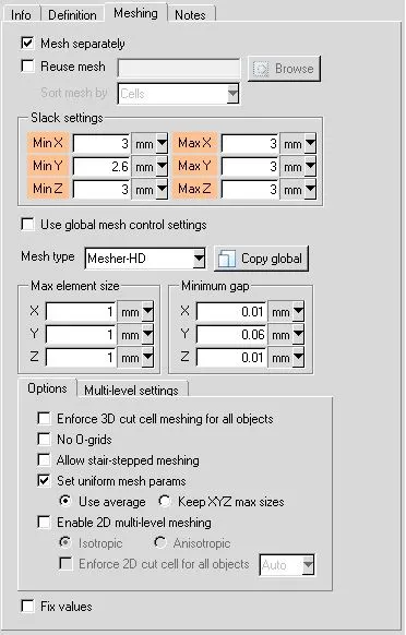
3.Multi-level meshing allows the user to locally refine the mesh in the areas where the mesh needs to be finer in order to resolve some geometrical features or gaps, while keeping a coarse Cartesian mesh in the rest of the model. The local mesh refinement can be controlled using Max levels which indicate the maximum number of levels that may be required to achieve the desired mesh refinement based on curvature/proximity. In the given model, multi-level meshing is allowed for the assemblies sheetmetal_hs_assy.1 and fan_guide.1 up to level 2 for the objects. In the Multi-level meshing max levels window Max levels is set to 2 for the objects SheetMetal_HS and guide_sweep-0_1.1, present in the assemblies sheetmetal_hs_assy.1 and fan_guide.1 respectively. Since multi-level meshing is being used the maximum element sizes can be increased for the two assemblies, without compromising the mesh resolution of objects within them. For the assembly sheetmetal_hs_assy.1, maximum element sizes along X, Y and Z coordinates are set to 1 mm each; minimum gaps along the X and Z coordinates are set to 0.01 mm each. For the assembly fan_guide.1, the maximum element sizes along the X, Y and Z coordinates are set to 4 mm each. The images attached below show the multi-level settings applied for the assemblies sheetmetal_hs_assy.1 and fan_guide.1.
sheetmetal_hs_assy.1
fan_guide.1
Set uniform mesh params with the option Use average allows the user to create a uniform mesh with the same mesh size in all coordinate directions. The mesh size is calculated by averaging the specified maximum element sizes. Set uniform mesh params with the option Use average is enabled for the assemblies sheetmetal_hs_assy.1 and fan_guide.1 as shown in the images attached below.
sheetmetal_hs_assy.1
fan_guide.1
After completing the above steps, the computational mesh is generated. The image attached below shows the Mesh control window.
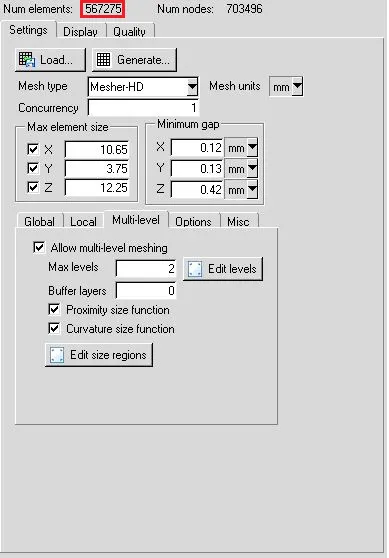
The image highlights that the number of elements generated in the mesh is 567275 (nearly 500000). Hence we see a significant reduction in the overall mesh count.
Visual inspection
Once the mesh has been created it must be inspected visually to ensure that it is able to resolve the design objects in the model effectively.
1. Surface mesh on the CAD object SheetMetal_HS
The image attached below shows the mesh plotted on the surface of the CAD object SheetMetal_HS.
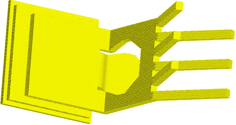
The mesh appears to resolve the CAD object much better.
2. Surface mesh on the CAD object guide_sweep-0.1.1
The image attached below shows the mesh plotted on the surface of the CAD object guide_sweep-0_1.1.
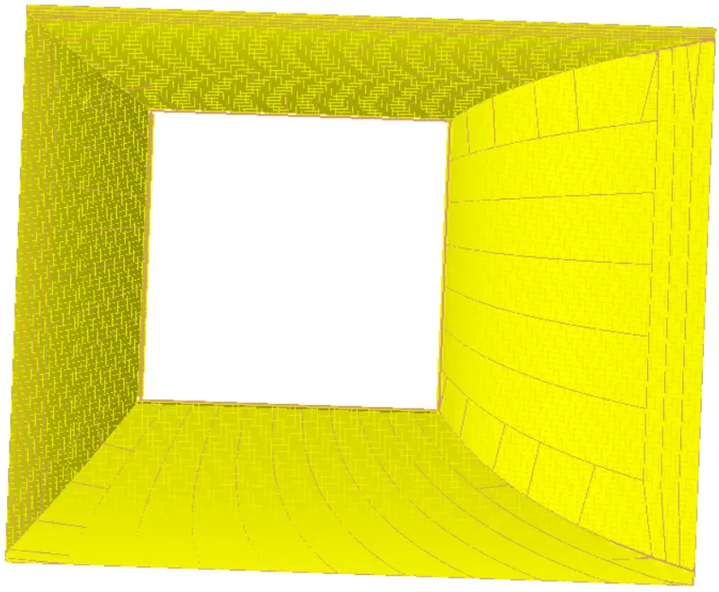
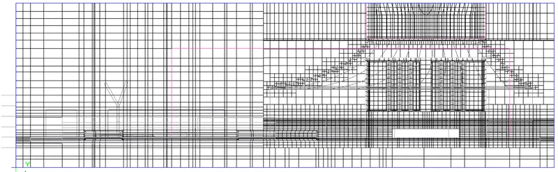
X plane through the center
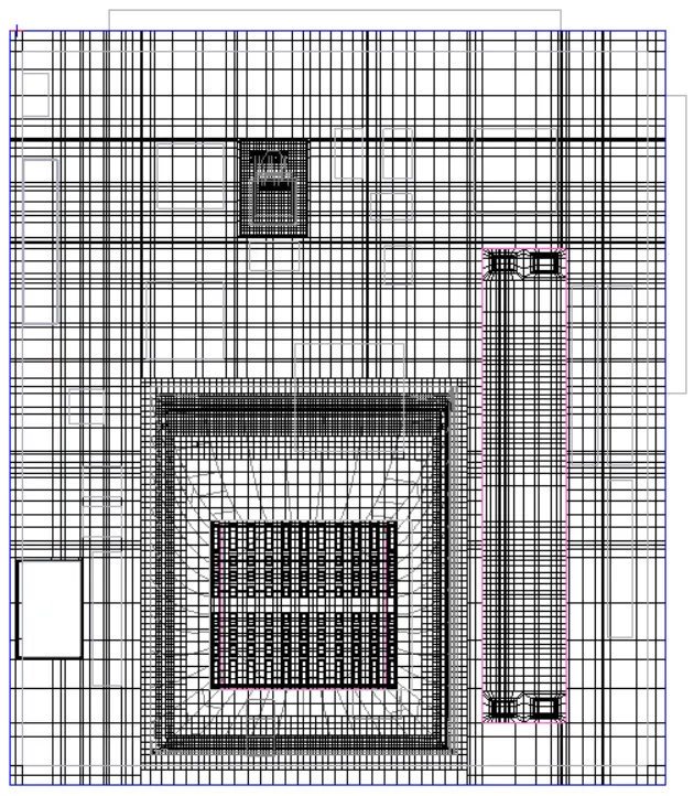
The image attached below shows the mesh plotted on the cut-plane passing through the center of the cabinet and perpendicular to the X axis.
Y plane through the center
Z plane through the center
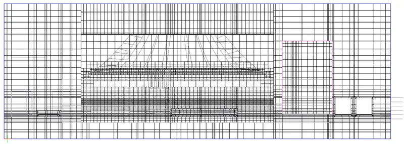
Visually the mesh appears to be fine. The non-conformal meshing applied to the different assemblies is preventing the bleeding of mesh.
Quality check
The following quality checks are performed to further assess the mesh quality:
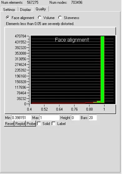
1. Face alignment: It is a measure of the relative face alignment between two adjacent elements in the mesh. The image attached below shows the face alignment histogram for different elements in the current mesh.
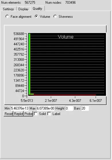
2.Volume: It measures the volume of all the elements in the mesh. The image attached below shows the volume histogram for different elements in the current mesh.
3.Skewness: It is a measure of how close to the ideal (equilateral/equiangular) a mesh element is. The image attached below shows the skewness histogram for the different elements in the current mesh.
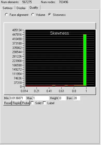
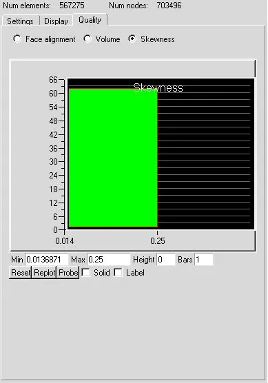
A skewness of 0 indicates that the mesh element is degenerate whereas a skewness of 1 indicates that the mesh element is ideal (equilateral/equiangular). For the current mesh the minimum skewness is 0.0136871 which indicates that no mesh elements are degenerate. However the image also shows that nearly 62 elements in the mesh have a skewness value less than 0.25 which indicates that they have a poor quality and need to be fixed.
Conclusion:
In the current project, the given Icepak model was modified to achieve better resolution of CAD objects and reduction in the overall mesh count, using multi-level meshing. The generated mesh was inspected visually and was also checked for quality using the three metrics: face alignment, volume and skewness. Based on the inspection results, it can be concluded that the modified mesh (multi-level mesh) was able to better resolve the CAD objects using much fewer elements than the initial mesh.