Week 5.2 - Multi Level Meshing
Objective:
For the given cad model optimize the mesh count and improve the mesh bleeding using Multi level meshing technique
Problem description:
1. Open and unpack the given hanging_node.tzr model.Without any modifications, the model results in about 700,000 elements.
2. Mesh count results from using the non-conformal meshing technique, which reduces mesh bleeding and mesh count. However, this mesh does not fully resolve the fine-level geometric features of the CAD objects.
3.You can reduce the mesh count and improve the mesh resolution on and around the CAD objects by using the multi-level meshing technique.
4.This procedure starts with a coarse background mesh and resolves fine level features through a series of successive mesh refinements. By using multi-level meshing and the uniform mesh parameters feature, you can reduce the mesh count to approximately 500,000 elements and improve mesh resolution.
Generate the Mesh:
Following steps are to bo
- Create non-conformal mesh assembly
- Use mesh separately option with slack values
- Use object parameters
- Use set uniform parameters and use average on 1 assembly, in multi-level meshing tab allow multi-level meshing up to level 2 for the objects.
- Use the same technique of 1
- Generate mesh.
- Observe in mesh reduction
- Do visual inspection
- Check for quality
- Create non-conformal mesh assembly:
1. Open and unpack the given hanging_node.tzr model in icepak
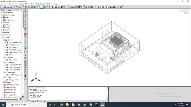
2.For cad models mesh type will be mesher HD and then generated mesh using coarse mesh parameters.
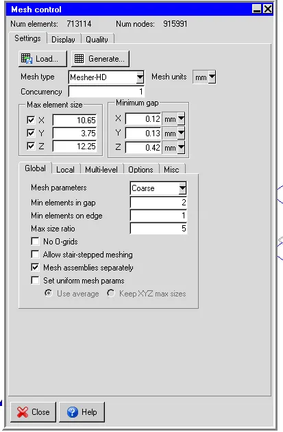
3.It generates No of elements=713114 and No of nodes=915991 and next performing non conformal mesh
4. pictures of intial mesh of model
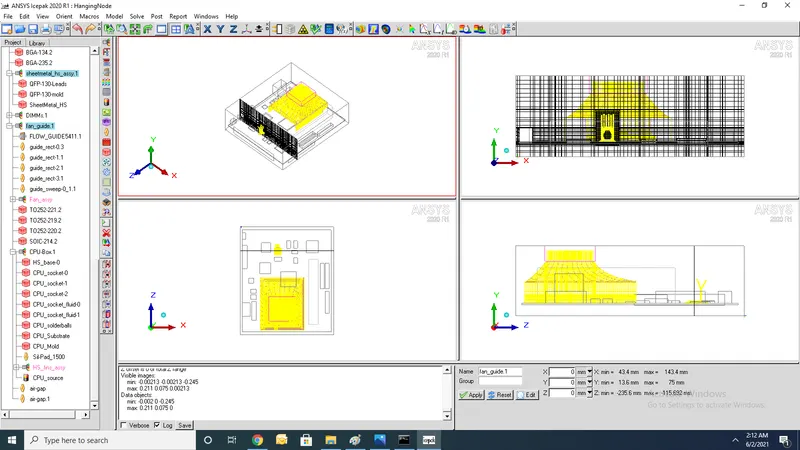
5.Intial cutplane mesh of fan guide
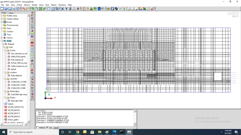
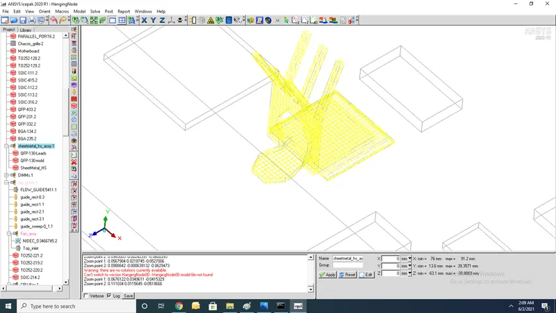
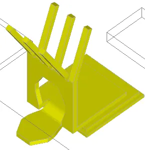
6. pictures of intialSurface mesh of sheetmetal assy
2.Use mesh separately option with slack value:
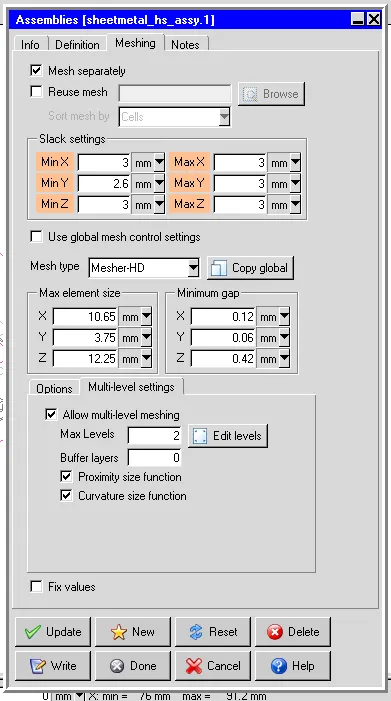
1.perform Non conformal mesh on sheet metal assay with slack values
2.In Non conformal slack variables must be postive but not zero
3. Two assemblies dont touch each other and must follow rules of assembly
4.use mesh separately is applied to sheet metal assy because of poor mesh bleeding
3.Use object parameters:
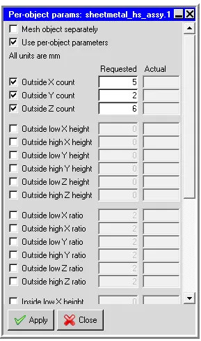
1.For this cad model object parameters are taken as 1/40 of co-ordinates x,y and z respectively
2.Due to poor mesh bleeding of sheet metal assay object parameters are provided
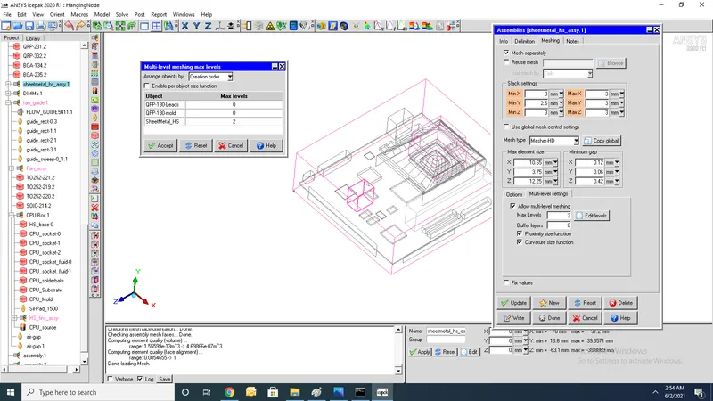
4.Use set uniform parameters and use average on 1 assembly, in multi-level meshing tab allow multi-level meshing up to level 2 for the objects
1.For sheet metal assy enable multilevel meshing Give max levels=2 and check mesh bleeding
5.Use the same technique of 1:
1.For Fan guide assembly apply same technique with max levels as 1
6.Generate mesh:
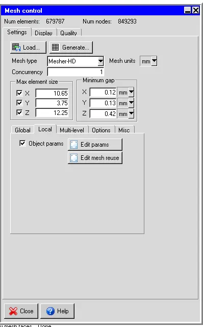
1.After generating multilevel mesh nodes and elements of model get reduced from No of elements=713114 and No of nodes=915991 to No of elements=679787 and No of nodes=849293
2.Picture of Fan guide assembly after multilevel mesh
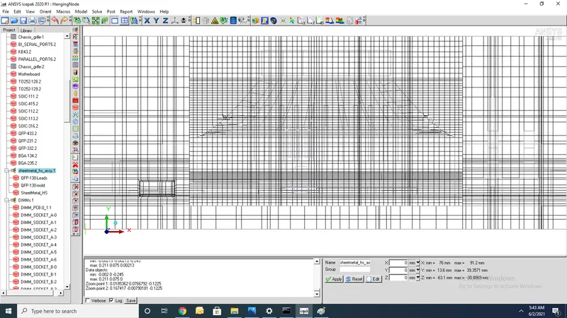
3.pictures of sheet metal assembly after multi level mesh
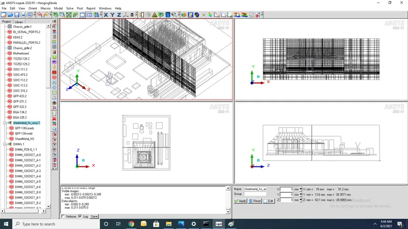
4.Pictures of cad model after multilevel mesh
7.Do visual inspection:
1. Check mesh bleeding and mesh size of cad model
2.Check any overlapping of bodies are present
3.Check mesh grid size
8.Check for quality:
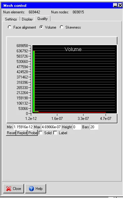
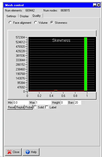
1.Face alignment:
1.Facealignment of icepak after multilevel meshing shown
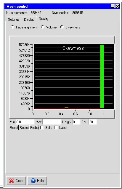
2.Volume:
3.Skewness:
Conclusion:
1.Multilevel mesh optimizes the mesh count and also reduces the meshing time of cad model
2.Improves quality of mesh in the given cad model