Week 5.1 - Non-Conformal Meshing and Solving a Cold plate model
Non-Conformal meshing of cold plate model:
Objective:
To perform Non-Conformal meshing of cold plate model:
Non conformal mesh :
1.Non conformal mesh basically required inorder to reduce mesh count
2.To get good resolution,quality of mesh of different curvatures and parts you will perform Non-conformal meshing.
Problem description:
1. The model includes two heated plates, cooled by water circulating inside the cold-plate cavity.
2.As well as by air driven by natural convection externally.
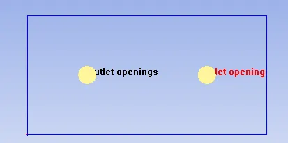
3.Consists of Two Blocks one is solid & fluid blocks and also two openings one opening is inlet with watervelocity in x-direction (0.2m/s) and other is outlet opening
Geometry setup:
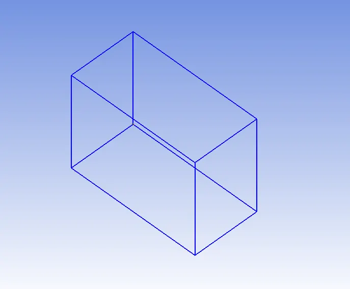
1. Cabinet Size: 400 mm X 300 mm X 200 mm
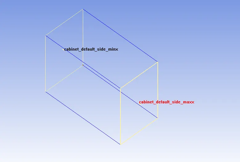
2.Cabinet opening: MinX and Max X
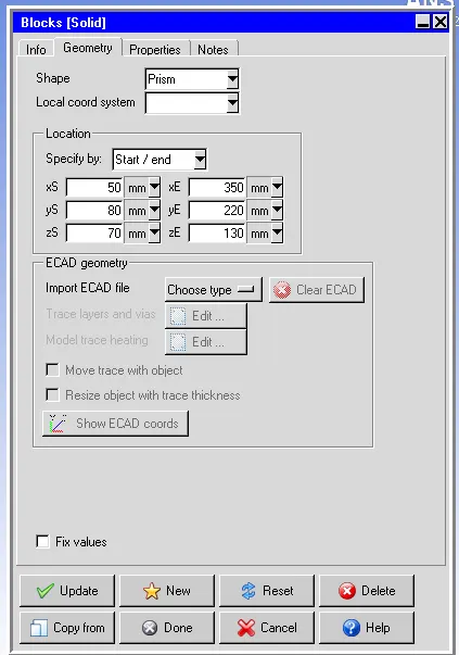
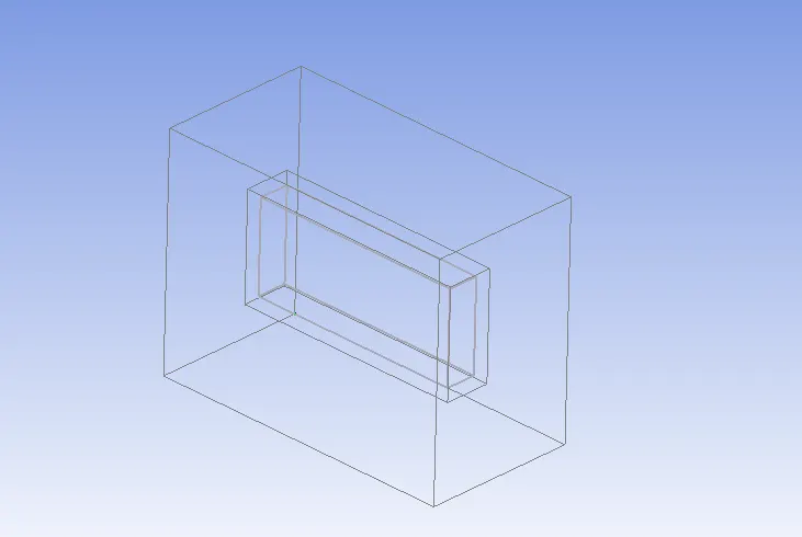
3. Cold plate solid block: start (50 mm, 80mm, 70 mm), End (350mm, 220 mm, 130 mm) made of aluminum extruded
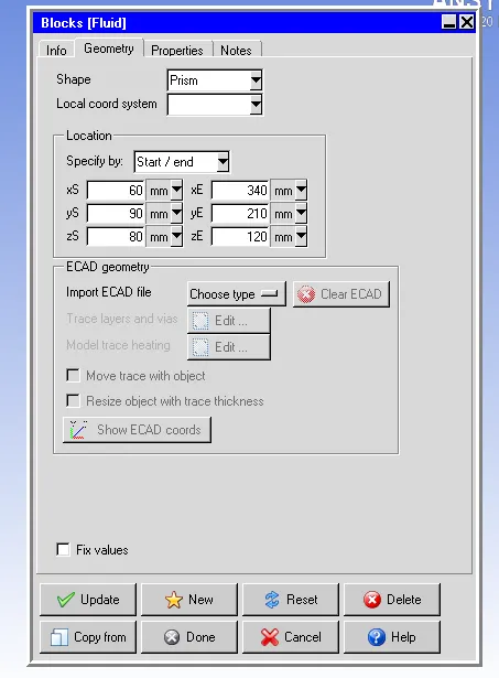
4. Cold plate fluid block: start (60 mm 90mm, 80 mm), End (340mm, 210 mm, 120mm)
5.Picture of both solid and fluid block
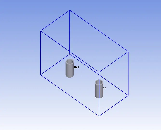
6. Inlet and outlet pipes
Incoming pipe: thickness : 5mm, connected @ (100mm, 0 mm, 100mm) and radius 15 mm, the inlet water velocity is 0.2 m/s
Outgoing pipe: thickness : 5mm, connected @ (300mm, 0 mm, 100mm) and radius 15 mm
6. Inlet and outlet openings
7. Source:
Plate 1: conducting thick 10mm, 200W, located at 60mm having dim (260 mm X 100 mm) in Z plane
Plate 2: conducting thick 10mm, 200W, located at 130mm having dim (260 mm X 100 mm) in Z plane
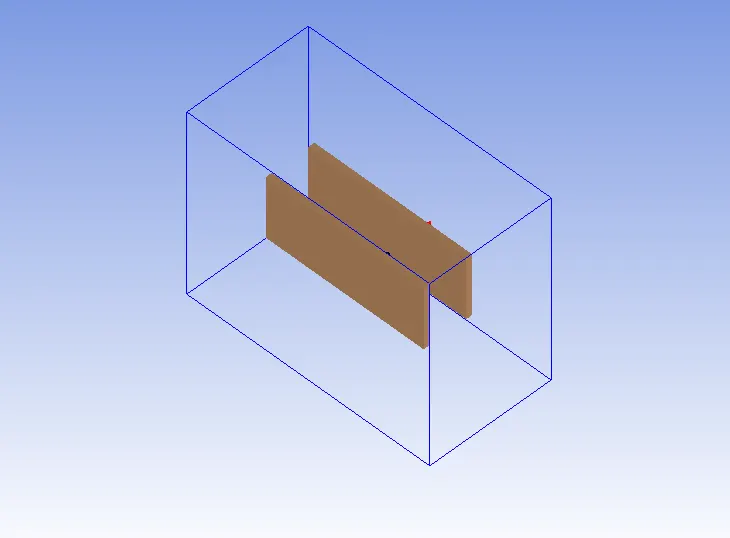
8.Final geometry
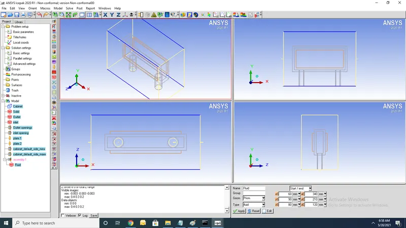
Meshing:
1. For Non-conformal meshing we use Hexa unstructured
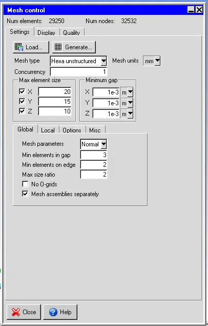
1.Applying local refinment of mesh by editing parameters
2.Create assembly for fluid block to increase mesh count
3.Increase values of x,y,z counts x=30,y=16,z=10
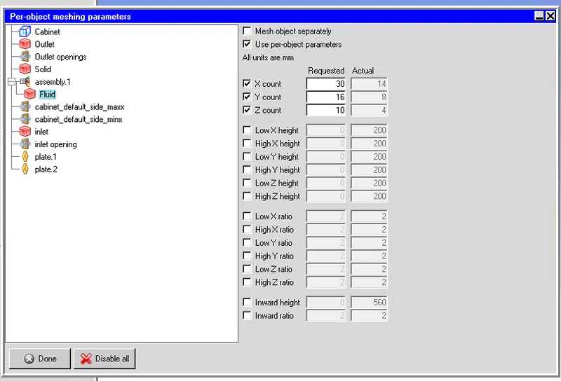
4.Mesh count increase after applying use per object parameters
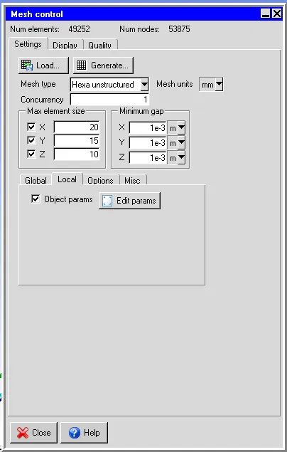
Slack settings:
1.Adding slack region that propagates finer mesh with in assembly by distance
2.Slack setings are difined with min,max x,y,z
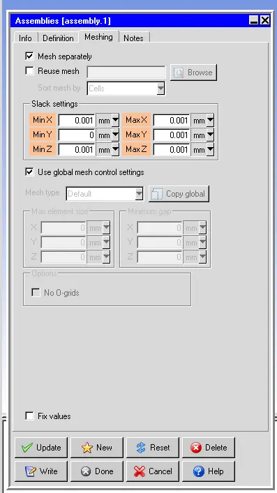
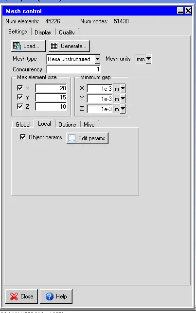
5.After applying slack variables then mesh count of assemblies get decreased
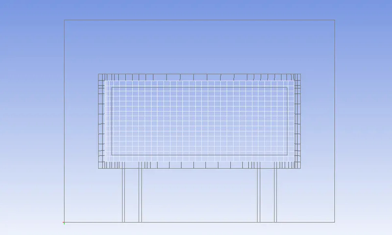
6.Non-conformal meshing of assemblies
Numerical setup:
1.Problem setup wizard:
1.Solve for velocity and pressure
2.Solve for temperature
3.Flow is buyonacy driven (Natural convection)
4.Use Boussinesq approximation
5.Set flow regime to be turbulent
6.Zero equation(Mixing length)
7.ignore heat transfer due to radiation
2.Basic parameters:
1.Set gravity in negative x direction
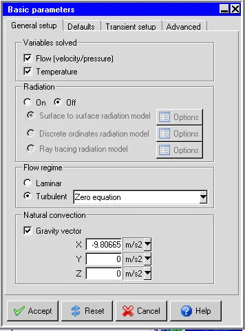
2.Transiant setup
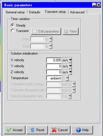
3.Solution settings:
1.Basic parameters
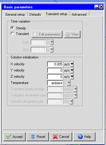
2.Advanced settings
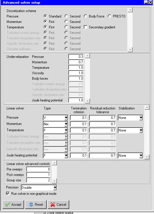
4.Monitor points
1.Set monitor points by using points at Min,Max openings of cabinent
2.Set monitor points by using points at assembly,inletpipe
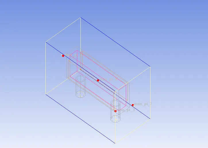
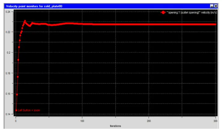
Velocity monitor point:
Velocity& Temp contour: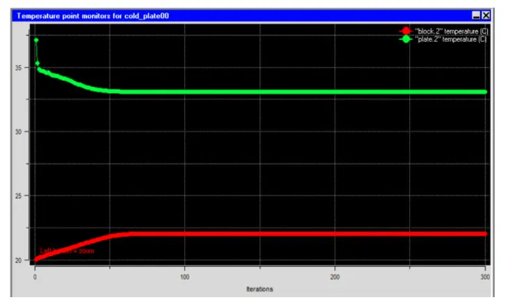
Residul plots:
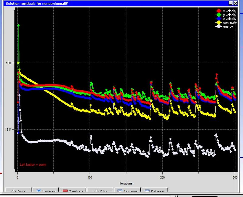
Contours:
1.For post-process results select iso surface and Z plane through center find contours and vectors
Temperature contour:
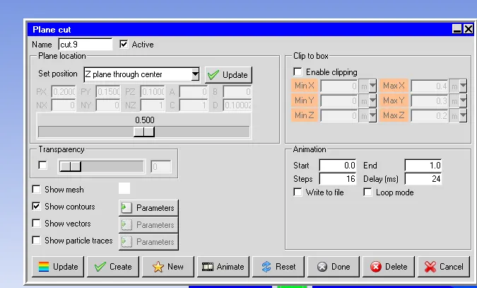
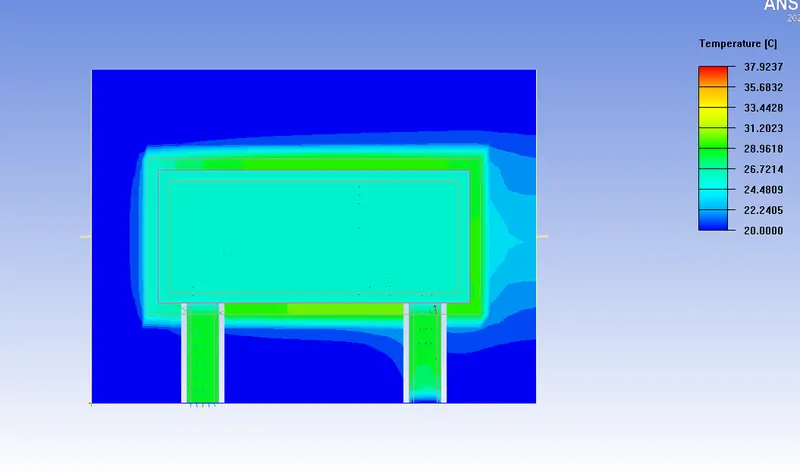
1.Max temp obseved as 37.9237 C
Velocity vectors:
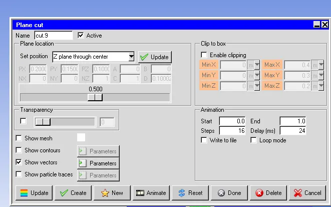
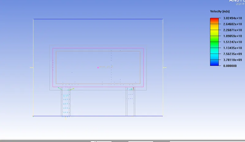
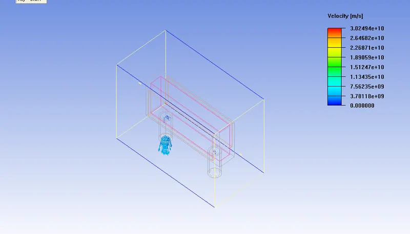
1.max Velocity observed as 3.02 10^10
Object face: