Week 4 -Wire Bending Challenge
Aim : perform an analysis to simulate the bending of a wire in ANSYS. use Copper Alloy (Non Linear), Aluminium Alloy (Non-Linear), and Magnesium Alloy (Non-Linear) for the wire alone
Procedure:
OPen ANSYS workbench and open static strictural module.
open engineering data and select material like stuctural steel, Copper alloy NL, Aluminum Alloy NL, And magnesium alloy NL.
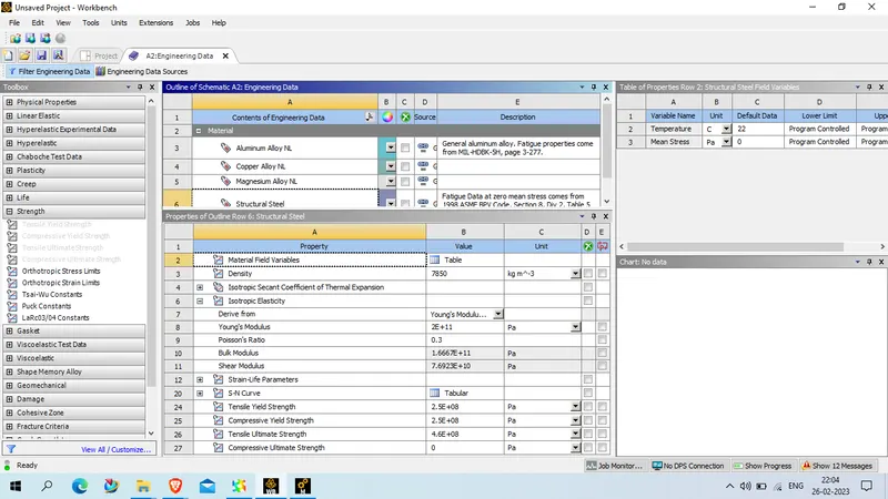
The mechanical property of stuctural steel is as given below
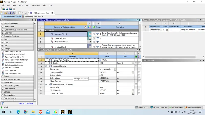
Mechanical property of aluminum alloy NL is as given below
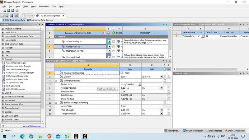
Mechanical property of copper alloy NL is as given below
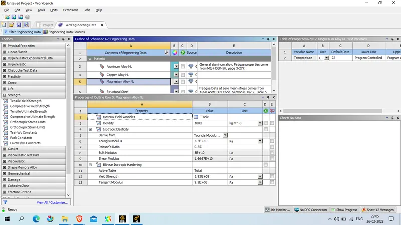
The mechanical property of Magnesium Alloy NL is as given below
NOw close the engineering data and upload geometry in spacecliam . and open spaceclaim using edit option , we check geometry as we found all good to proceed we close the spaceclaim and update model, and open mechanical model
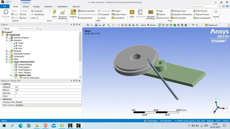
now expand the geometry and rename the component for better conveninet
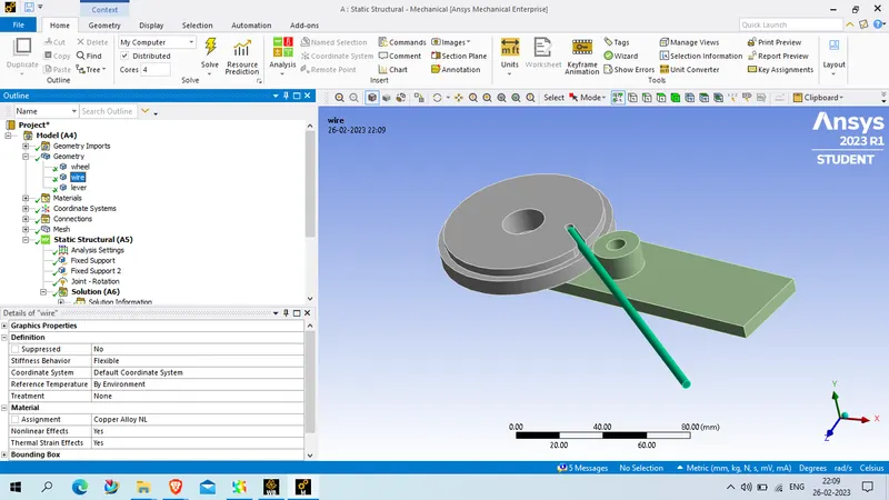
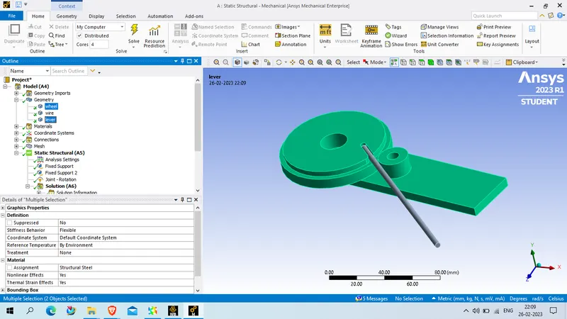
and apply copper alloy NL to wire and rest two component structural steel material
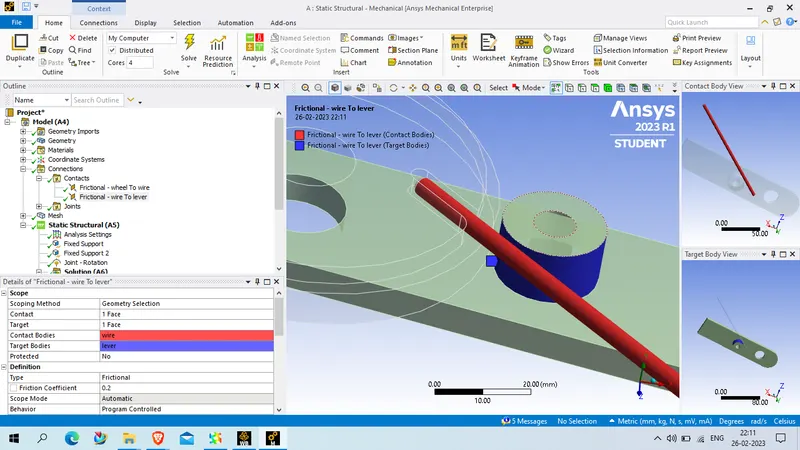
for contact :
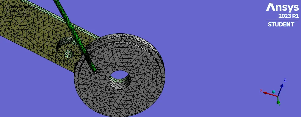
1. frictionaless contact between wheel and wire as shown as below
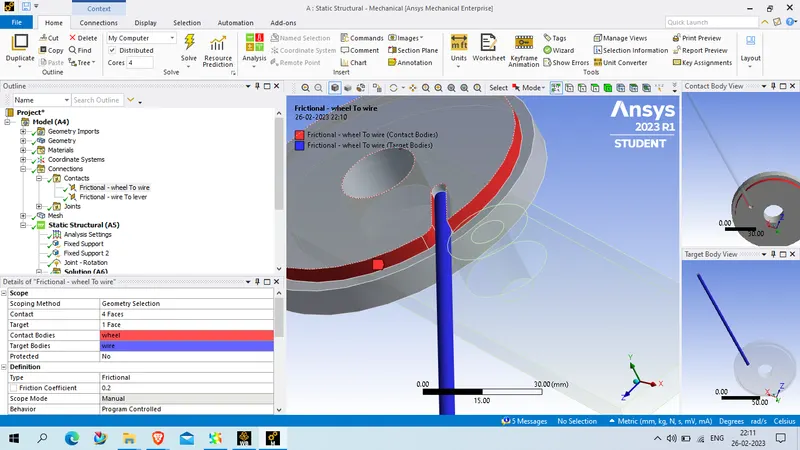
2. frictionless contact between wire and roller
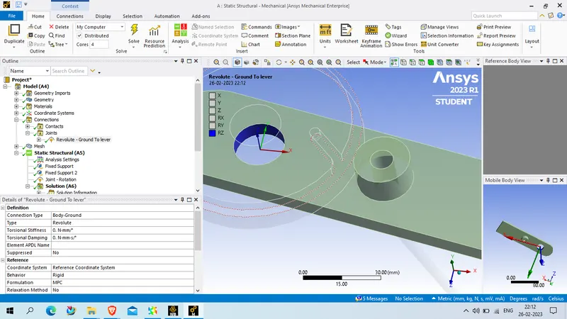
3. deploy a revolute joint to the roller as shown below
connection Type : body to ground
Type: revolute
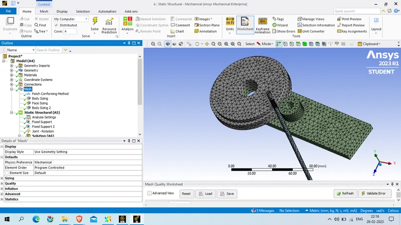
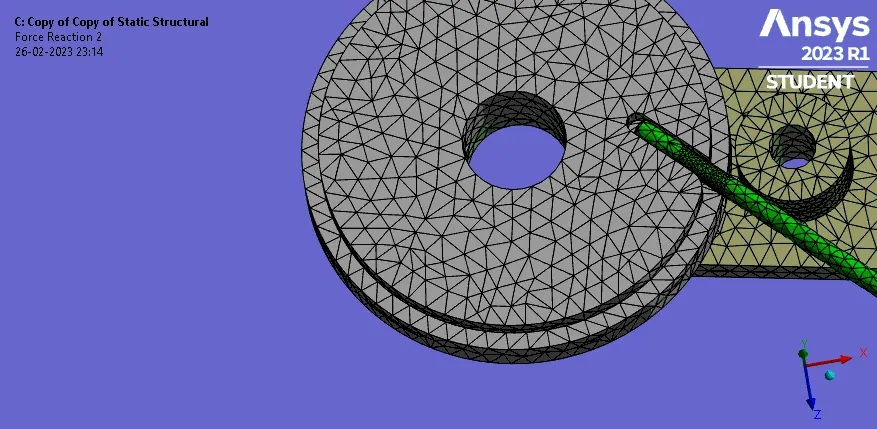
for mesh : we use tetrahedron mesh using patch conforming algorithm
wheel and roller with element size as 4 mm/
contact surface between wire , roller and wheel , element size will be 2.2 mm
and wire mesh will be mesh with influence of sphere with the radius of 7 mm and element size as 0.8 mm
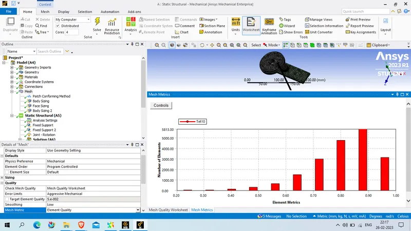
check mesh quality: mesh quality worksheet
error limit: agressive mechanical
target element quality : 5E-002
Smoothing : Low
The statics of mesh are gven below
The number of node : 32056
number of element : 19174
the element quality as given below
now for analysis setting we use 8 step
for step no 1
auto time steping : on
define by : time
initial time step: 0.1 s
min time step 0.01 s
max time step : 0.2 s
solver type : direct
weak spring : program controll
Large deflection : on
solver pivot checking : Program controll
for output controll
set all parameter as yes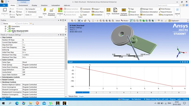
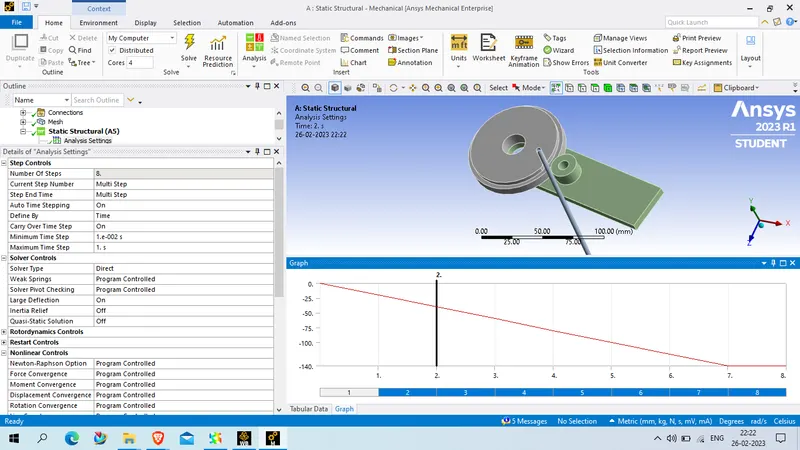
for 2nd to ith step
auto time steping : on
define by : time
initial time step: 0.1 s
min time step 0.01 s
max time step : 1 s
solver type : direct
weak spring : program controll
Large deflection : on
solver pivot checking : Program controll
for output controll
set all parameter as yes
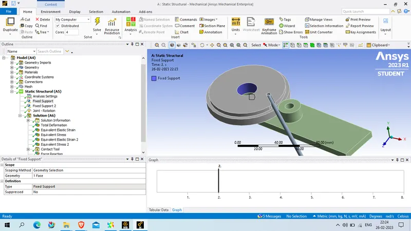
now deploy the fixed load to wheel as per given below
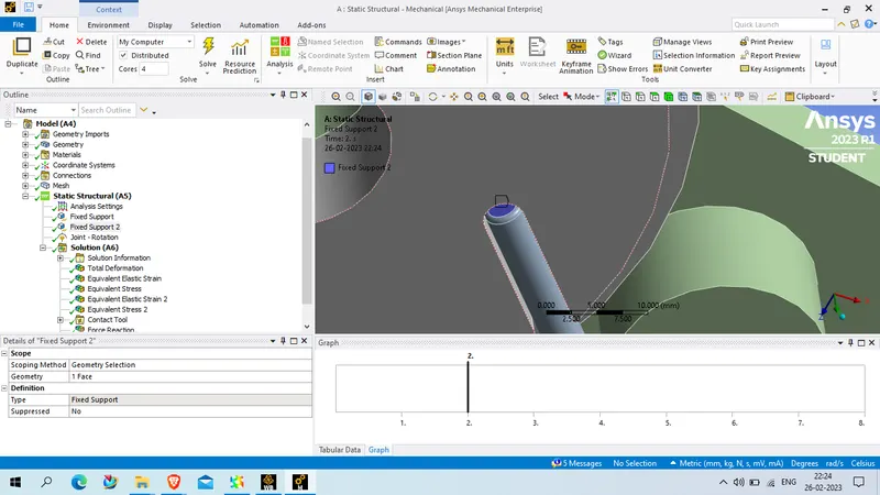
also deploye fixed load support to wire end to avoid slip as shown below
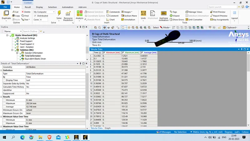
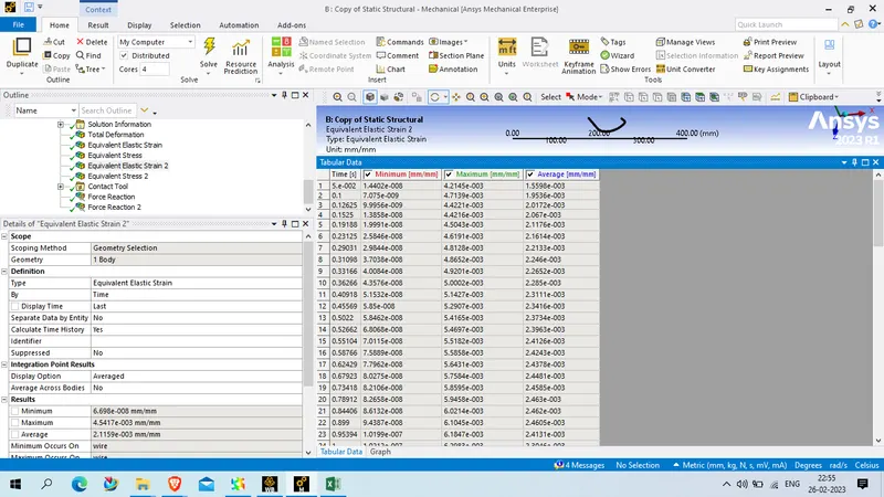
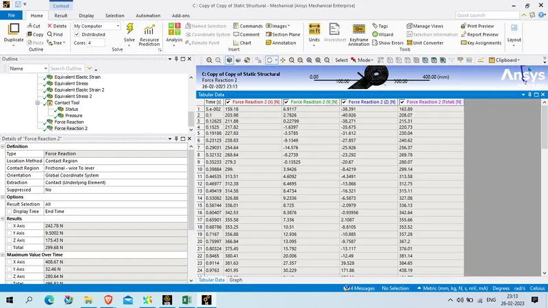
now deploy a rotation load to the lever with magnitude handle by tubular data , the details of tubular data is given below
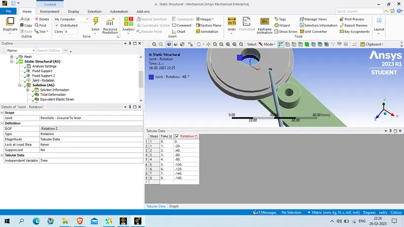
NOw list out required uotput from simulation and run
Picture :
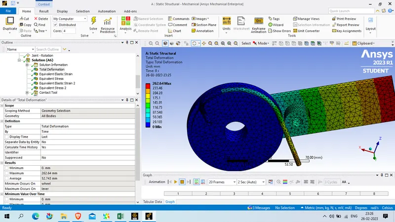
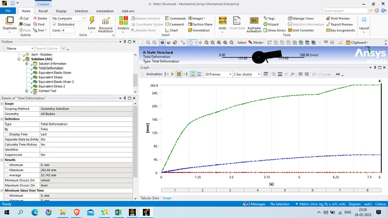
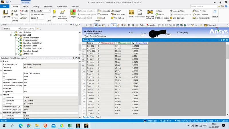
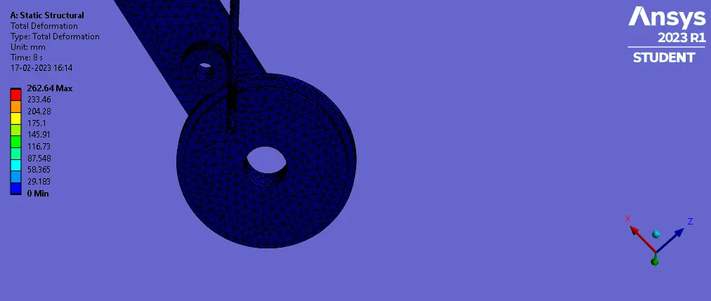
Total deformation
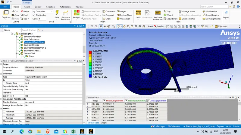
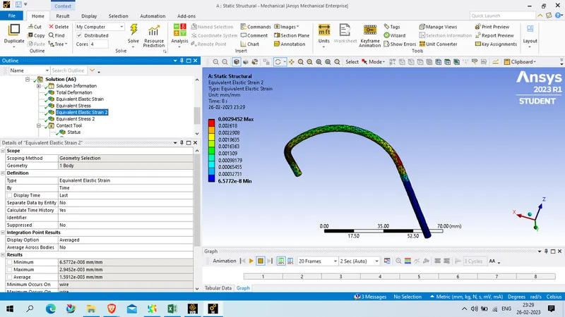
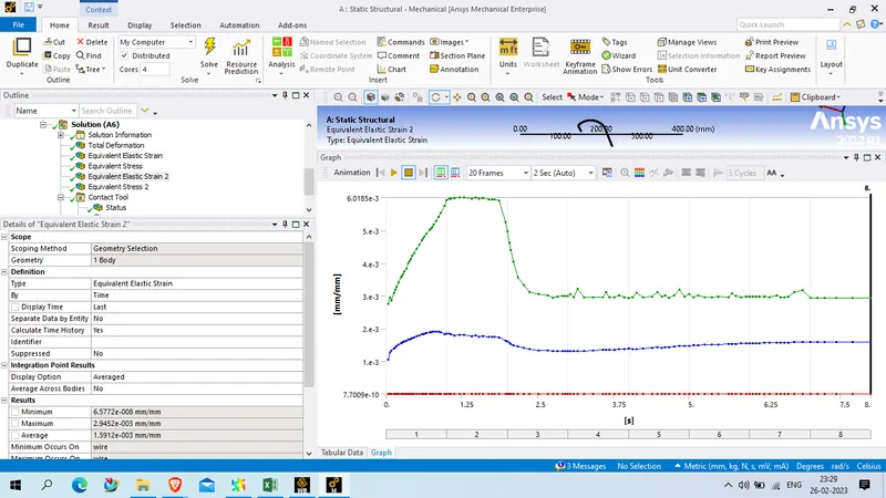
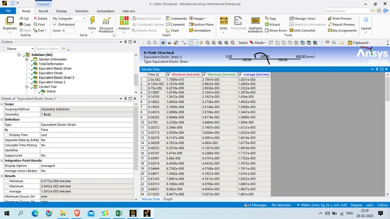
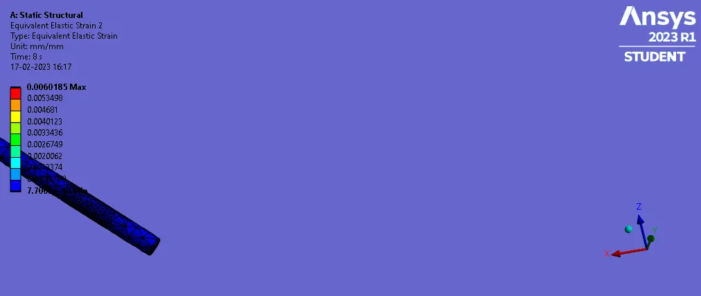
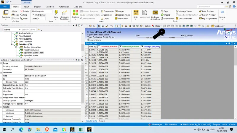
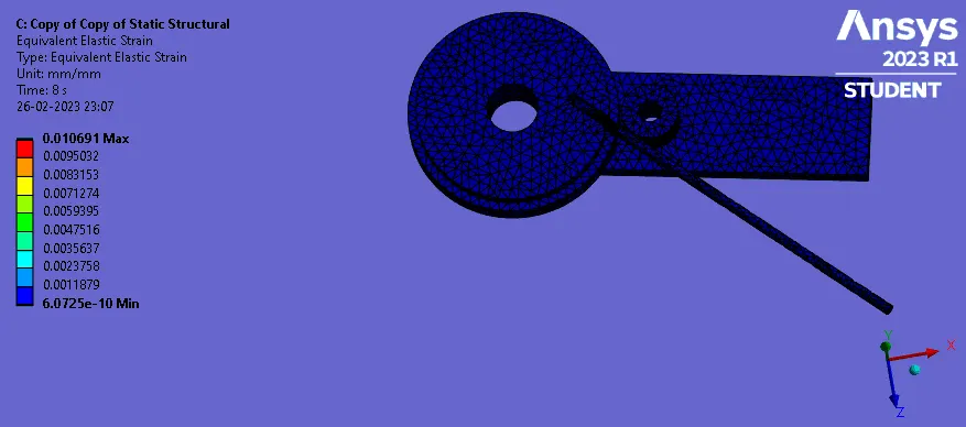
Equivalent elastic strain
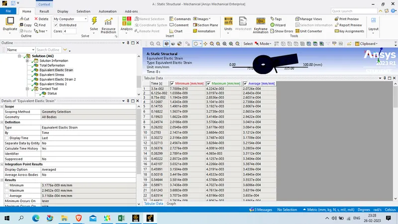
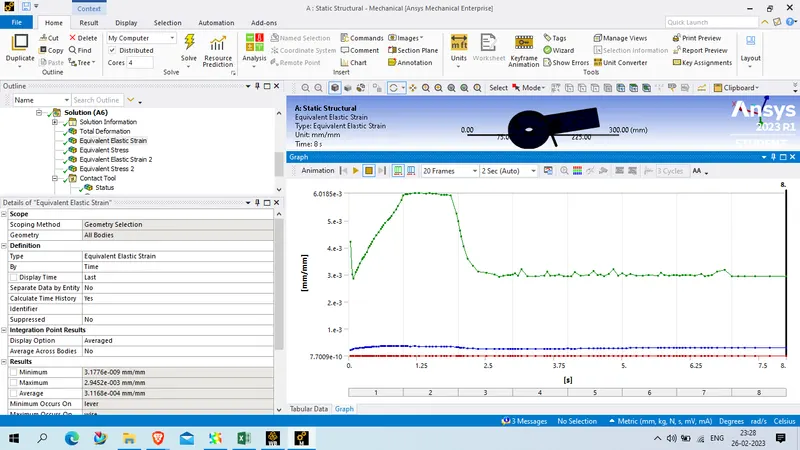
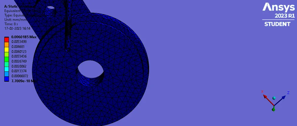
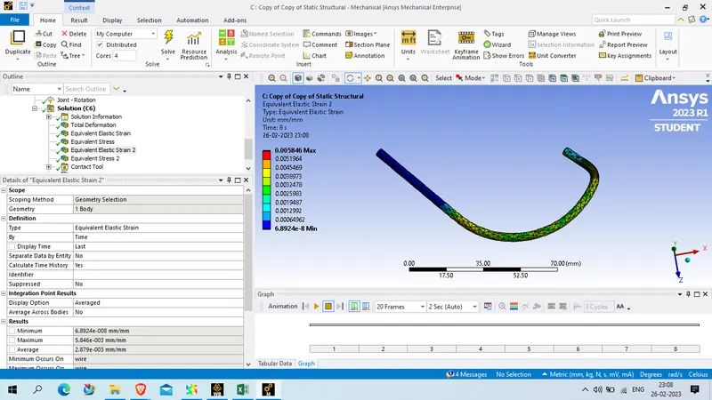
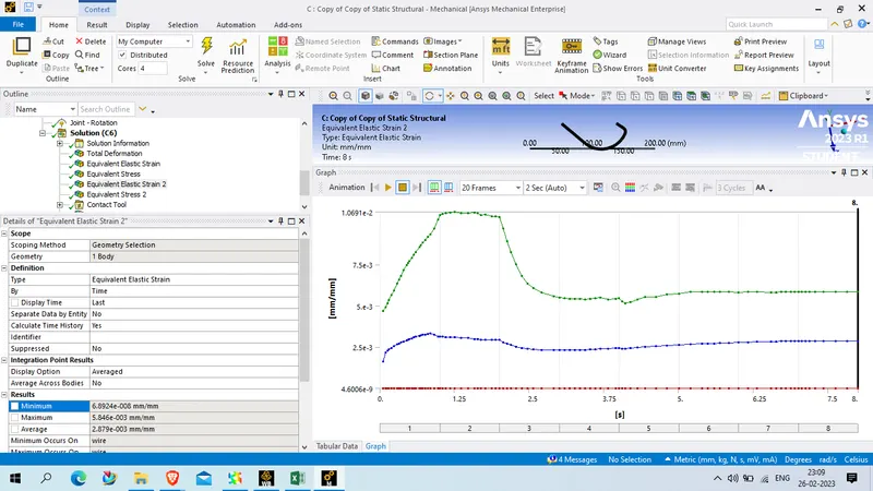
Equivalent strain on wire
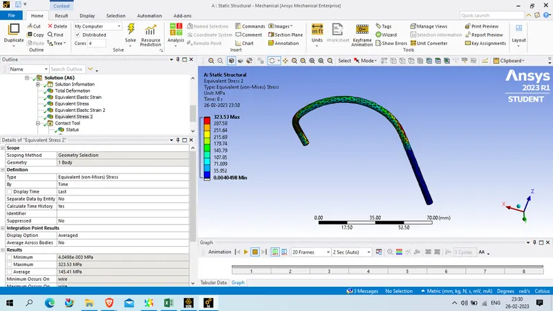
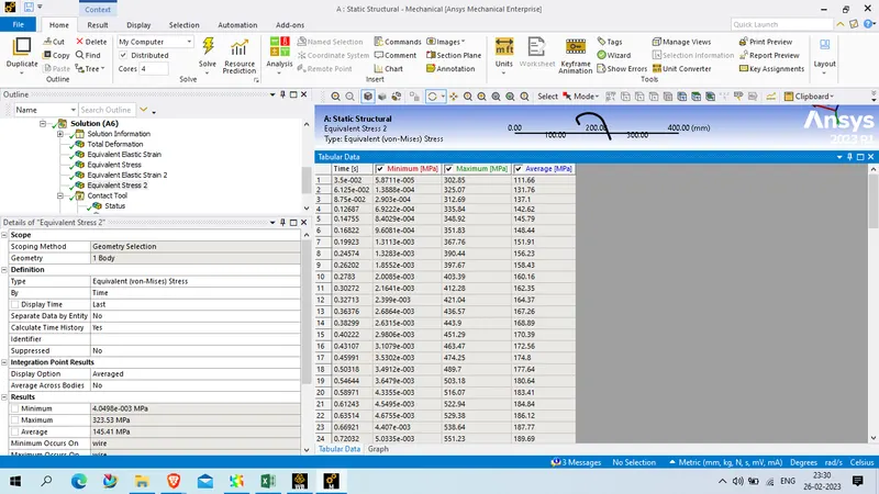
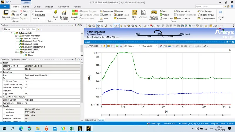
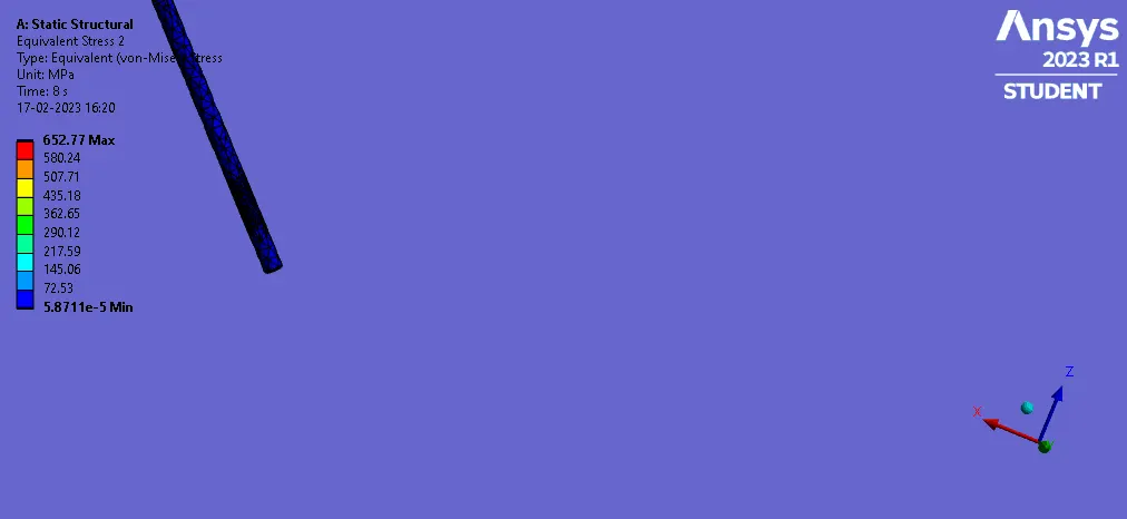
Equivalent stress
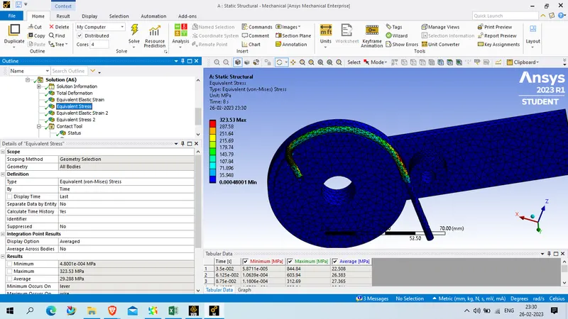
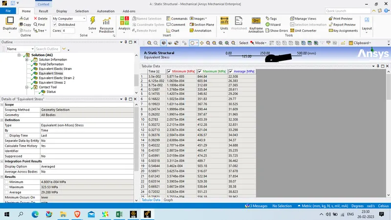
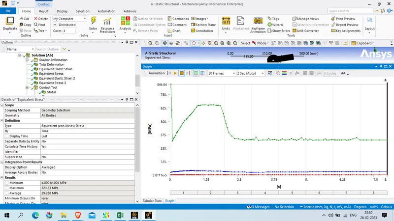
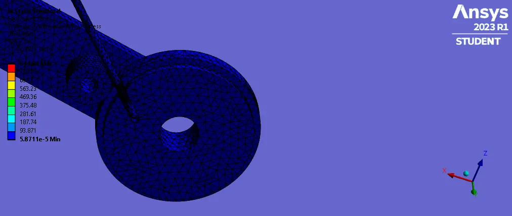
Equivalent stress on wire
'
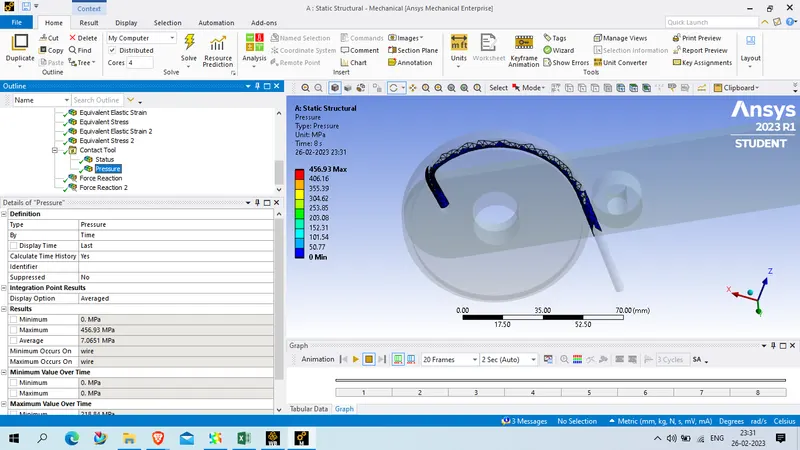
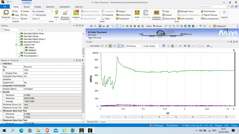
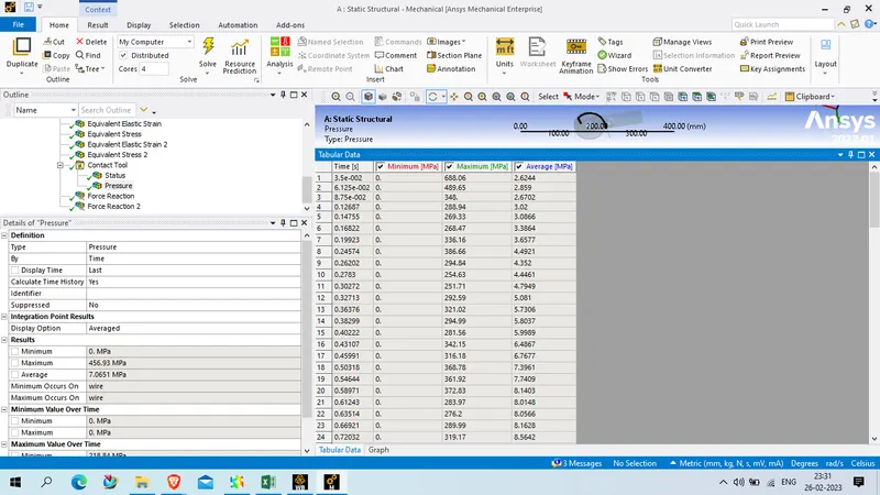
COntact pressure
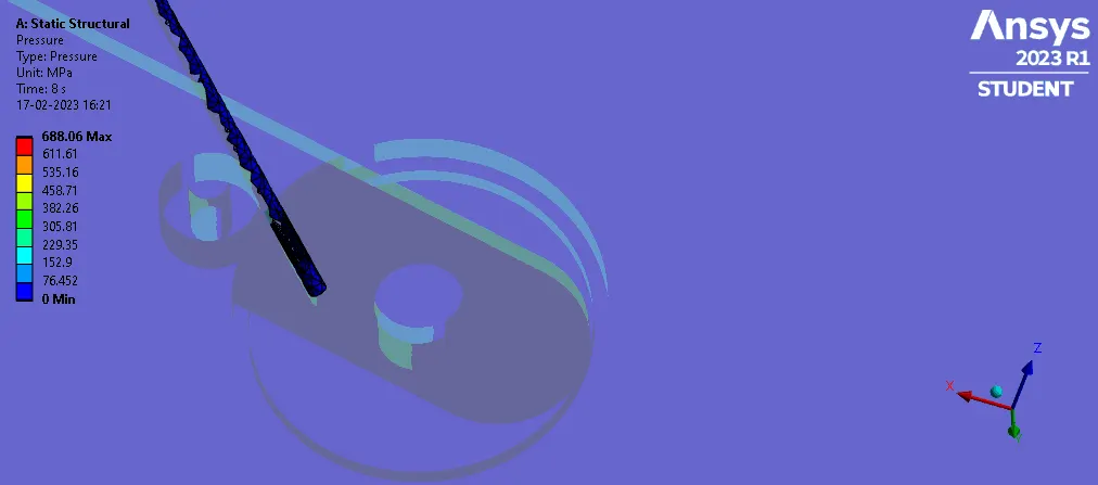
Frictional force reaction wheel to wire
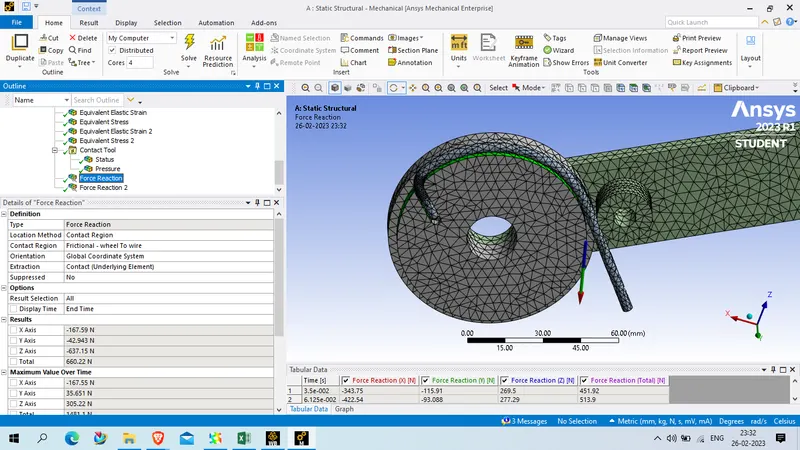
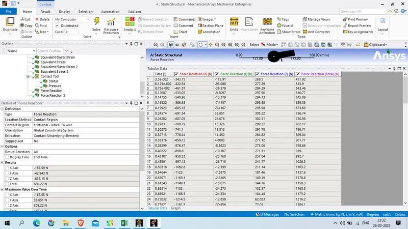
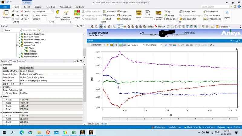
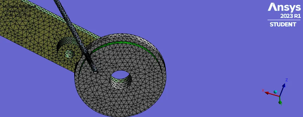
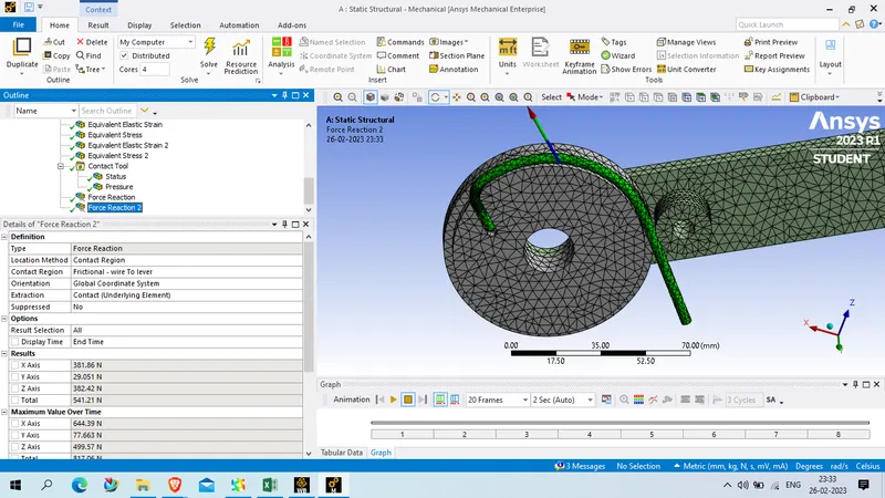
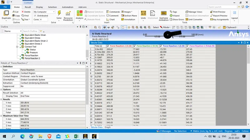
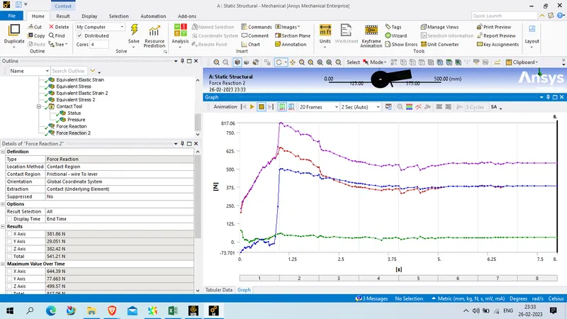
Frictional force reaction wire to lever
Case 2:
WE change wire material as aluminum alloy NL
rest setting will be same as previous case only analysis setting time step will be change as belwo
for 1st step
Initial time step: 0.05 s
Min time step : 0.01 s
max time step : 0.5 s
For 2nd to 8th step
Min time step : 0.05 s
max time step : 0.5 s
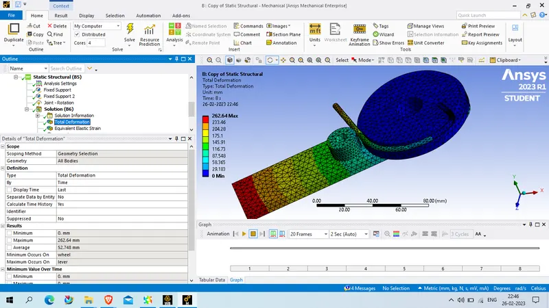
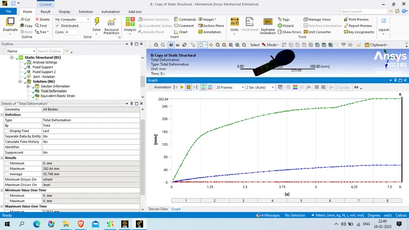
Picture :
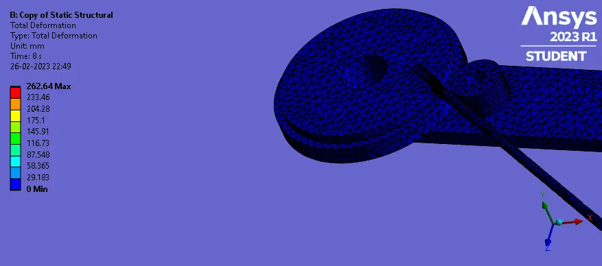
total deforamtion:
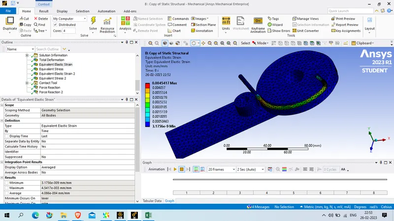
Equivalent elastic strain:
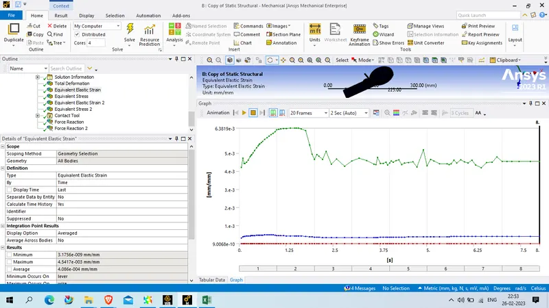
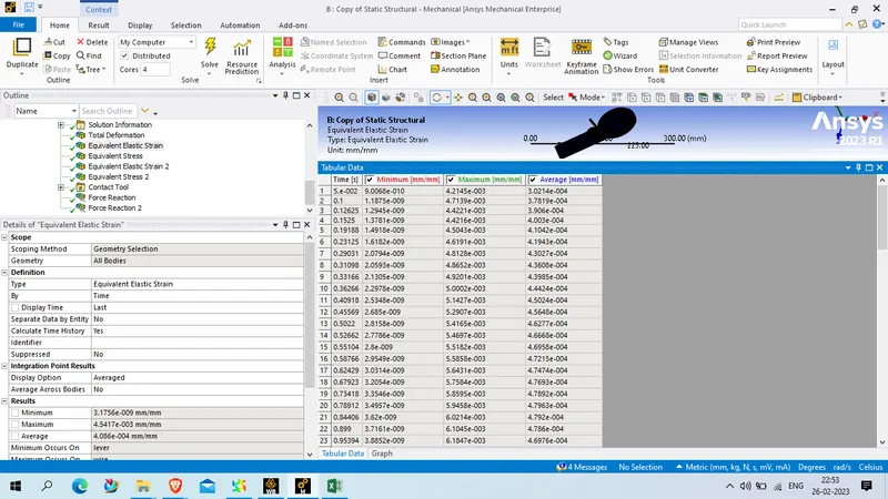
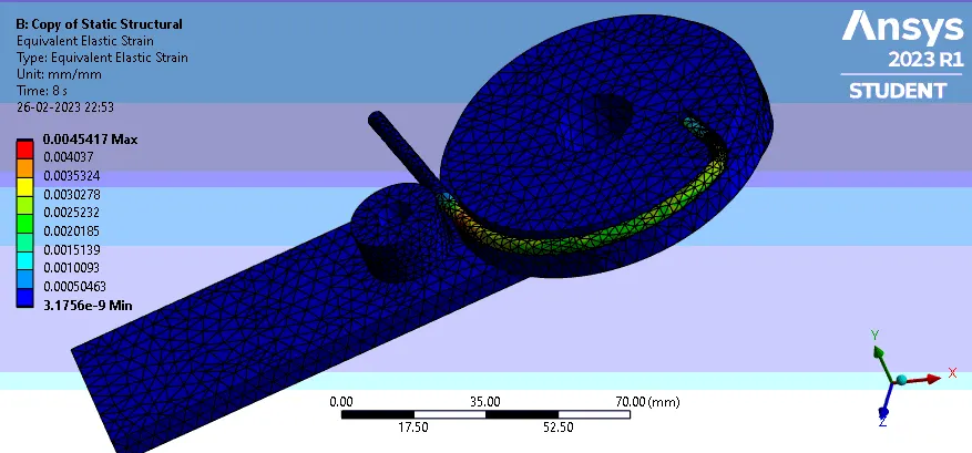
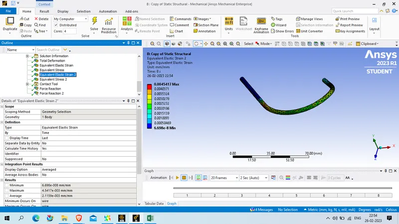
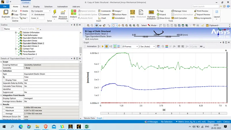
Equivalent strain on wire :
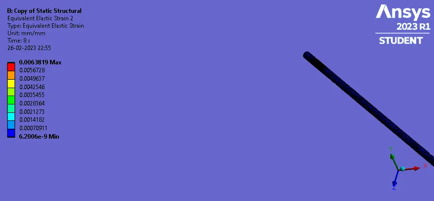
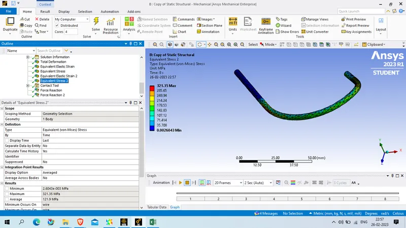
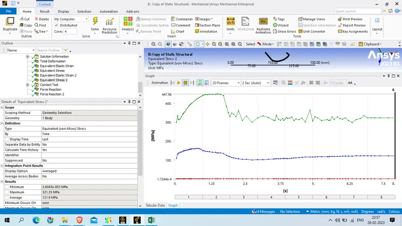
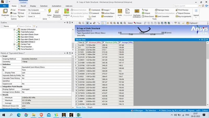
Equivalent stress
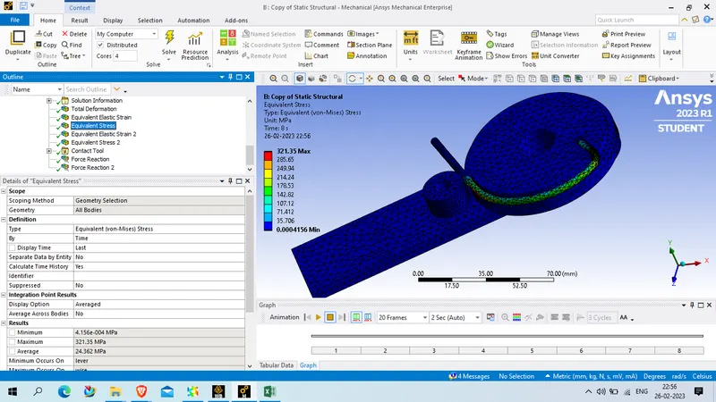
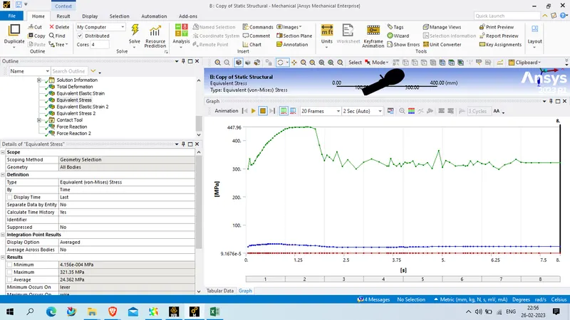
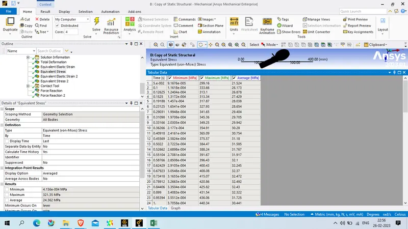
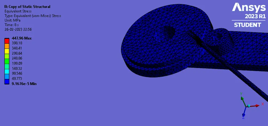
Equivalent stress on wire
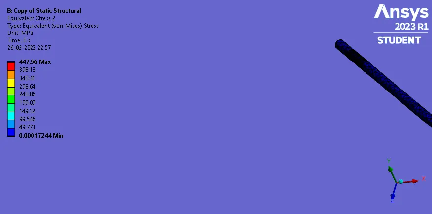
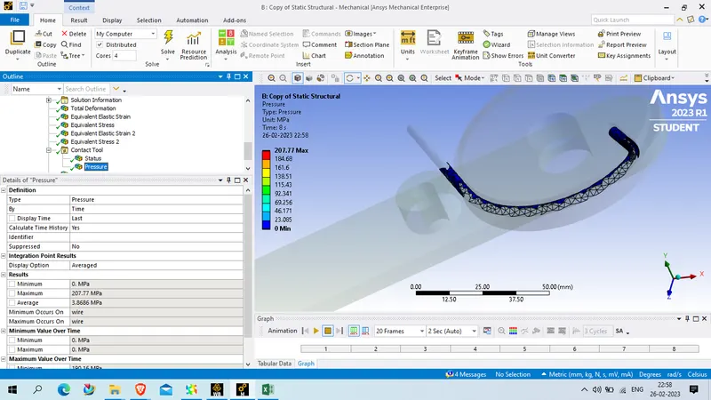
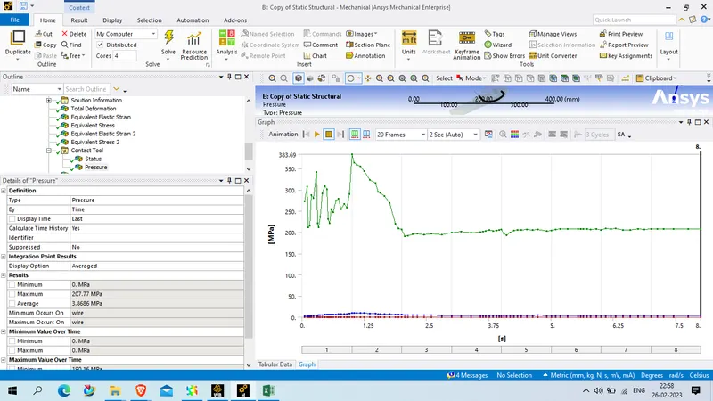
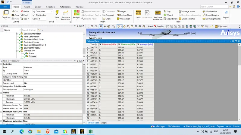
COntact pressure
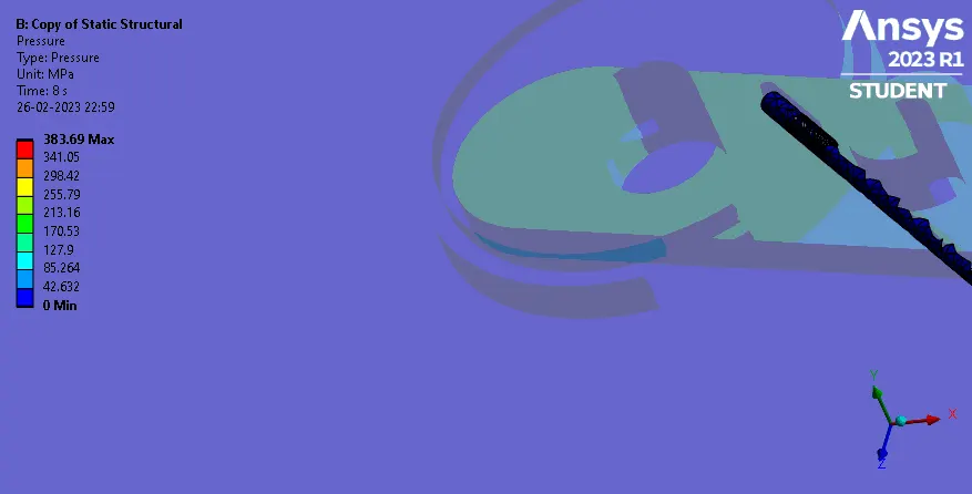
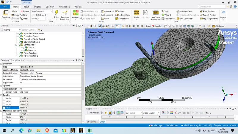
Frictional force reaction wheel to wire
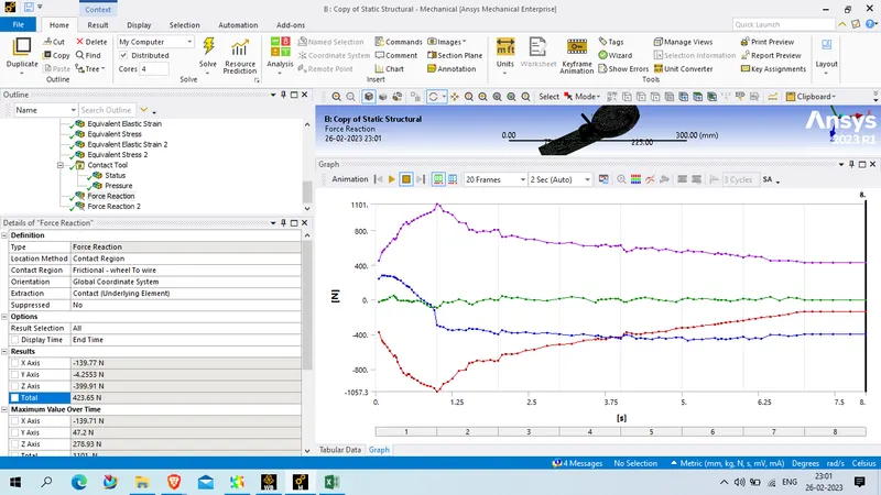
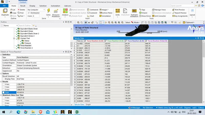
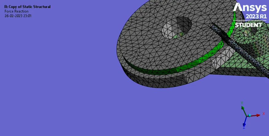
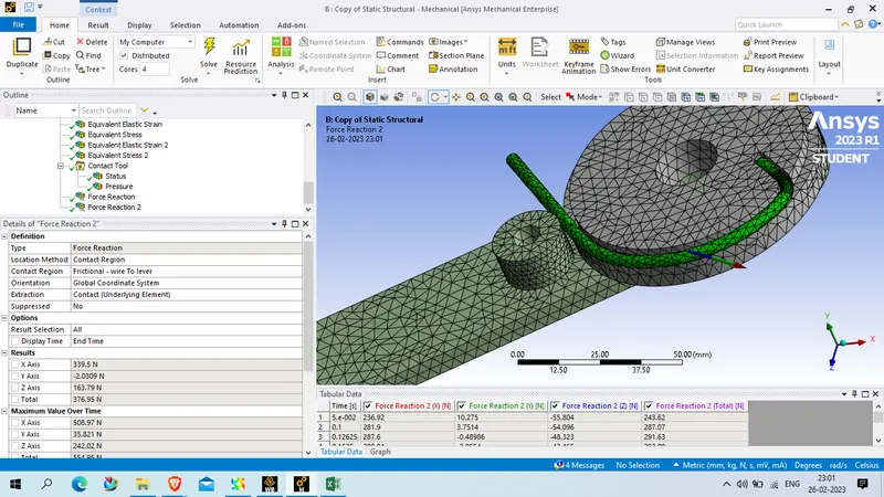
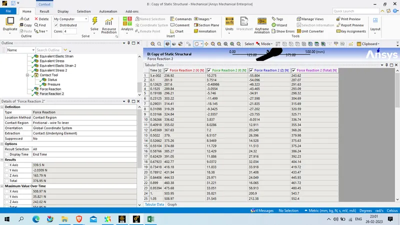
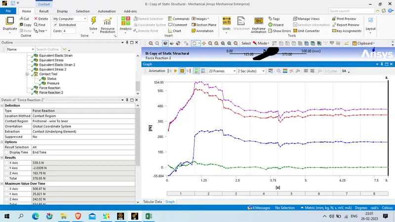
Frictional force wire to lever
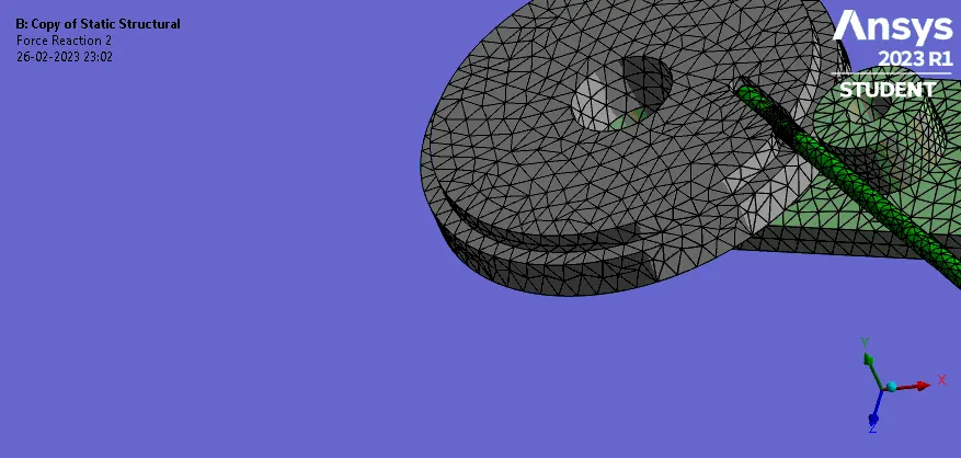
Case 3 : Wire material is magnesium alloy NL
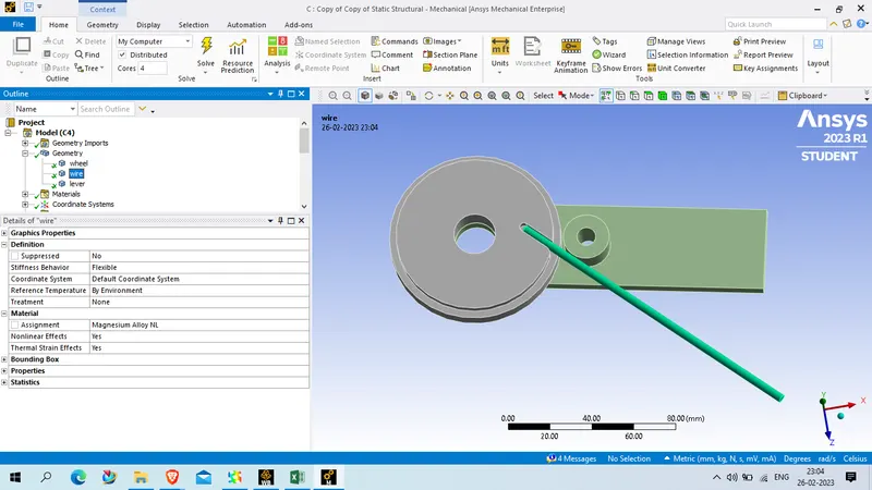
rest all the setting will be same as case 2
Picture :
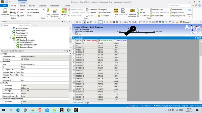
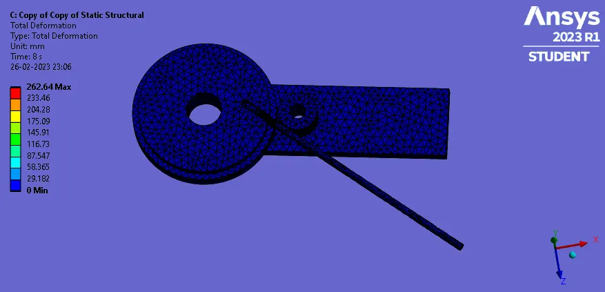
Total deformation
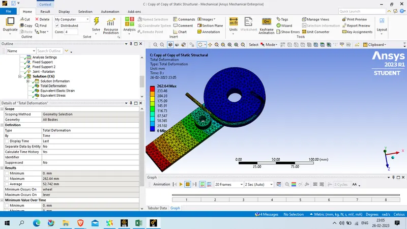
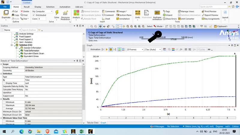
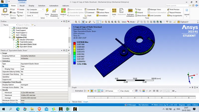
Equivalent strain
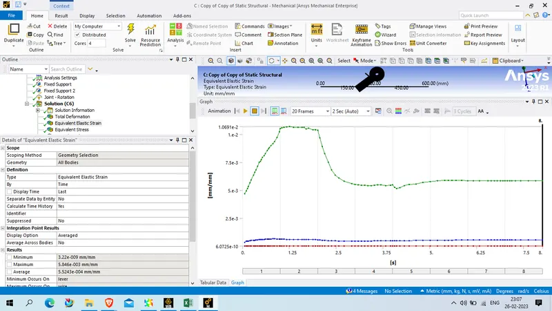
Equivalent strain on wire alone
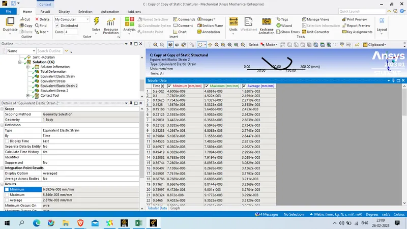
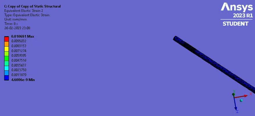
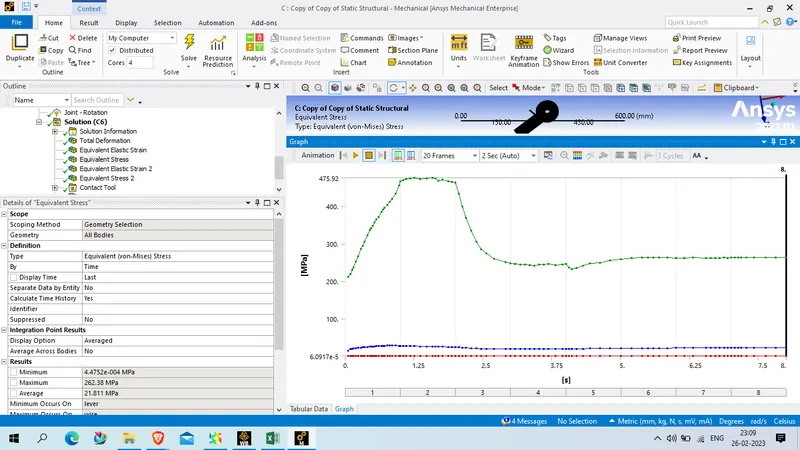
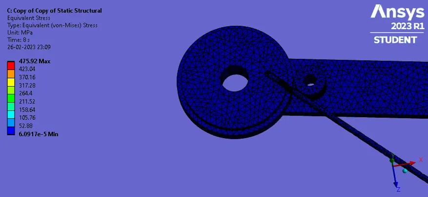
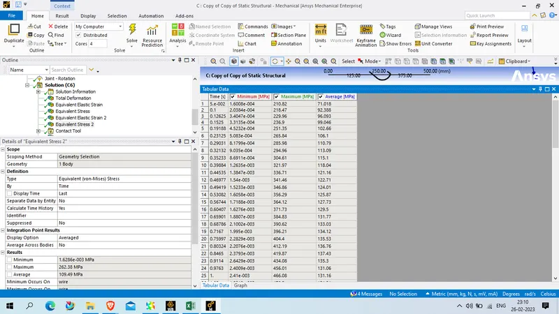
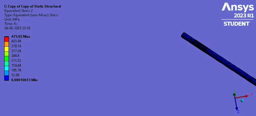
Equivalent stress
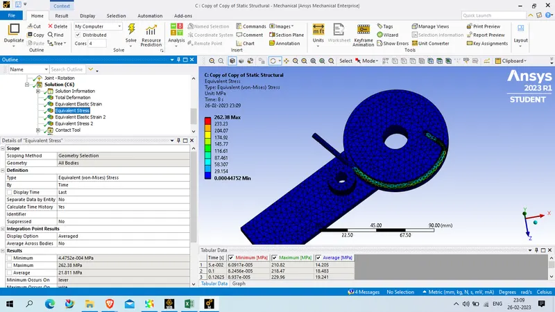
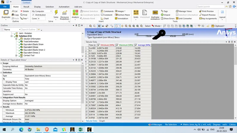
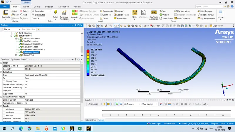
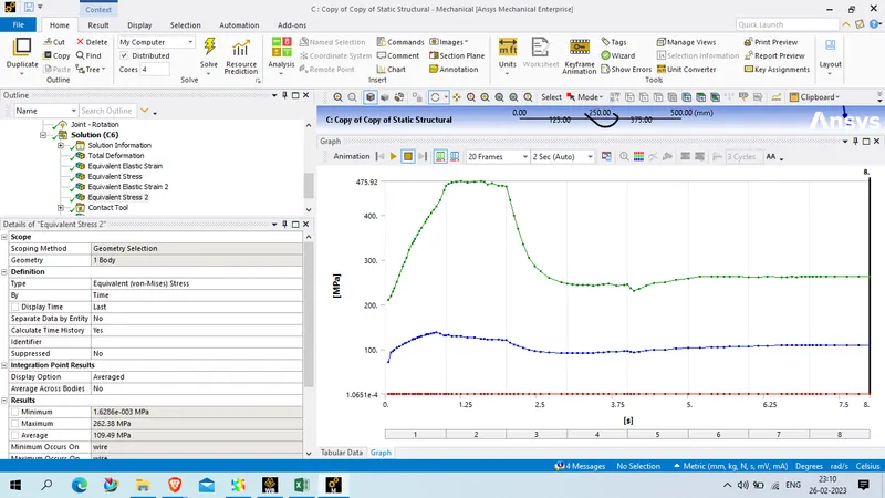
Equivalent stress on wire
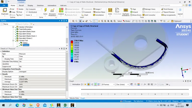
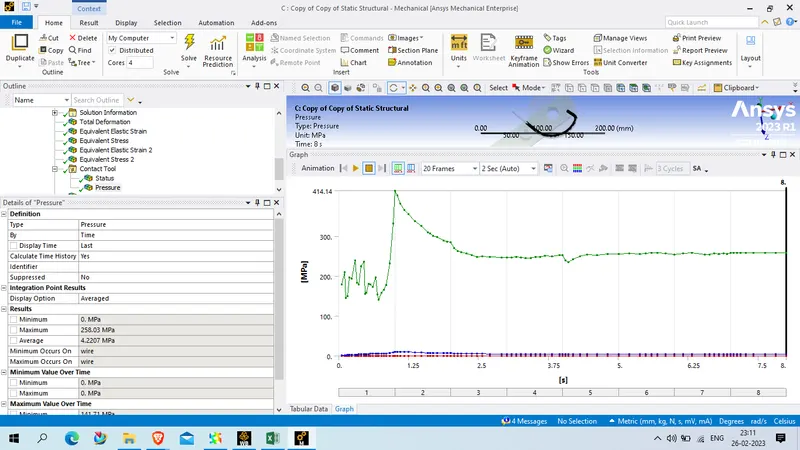
Contact pressure
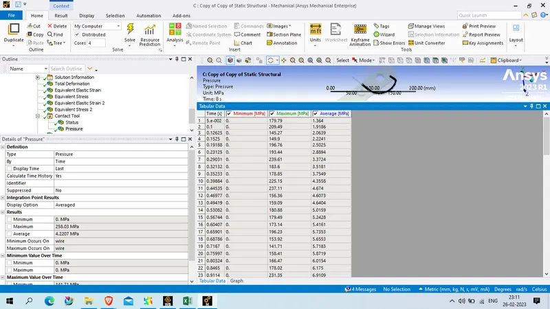
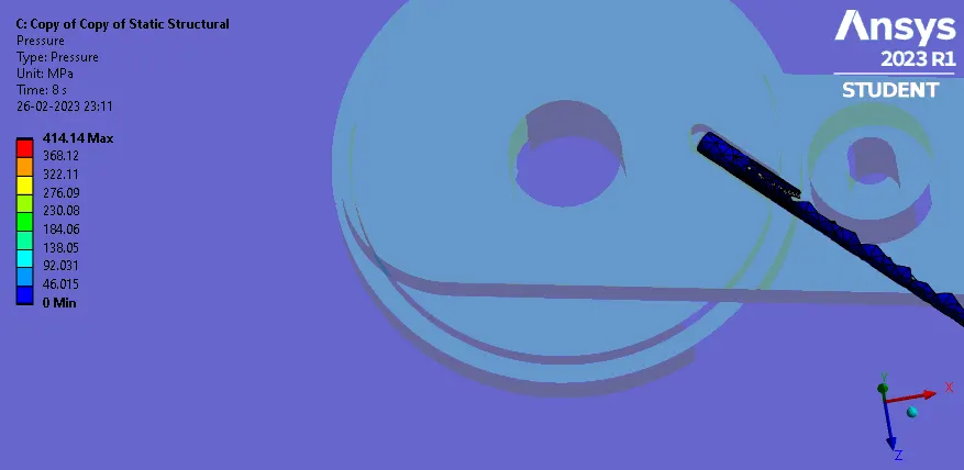
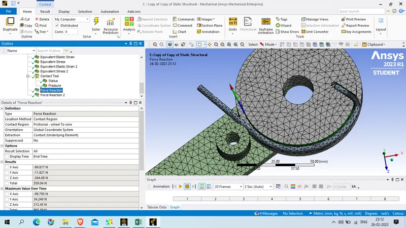
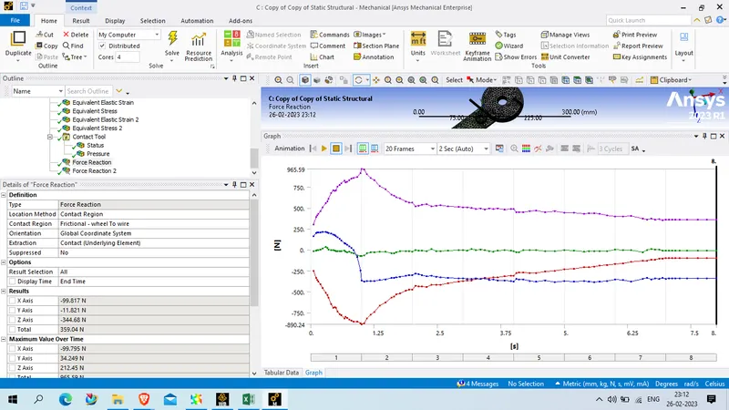
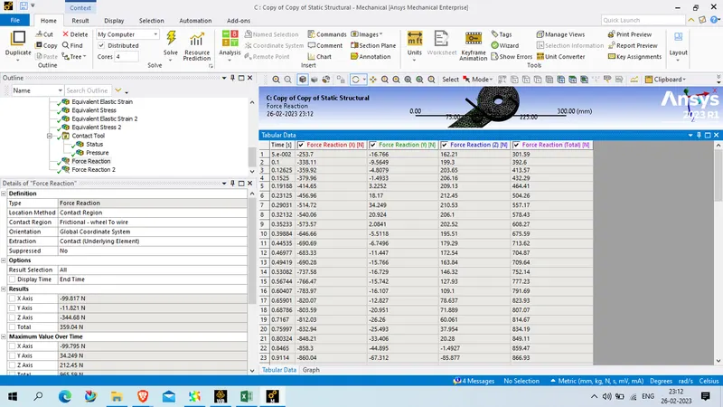
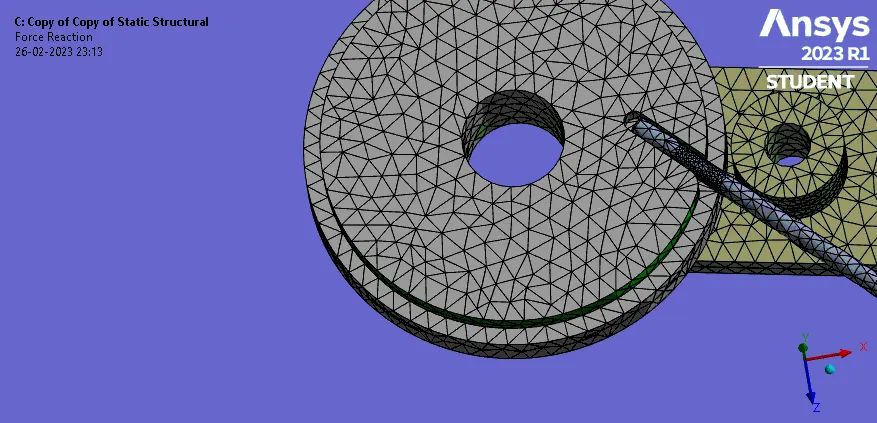
Force reaction at wheel to wire
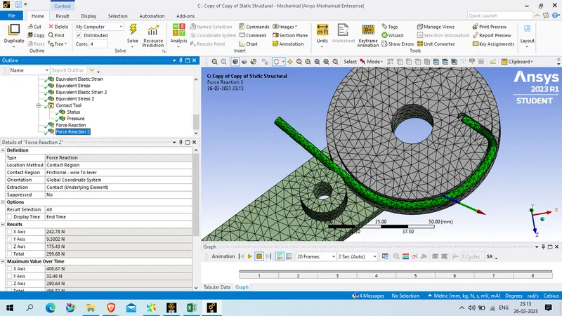
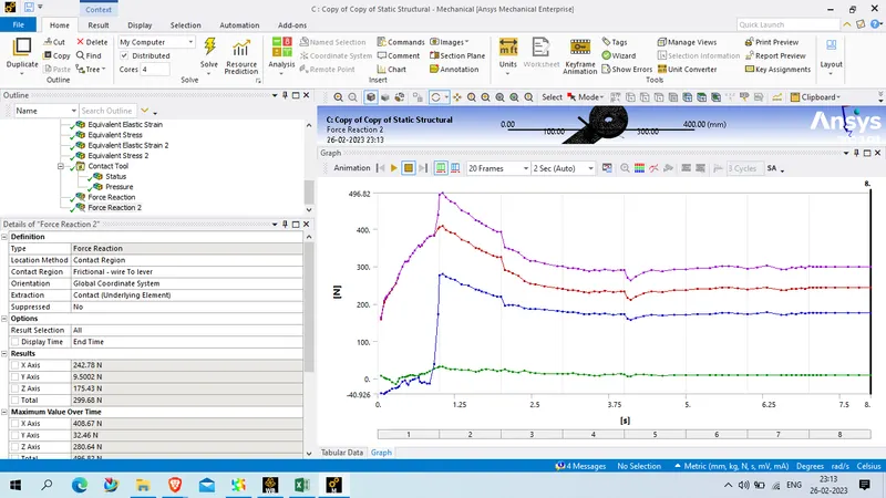
Force reaction at wire to lever
Result :
| Copper | Aluminium | Magnesium | ||
| Total deformation | Max | 262.64 mm | 262.64 mm | 262.64 mm |
| Min | 0. mm | 0 mm | 0. mm | |
| Total elastic strain | Max | 2.95E-03 | 4.54E-03 | 5.85E-03 |
| Min | 3.18E-09 | 3.18E-09 | 3.22E-09 | |
| Equivalent strain on wire | Max | 2.95E-03 | 4.54E-03 | 5.85E-03 |
| Min | 6.58E-08 | 6.70E-08 | 6.89E-08 | |
| Equivalent stress | Max | 323.53 MPa | 321.35 MPa | 262.38 MPa |
| Min | 4.8001e-004 MPa | 4.156e-004 MPa | 4.4752e-004 MPa | |
| Equivalent stress on wire | Max | 323.53 MPa | 321.35 MPa | 262.38 MPa |
| Min | 4.0498e-003 MPa | 2.6043e-003 MPa | 1.6286e-003 MPa | |
| Contact pressure | Max | 456.93 MPa | 207.77 MPa | 258.03 MPa |
| Min | 0. MPa | 0. MPa | 0. MPa | |
| Frictional force reacrion wheel to wire | Total | 660.22 N | 423.65 N | 359.04 N |
| Frictional force reaction wire to lever | Total | 541.21 N | 376.95 N | 299.68 N |
Conclution :
1. Magnesium alloy NL material experiance least stress comprared to all material which is 262.38 MPa, rest two material experiance near about same stress which is 323.53 MPa for copper alloy NL and 321.35 MPa for aluminum alloy NL
2. simillarly Magnesium alloy material feels max strain which is 0.005846 and aluminium alloy have von misses strain of 0.0045417 and least to copper which is 0.0029452