Week 4 -Wire Bending Challenge
Stress Concentration on Wire Bending
OBJECTIVES:
To carry out a Static Structural Analysis on wire for the given three cases which uses different materials for the wire and determine the stress, deformation, and strain.
CASE-1:
For Case-1, Static Structural Analysis was carried out with the given wire model. The material used for this analysis was COPPER ALLOY NL and the analysis was carried out using ANSYS Mechanical Enterprise. The model for case-1 was imported to ANSYS Workbench software and is shown in the figure below.
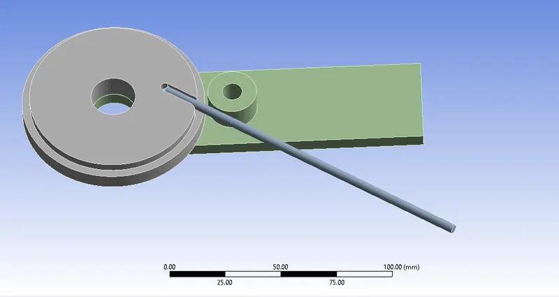
Fig.1 Case-1 Wire Model Setup
Later the material was assigned and the material and its properties used for this analysis are specified below. For Wheel and Lever, STRUCTURAL STEEL was used in all three cases.
|
Material |
Copper Alloy NL |
|
Density |
6.999e-6 kg/mm3 |
|
Young’s Modulus |
1.1e+5 MPa |
|
Thermal Conductivity |
0.06 W/mm°C |
|
Specific Heat |
3.85e+5 mJ/kg°C |
|
Tensile Yield Strength |
79.81 MPa |
|
Tensile Ultimate Strength |
141.4 MPa |
MESHING:
Meshing is done by setting a method using tetrahedron elements. A Face sizing of 2.2mm is set to critical faces on the wire, wheel, and lever. A coordinate system was created on an area around the wire where the wire and wheel have contact and meshing is set using a sphere of influence with a radius of 7mm and element size of 0.8mm.
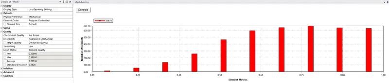
Fig.2 Element Quality
A mesh metric that identifies elements according to their quality was employed and it can be seen that the elements of the lowest quality are minimal. Most of the elements have very high quality in the range of 0.6 to 1. Hence, the mesh is of acceptable quality. The meshed model is shown below.
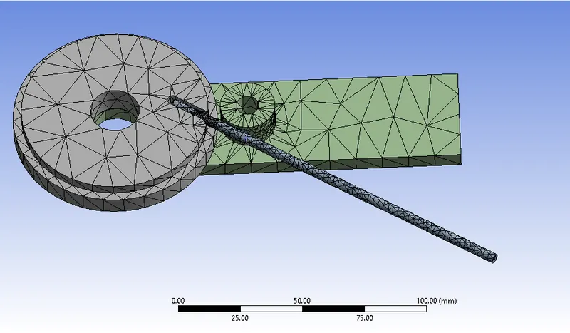
Fig.3 Meshed Model
CONTACT:
The contacts between the wheels and the wire are specified with a frictional type connection. Two contacts are set: a) Wheel (contact), wire (target); b) lever (target), wire (contact). Both contacts have the following data set.
- Friction value of 0.2
- Augmented Lagrange
- Normal Stiffness factor of 0.1
- Update stiffness by each iteration
- Interface treatment of add offset and ramped effect
ANALYSIS SETTING:
8 STEPS ARE USED.
For step 1:
- Auto Time Stepping: On
- Defined by: Time
- Initial time: 0.1s
- Minimum time: 0.01s
- Maximum time: 0.2s
- Solver Type: Direct
- Weak Spring: Controlled
- Large deflection: ON
For steps 2 to 8:
- Auto Time Stepping: On
- Defined by: Time
- Carry on time: ON
- Minimum time: 0.01s
- Maximum time: 1s
- Solver Type: Direct
- Weak Spring: Controlled
- Large deflection: ON
- Output controls: Set all to YES
BOUNDARY CONDITIONS AND LOAD:
The FIXED SUPPORT was provided to the Wheel and Wire to stay in their place and REVOLUTE JOINT on the lever with the ROTATION increasing in order of 20 degrees from 0 to 140 degrees.
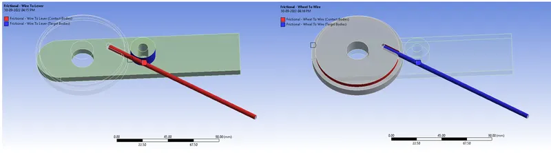
Fig.4 Frictional Contact
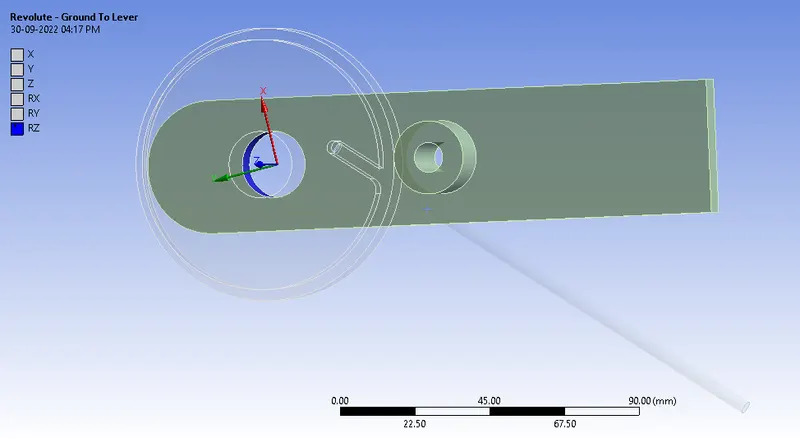
Fig.5 Revolute Joint
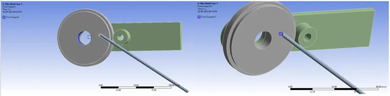
Fig.6 Fixed Supports
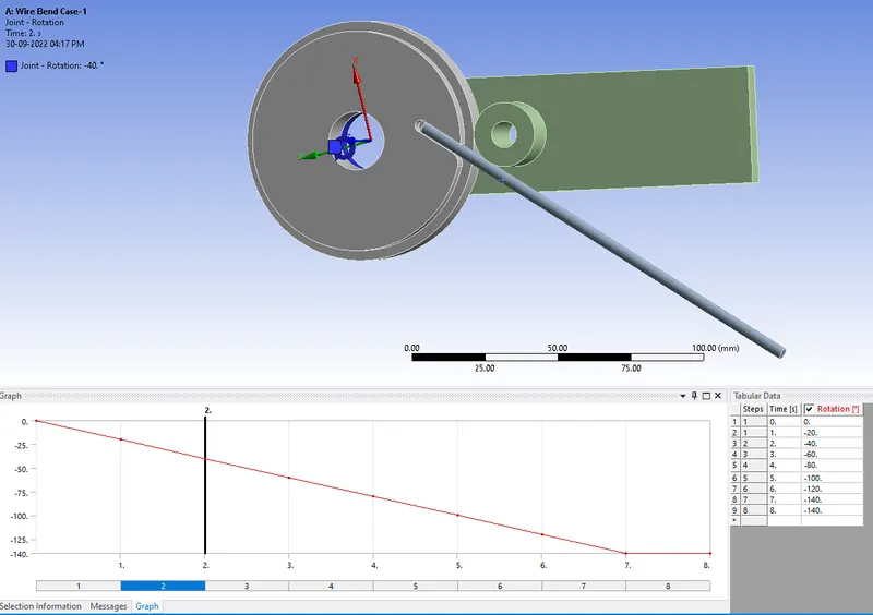
Fig.7 Load Applied
CASE-2:
For Case-2, Static Structural Analysis was carried out with the given spur gear model. The material used for this analysis was ALUMINUM ALLOY NL and the analysis was carried out using ANSYS Mechanical Enterprise. Later the material was assigned and the material and its properties used for this analysis are specified below for both gears.
|
Material |
Aluminum Alloy NL |
|
Density |
2.77e-6 kg/mm3 |
|
Young’s Modulus |
71000 MPa |
|
Thermal Conductivity |
0.06 W/mm°C |
|
Specific Heat |
8.75e+5 mJ/kg°C |
|
Yield Strength |
280 MPa |
|
Tangent Modulus |
500 MPa |
The same contacts and load used in Case-1 were used in Case-2 also with only a change in the Material of the Wire. Then the analysis was run and results were obtained.
CASE-3:
For Case-3, Static Structural Analysis was carried out with the given spur gear model. The material used for this analysis was MAGNESIUM ALLOY NL and the analysis was carried out using ANSYS Mechanical Enterprise. Later the material was assigned and the material and its properties used for this analysis are specified below for both gears.
|
Material |
Magnesium Alloy NL |
|
Density |
1.8e-6 kg/mm3 |
|
Young’s Modulus |
45000 MPa |
|
Thermal Conductivity |
0.06 W/mm°C |
|
Specific Heat |
1.024e+6 mJ/kg°C |
|
Yield Strength |
193 MPa |
|
Tangent Modulus |
920 MPa |
The same contacts and load used in Case-1 were used in Case-3 also with only a change in the Material of the Wire. Then the analysis was run and results were obtained.
RESULTS:
The Total Deformation of the setup was obtained from the analysis and compared below.
|
Case |
Minimum [mm] |
Maximum [mm] |
Average [mm] |
|
1 |
0 |
262.64 |
62.555 |
|
2 |
0 |
262.64 |
62.571 |
|
3 |
0 |
262.64 |
63.582 |
The Equivalent (Von-Mises) Stress in the wire was obtained from the analysis and compared below.
|
Case |
Minimum [MPa] |
Maximum [MPa] |
Average [MPa] |
|
1 |
4.5588e-003 |
339.02 |
144.24 |
|
2 |
2.8065e-3 |
340.19 |
119.47 |
|
3 |
1.7938e-3 |
259.08 |
110.23 |
The Equivalent Elastic Strain in the wire was obtained from the analysis and compared below.
|
Case |
Minimum [MPa] |
Maximum [MPa] |
Average [MPa] |
|
1 |
7.7763e-8 |
3.0984e-3 |
1.6307e-3 |
|
2 |
7.4775e-8 |
4.8333e-3 |
2.1556e-3 |
|
3 |
7.5654e-8 |
6.6198e-3 |
3.0041e-3 |
The Total Deformation for all the three cases obtained from the analysis is shown below.
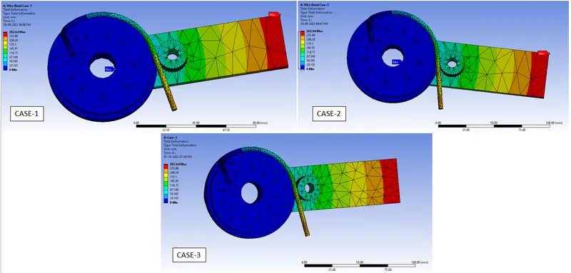
Fig.8 Total Deformation Contour Plot
The Equivalent (Von-Mises) Stress of wire for all three cases obtained from the analysis is shown below.
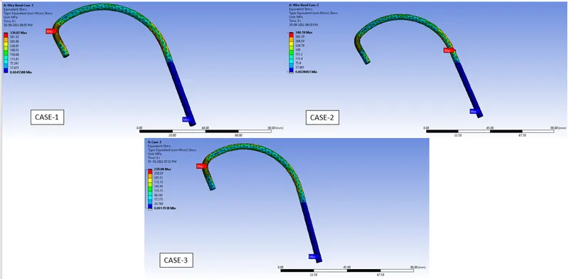
Fig.9 Equivalent Stress Contour Plot
The Equivalent Elastic Strain of Wire for all the three cases obtained from the analysis is shown below
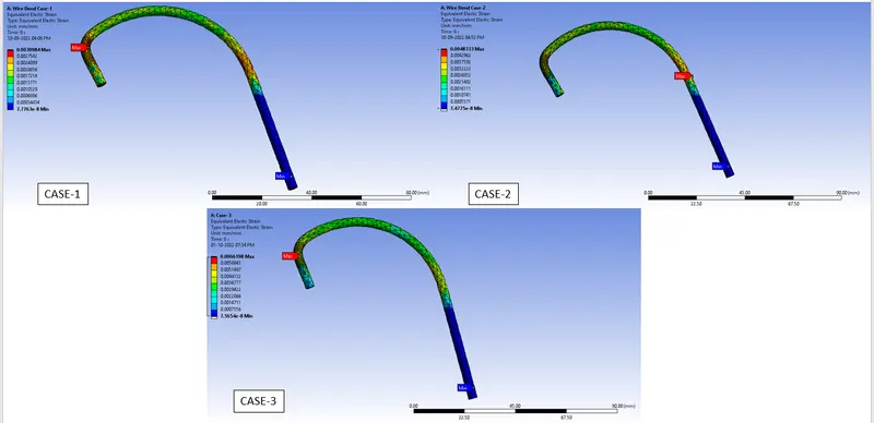
Fig. 10 Equivalent Elastic Strain Contour Plot
The Total Deformation graph/table plot is shown below.
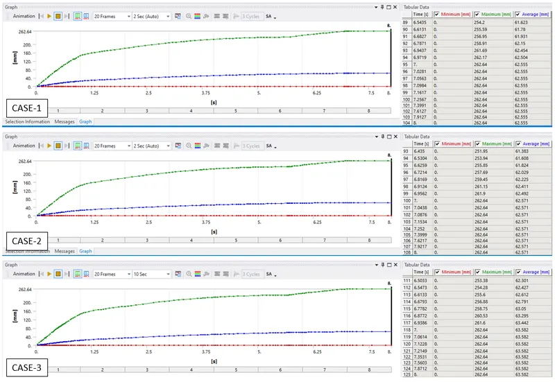
Fig.11 Total Deformation Table Plot
The Equivalent (Von-Mises) Stress graph plot is shown below.
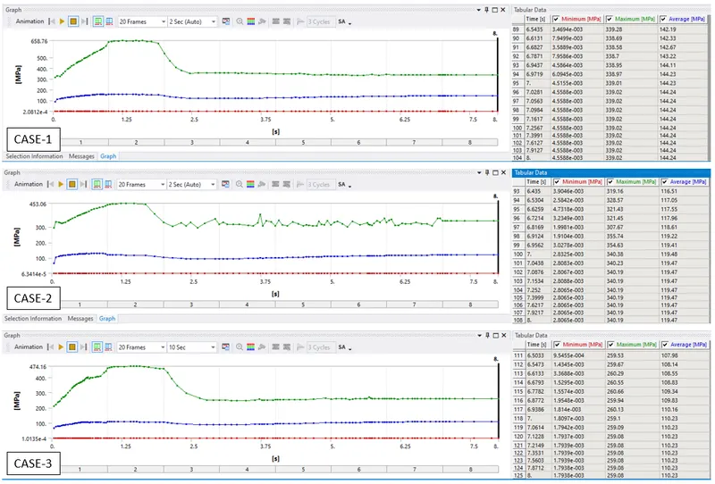
Fig.12 Equivalent Stress Table Plot
The Equivalent Elastic Strain graph plot is shown below
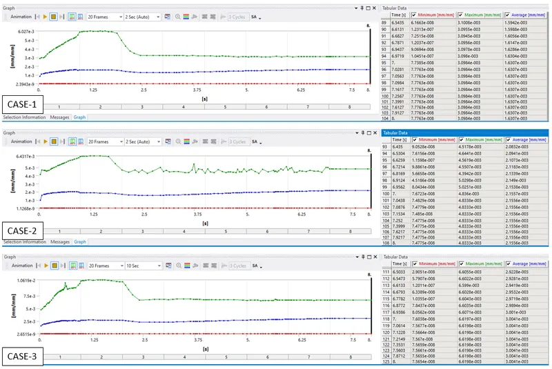
Fig. 13 Equivalent Elastic Strain Table Plot
The Maximum Stress and Strain of the wire from the Tabular Data for three cases are tabulated below
|
Case |
Equivalent Stress Max. [MPa] |
Equivalent Elastic Strain Max. [mm/mm] |
|
1 |
658.76 |
6.0270e-3 |
|
2 |
453.06 |
6.4317e-3 |
|
3 |
474.16 |
1.0619e-2 |
CONCLUSION:
The analysis was run successfully for all three cases and results were obtained and tabulated.
From the comparison table, it is evident that copper alloy wire produces the maximum stress whereas Magnesium alloy undergoes the maximum strain. The young's modulus is different in all cases and it is decreasing. Young's modulus is equal to the ratio of stress to strain. Strain is inversely proportional to young's modulus. Young's modulus is decreasing means strain will be increasing which satisfies the solution.
From the simulation results, we can see that the Case 2 material that is Aluminum Alloy NL has experienced the least Max. Equivalent Stress compared to the other materials Copper Alloy NL and Magnesium Alloy NL. Even though Aluminum Alloy NL has experienced a bit higher Max. Equivalent Elastic Strain than Copper Alloy NL, we can see that the latter has experienced larger Max. Equivalent Stress. So, we can conclude that Aluminum Alloy NL is the better material suited for the Wire Bending process out of the given materials.