Week 4 -Wire Bending Challenge
Bending analysis on wires made up of different materials:
Aim: Performing Bending analysis on wires made up materials of Copper Alloy NL, Aluminium Alloy NL and Magnesium Alloy NL.
Steps followed:
1)Material Selection:
Wires:
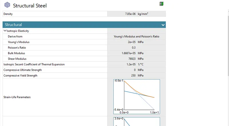
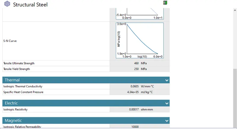
Structural Steel is choosen as material for wheel & lever in all 3 cases with material specifications shown in the image below:
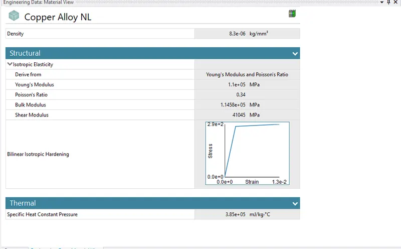
Case 1: Copper Alloy NL is choosen as a material for wire with the specifications given in the image below:
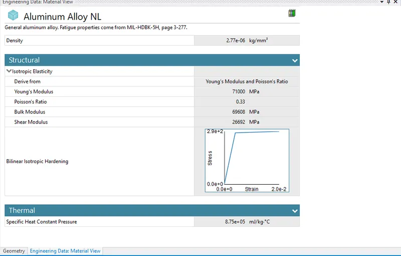
Case 2: Aluminium Alloy NL is choosen as a material for wire with the specifications given in the image below:
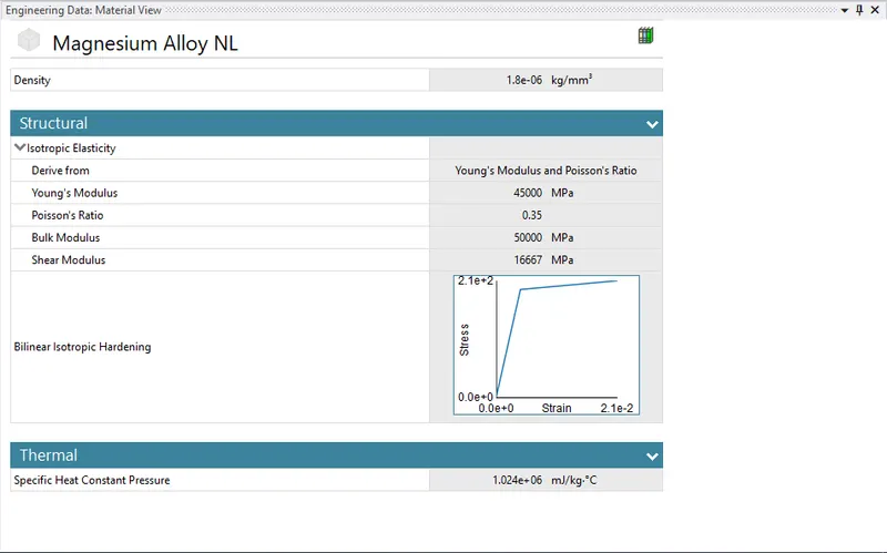
Case 3: Magnesium Alloy NL is choosen as a material for wire with the specifications given in the image below:
2)Geometry:
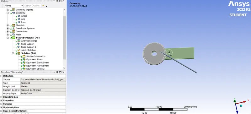
The required model of Wheel,Lever and wire assembly is imported from CAD file. Parts of geometry are renamed as Wheel,Wire and Lever as shown in the image below with Structural Steel material assingnment for wheel & lever:
3)Contacts:
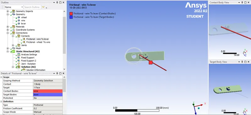
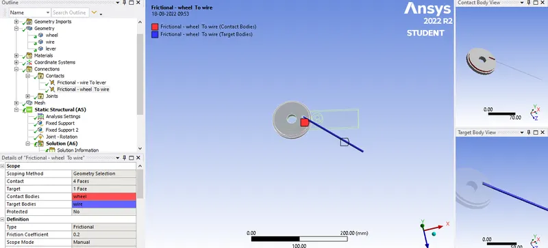
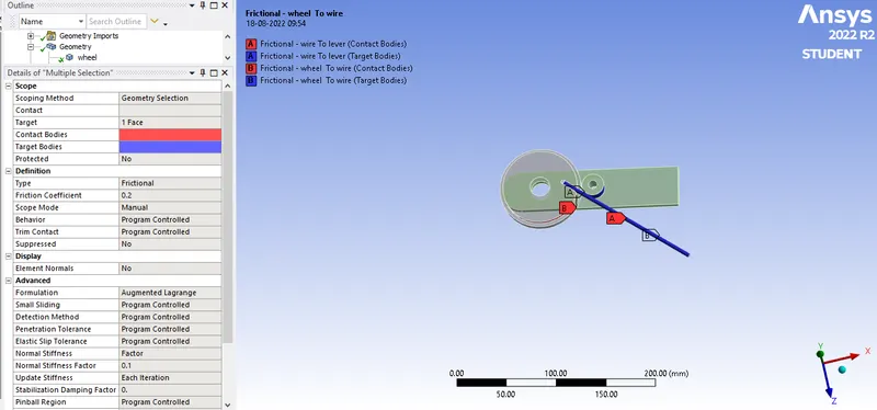
After selecting Contacts from the Connections we create Frictional contact between Wire & Lever and wire wheel by selecting their faces as shown in the image below with frictional coefficient of 0.2 and Formulation selected as Augumented Lagrange. Normal stiffness is selected as factor with Normal Stiffness factor as 0.1 & Update Stiffness as Each Iteration with Interface Treatmen as Add Offset, Ramped effects.
For all the 3 cases Contacts & its settings are similar.
Contacts between Wire & Lever with Contact as wire & Target as lever:
Contacts between Wire & Wheel with Contact as wire & Target as wheel:
Contact Settings:
4)Joints:
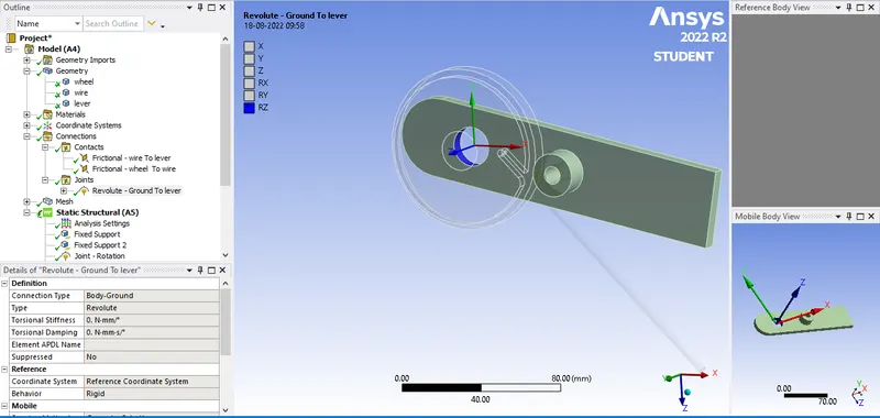
For all the 3 cases Joints & its settings are similar.
A Body-Ground Connection type Revolute joint is applied by selecting on of the faces of lever such that rotation is possible about Z axis as shown in the image below:
5)Meshing:
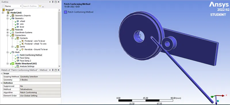
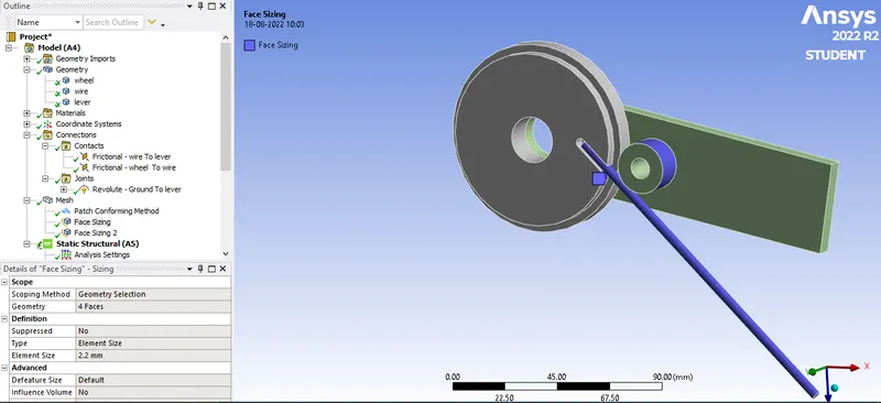
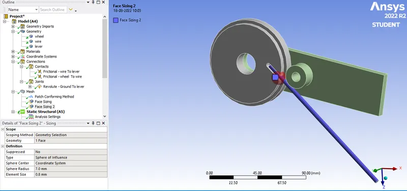
Meshing is given with high quality Smoothing by selecting Tetrahedron elements with Face sizing of 2.2mm at the contact face wire & lever with wire. Another face sizing of 0.8 mm with Sphere of influence type and Sphere radius as 7mm is applied at the curve face of wheel at wire entry. For all the 3 cases meshing are similar.
Tetrahedron Elements are selected as shown in the image below:
Face sizing of 2.2 mm at wire & lever:
Face sizing with sphere of influence type at the curve face of wheel:
6)Boundary canditions:
a)Analysis Settings:
Number of steps taken for analysis is 8 with Auto time stepping On with Intial time step as 0.1s,Minimum time step as 0.01s and Maximum time step as 0.2s. Solver type selected as Direct & Large deflections On with all Output Controls selected as yes:
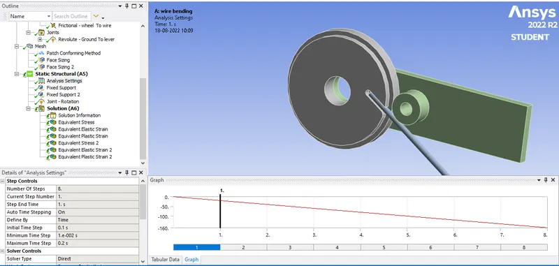
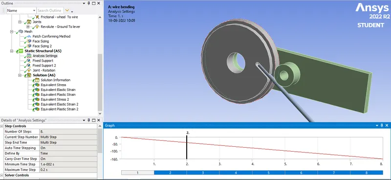
For steps 2 to 8 Carry Over time step as On,Minimum time step as 0.01s and Maximum time step as 0.2s.
b)Fixed support:
A fixed support is applied at the face of wheel as shown in the image below:
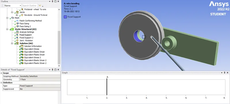
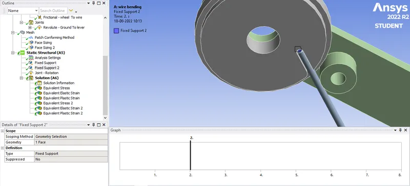
Another fixed support is applied to the face at the end of wire in contact with wheel as shown in the image below:
c)Joint-Rotation:
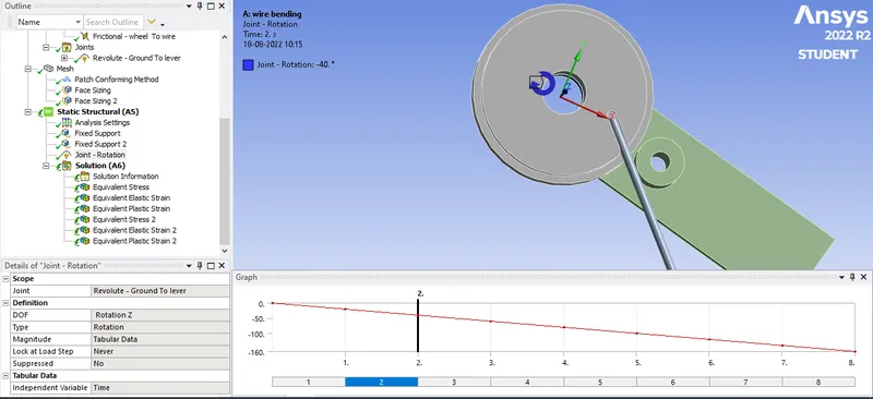
A rotation is applied at the revoulte joint of lever in tabular format along -ve Z axis as shown in the image below:
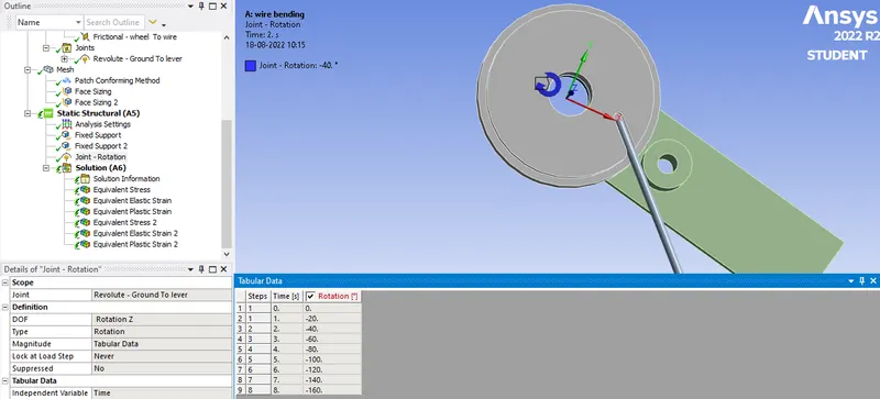
Tabular data for input rotation is shown in the image below:
Results:
Case 1: Wire is made up Copper Alloy NL
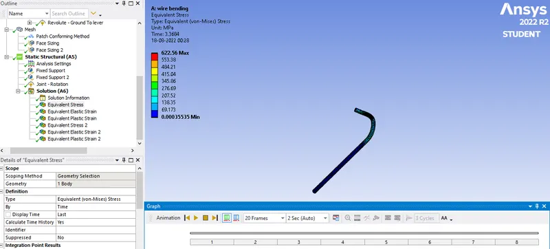
Equivalent Stress:
Equivalent Stress vs Time graph:
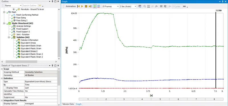
Maximum Equivalent stress:622.56 MPa
Equivalent Elastic Strain:
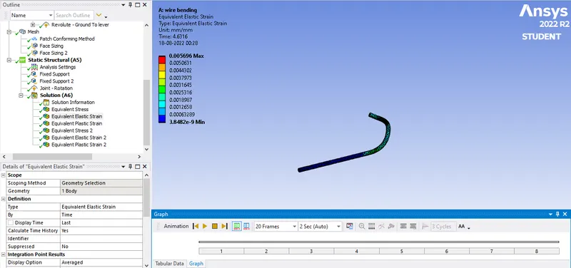
Equivalent Elastic Strain vs Time graph:
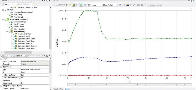
Maximum equivalent elastic strain:0.005696
Equivalent Plastic strain:
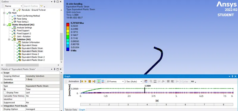
Equivalent plastic strain vs Time:
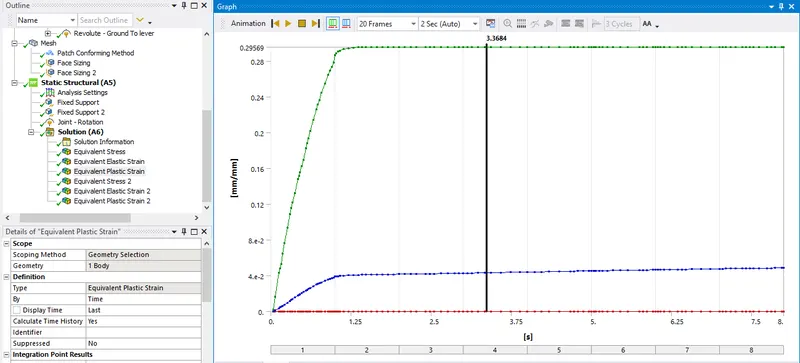
Maximum Equivalent plastic strain:0.29569
Case 2: Aluminium Alloy NL material is selected for analysis.
Equivalent Stress:
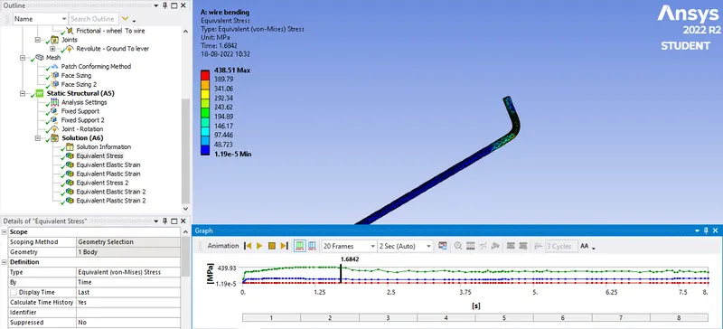
Equivalent Stress vs Time graph:
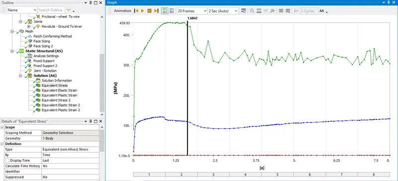
Maximum Equivalent stress:439.93 MPa
Equivalent Elastic Strain:
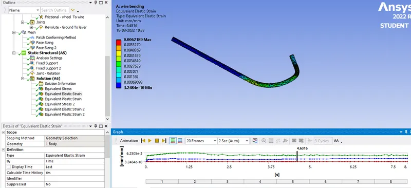
Equivalent Elastic Strain vs Time graph:
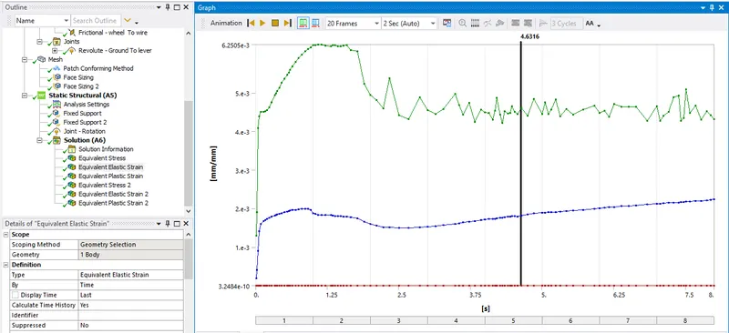
Maximum equivalent elastic strain:0.0062189
Equivalent Plastic strain:
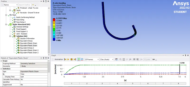
Equivalent plastic strain vs Time:
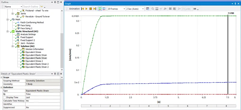
Maximum Equivalent plastic strain:0.31951
Case 3: Magnesium Alloy NL is selected as a material for wire.
Equivalent Stress:
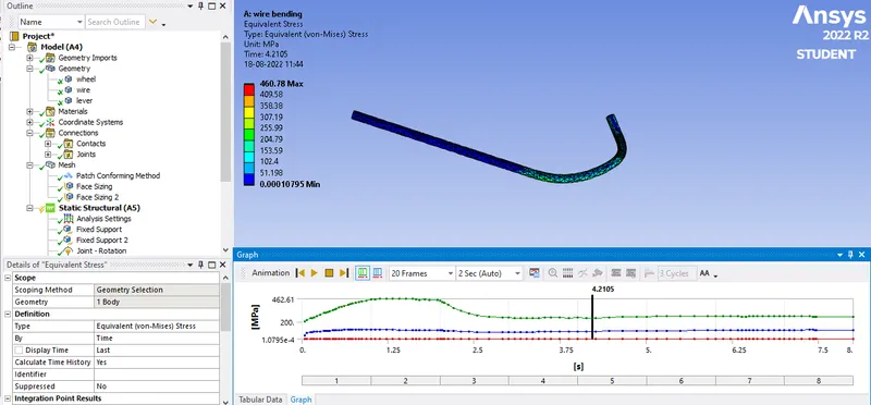
Equivalent Stress vs Time graph:
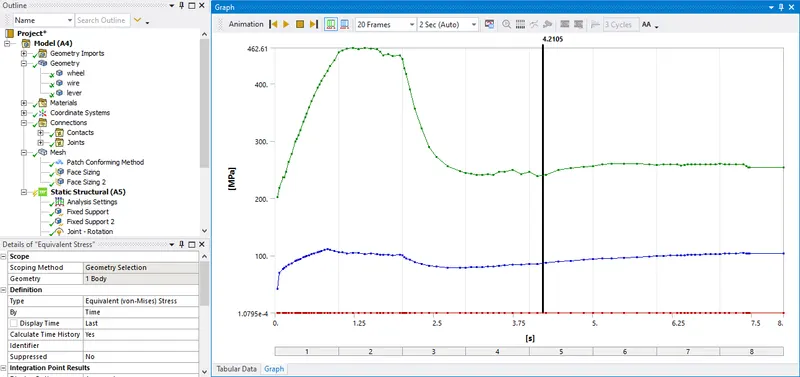
Maximum Equivalent stress:460.78 MPa
Equivalent Elastic Strain:
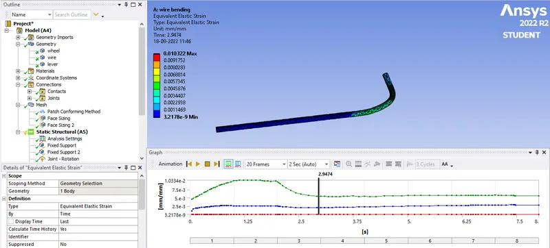
Equivalent Elastic Strain vs Time graph:
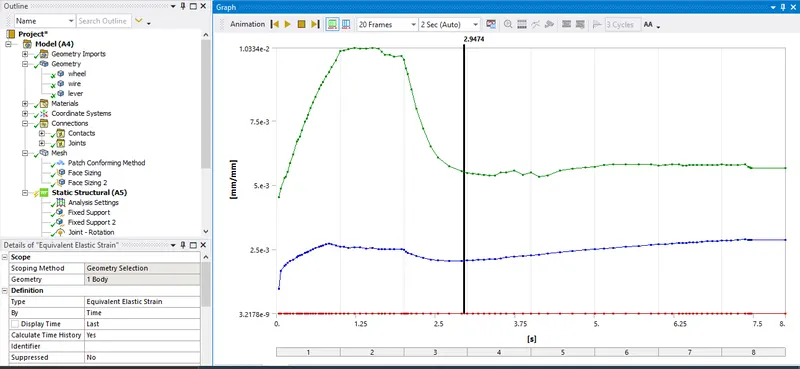
Maximum equivalent elastic strain:0.010322
Equivalent Plastic strain:
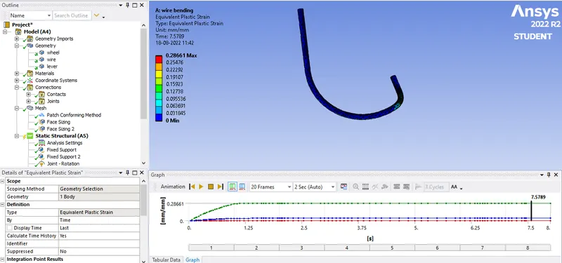
Equivalent plastic strain vs Time:
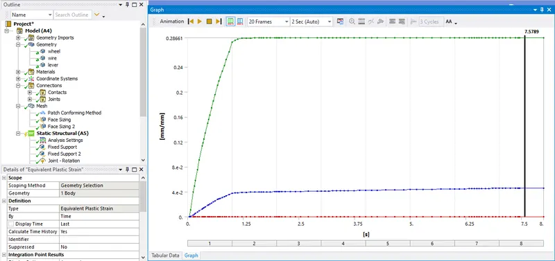
Maximum Equivalent plastic strain:0.28661
Comparision:
Comparision of max equivalent stress,equivalent elastic strain & equivalent plastic strain for wire in case 1,2 & 3:
| Case | Maximum Equivalent Stress(MPa) | Maximum Equivalent Elastic Strain | Maximum Equivalent Plastic Strain |
| 1 | 622.56 | 0.005696 | 0.29569 |
| 2 | 439.93 | 0.0062189 | 0.31951 |
| 3 | 460.78 | 0.010322 | 0.28661 |
Conclusion:
- Least Maximum Equivalent Elastic strain occurs for wire of material Copper NL which has highest Young's modulus compared to Aluminium Alloy NL & Magnesium Alloy NL.
- Highest maximum equivalent stress occurs for wire made up of Copper NL, again due to Young's modulus.
- Maximum equivalent plastic strain occurs for Aluminum alloy NL as seen from the table above.