Week 4 -Wire Bending Challenge
Aim:
To perform an analysis to simulate the bending of a wire in ANSYS.The Copper Alloy (Non Linear), Aluminium Alloy (Non-Linear), and Magnesium Alloy (Non-Linear) are the materials used for the wire alone. To find out the Equivalent stress and Equivalent strain on the wire alone and compare the results.
Case setup and Execution:
CAD model:
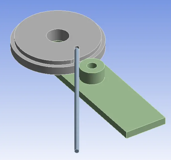
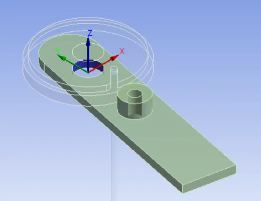
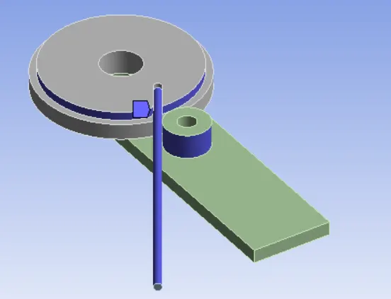
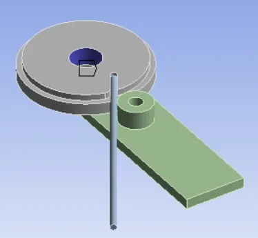
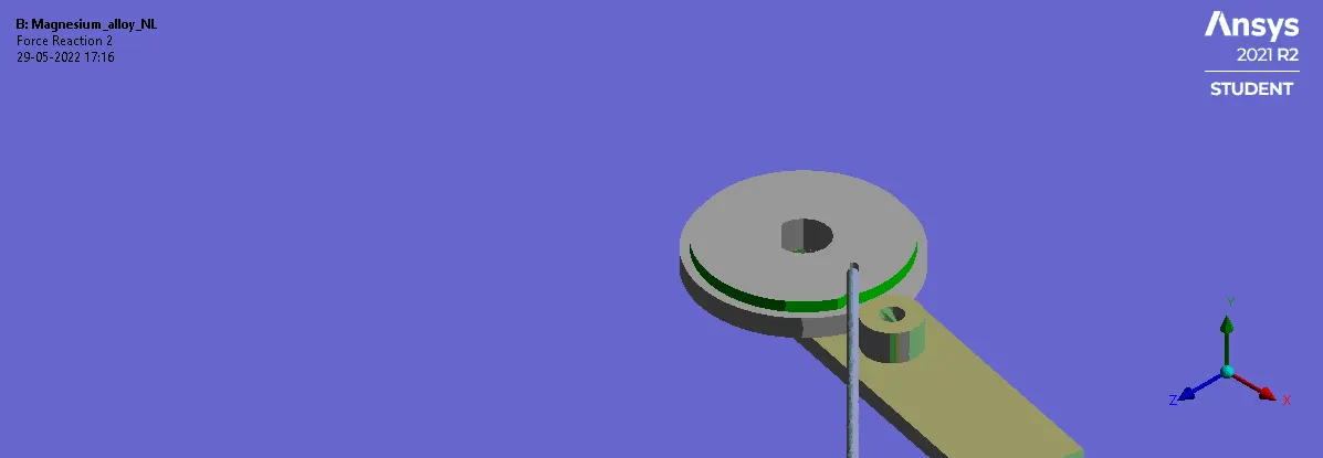
The parts are wheel, wire, lever.
The material properties are:
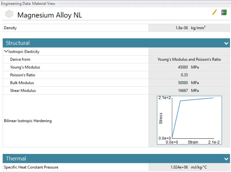
Magnesium alloy non-linear
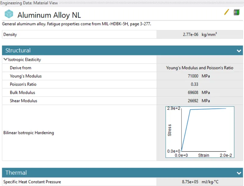
Aluminum alloy non-linear
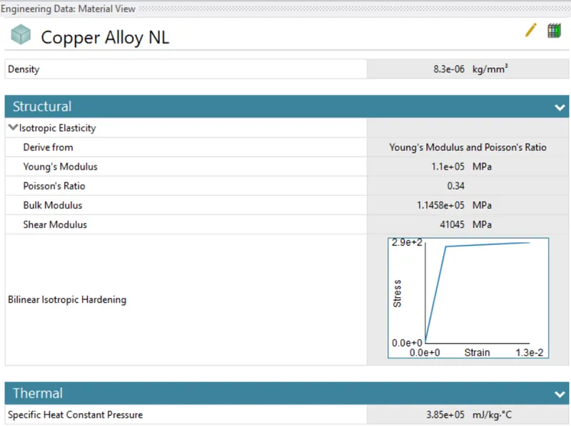
Copper alloy non-linear
Contacts:
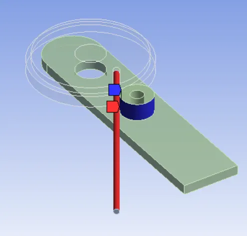
The 2 contacts are defined, one between the lever and wire, and one between wire and the wheel.
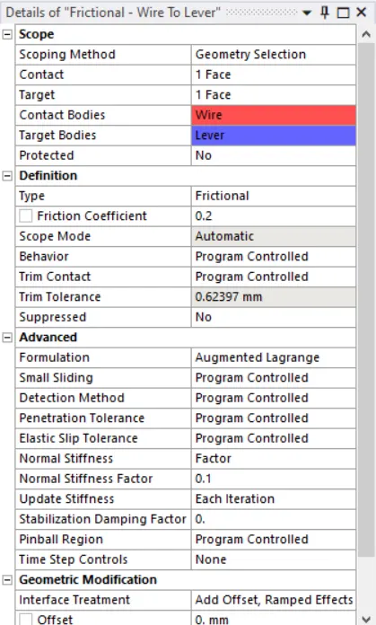
Wire is defined as the contact body and lever is defined as a target body.
The type of contact defined is frinctional with co-efficient of 0.2.
The Augumented lagrange formulation is used.
The normal stiffness is enabled to factor of 0.1.
Update the stiffness for each iteration.
Enable the interface treatment to add offset, ramped effects.
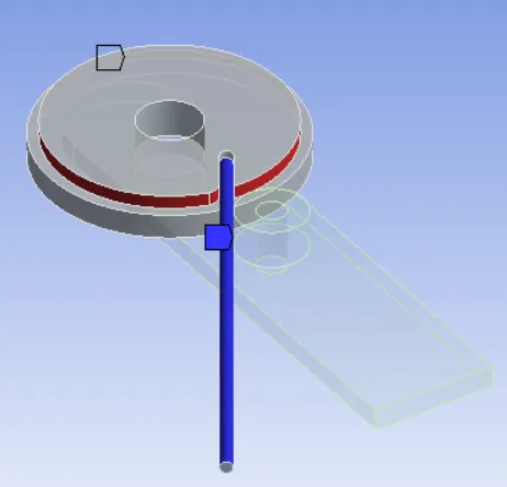
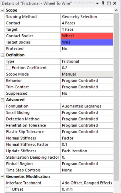
Wheel is defined as the contact body and wire is defined as a target body.
Select the faces which are going to be in contact during the interface between wheel and the wire.
The type of contact defined is frinctional with co-efficient of 0.2.
The Augumented lagrange formulation is used.
The normal stiffness is enabled to factor of 0.1.
Update the stiffness for each iteration.
Enable the interface treatment to add offset, ramped effects.
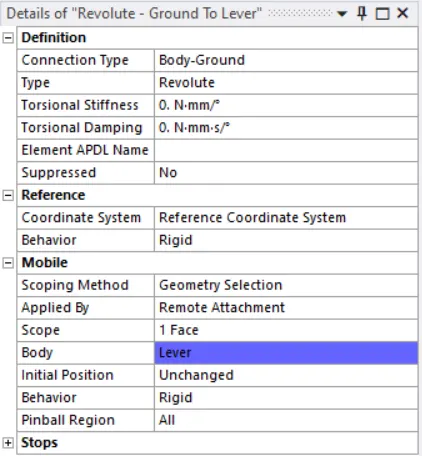
Revolute joint is to be defined w.r.t ground.
Meshing:
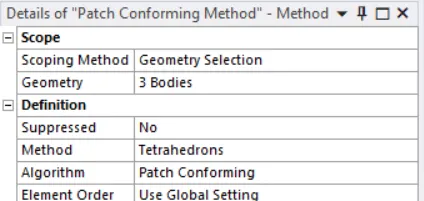
Meshing method is used to mesh the model with tetrahedrons.
The sizing method is used to get finer mesh on the contact parts, to get accurate results on the deformed locations.
The mesh size of 2.2mm is used
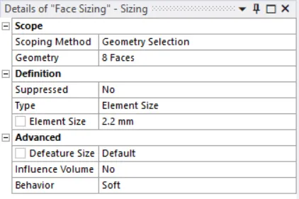
Pinball radius is used to further finer the mesh in the vicinity of the sphere radius.
A co-ordinate system is to be created near the vicinity of where finer mesh is to be created.
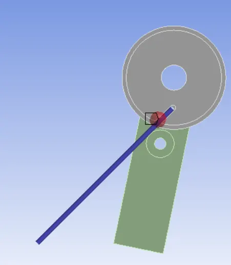
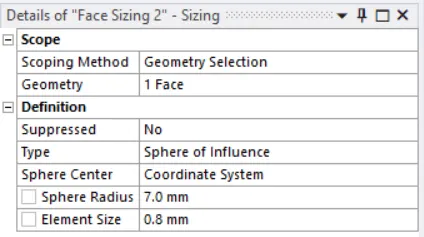
By choosing the sizing with type as sphere of influence and sphere center as co-ordinate system.
Sphere radius as 7mm.
Element size as 0.8mm
Analysis Settings:
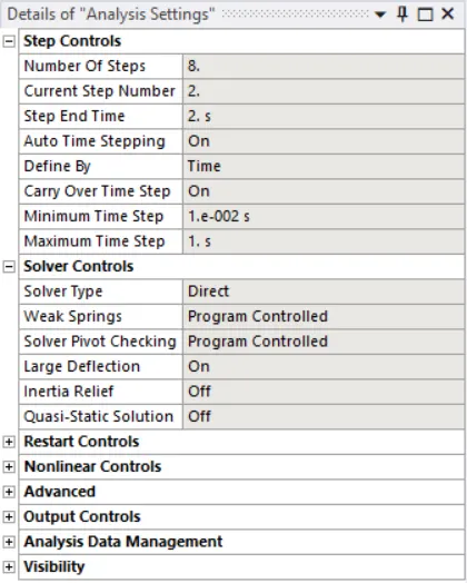
Number of steps used in the simulation is 8.
In the first step, enable Auto time stepping and define by time.
Use initial time step as 0.1s. Minimum time step as 1 e-2 s, Maximum time step as 0.2s.
The solver type is used as direct and large deflection is enabled.
All the parameters in Output controla are enabled.

Cary on timestep is enabled in the further steps with same parameters as first step.
Constraints and motion:
the wheel is fixed using fixed joint.
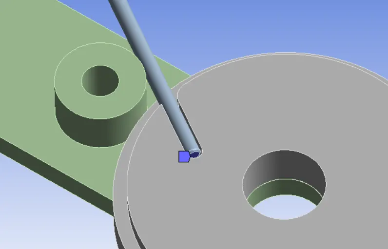
To constrain the wire to move out of the wheel, inner end face is constrained in all directions.
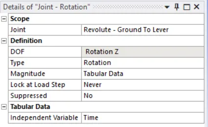
The joint load is provided to the lever w.r.t ground.
The rotation is about the z - axis.
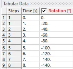
The tabular data shows how rotation of lever takes place at the each step.
The necessary outputs are requested.
Results:
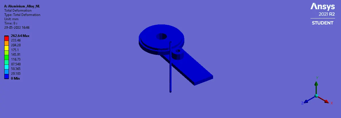
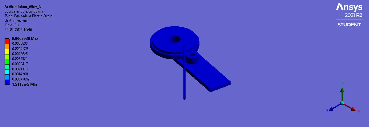
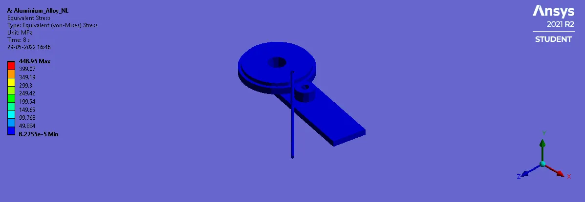
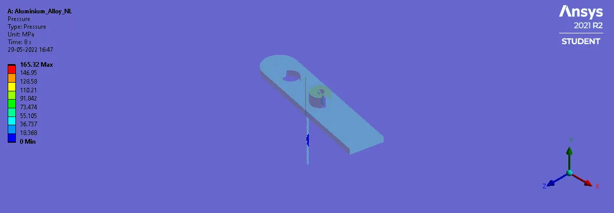
Rod material as Aluminium alloy non-linear:
Total Deformation:
Equivalent elastic strain:
Von-Mises Stress:
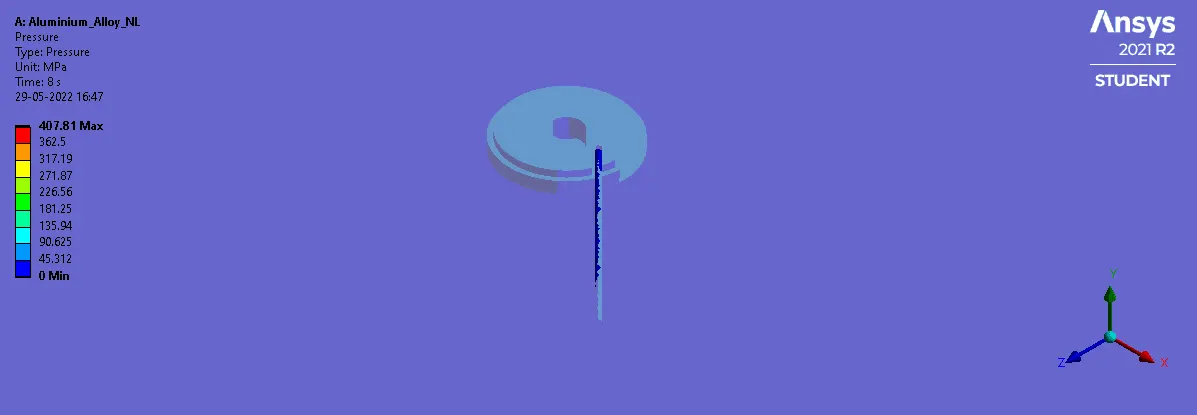
Pressure during the lever and wire contact:
Pressure during the wheel and the wire contact:
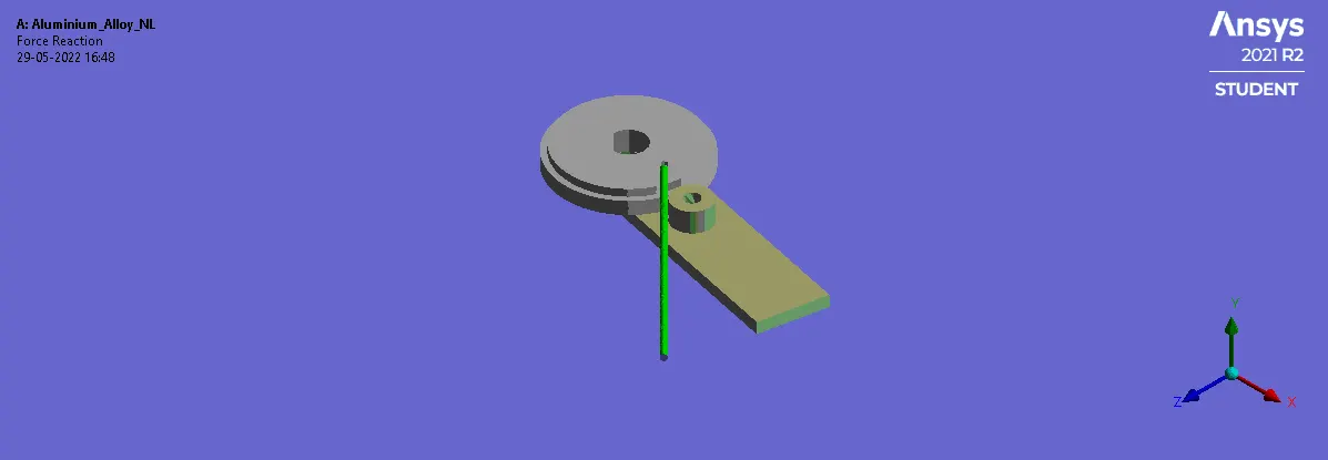
Force reaction during the lever and wire contact:
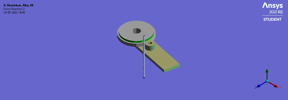
Force reaction during the wheel and wire contact:
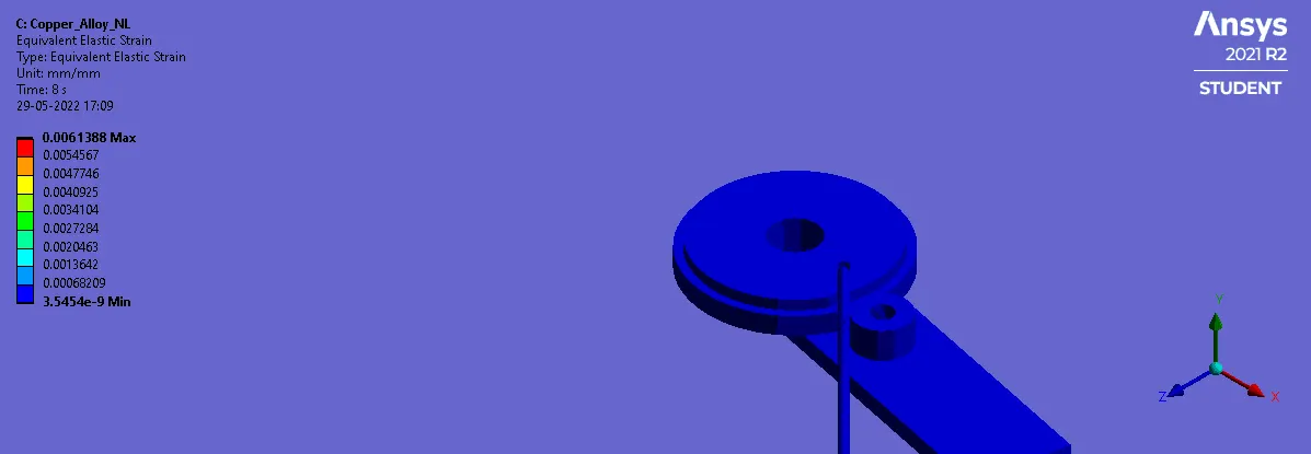
Rod material as copper alloy non-linear:
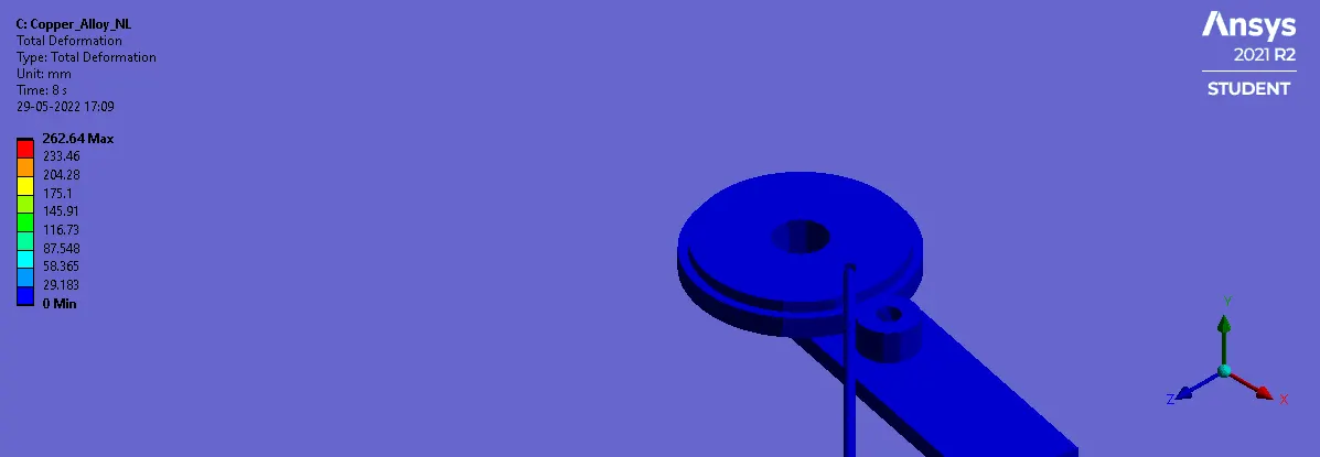
Total Deformation:
Equivalent elastic strain:
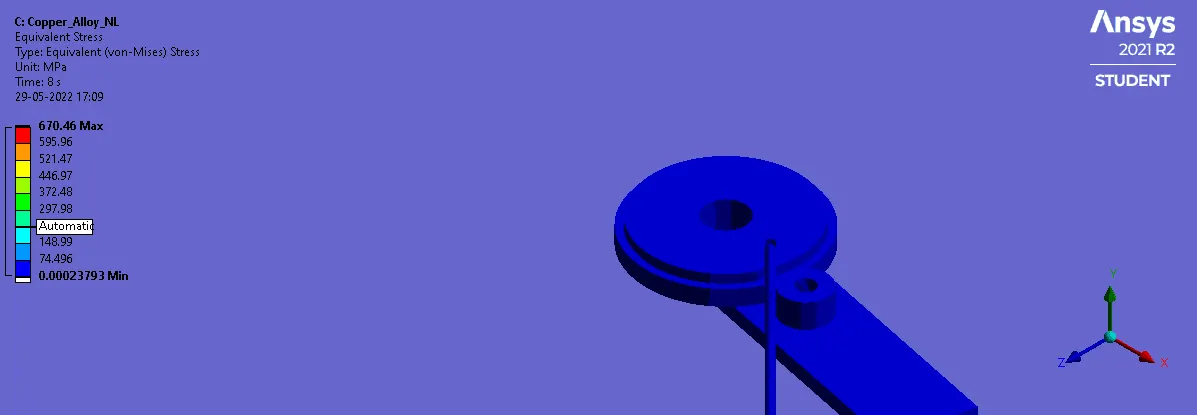
Von-Mises Stress:
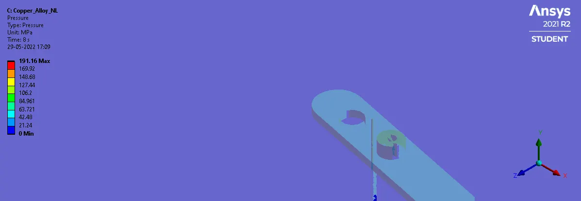
Pressure during the lever and wire contact:
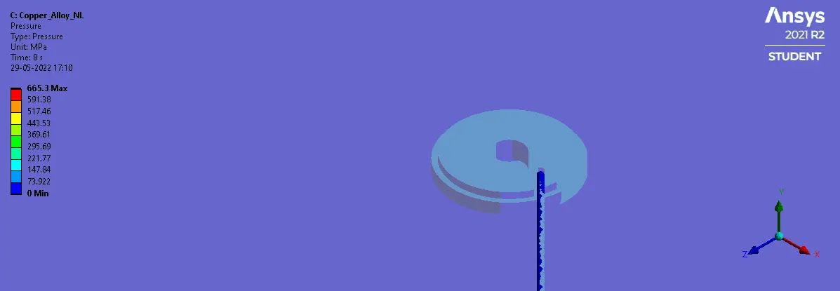
Pressure during the wheel and the wire contact:
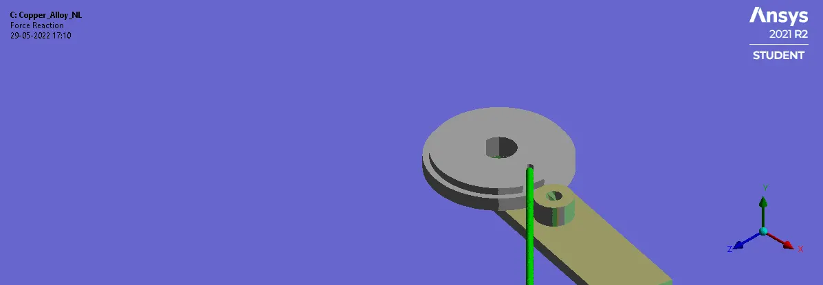
Force reaction during the lever and wire contact:
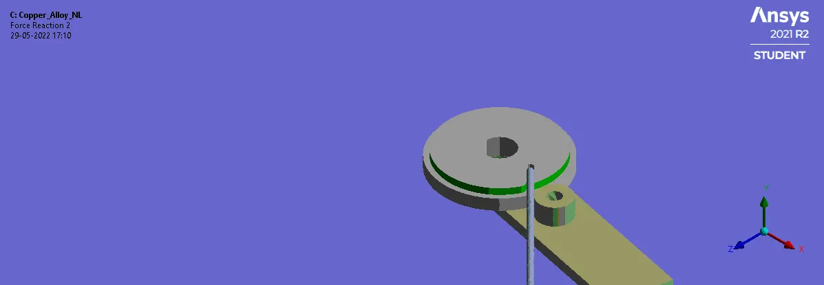
Force reaction during the wheel and wire contact:
Rod material as magnesium alloy non-linear:
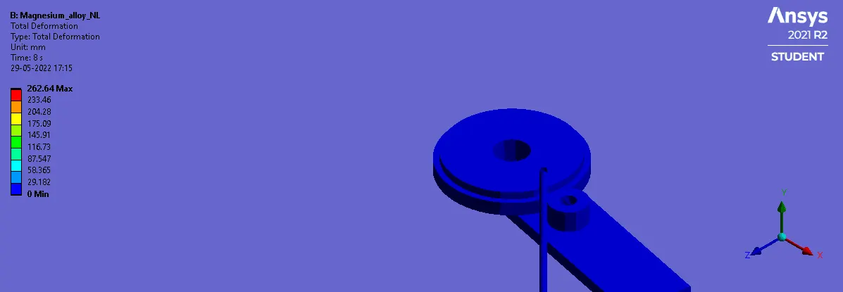
Total Deformation:
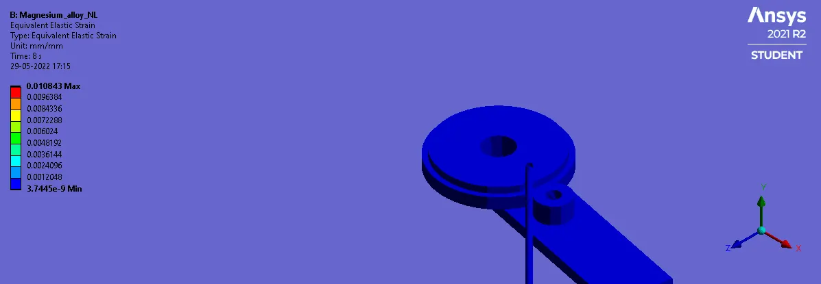
Equivalent elastic strain:
Von-Mises Stress:
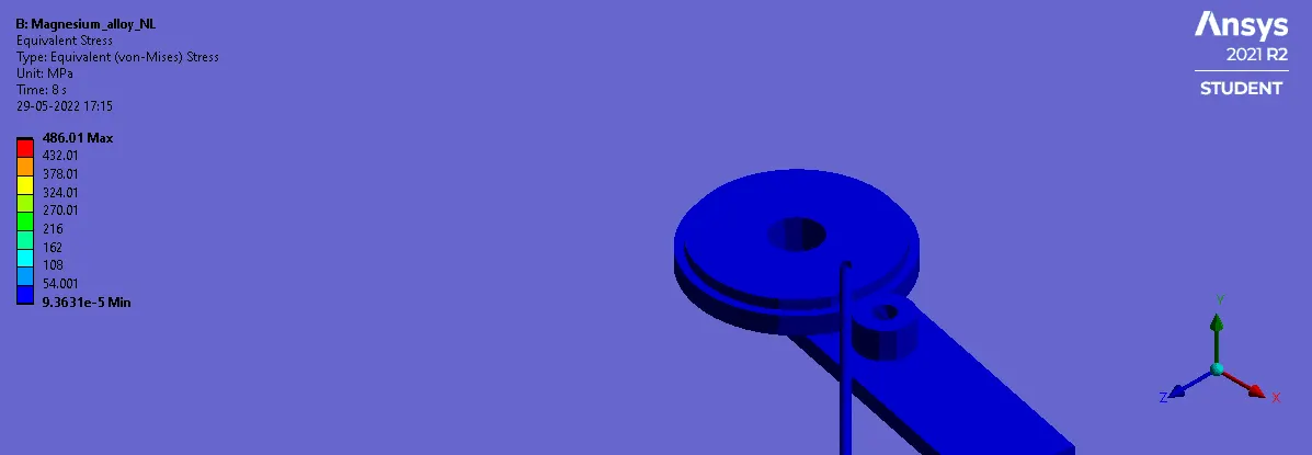
Pressure during the lever and wire contact:
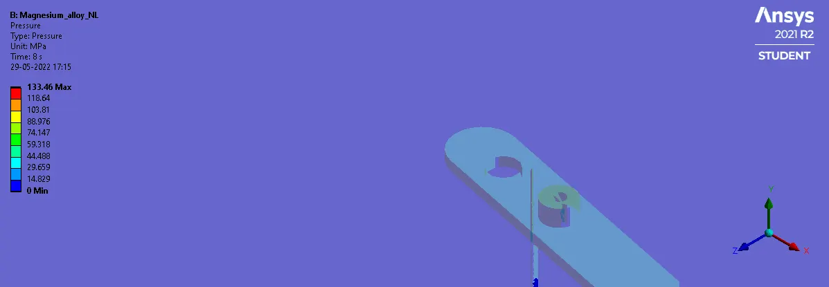
Pressure during the wheel and the wire contact:
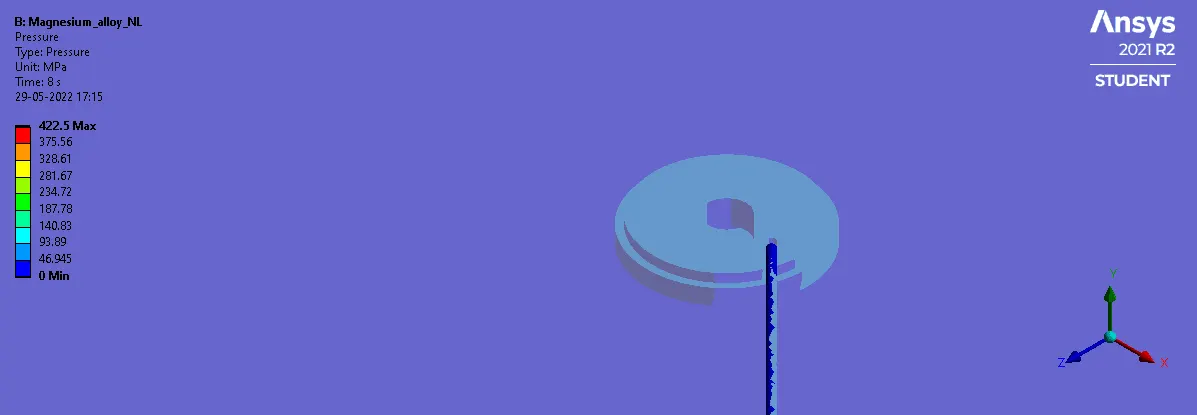
Force reaction during the lever and wire contact:
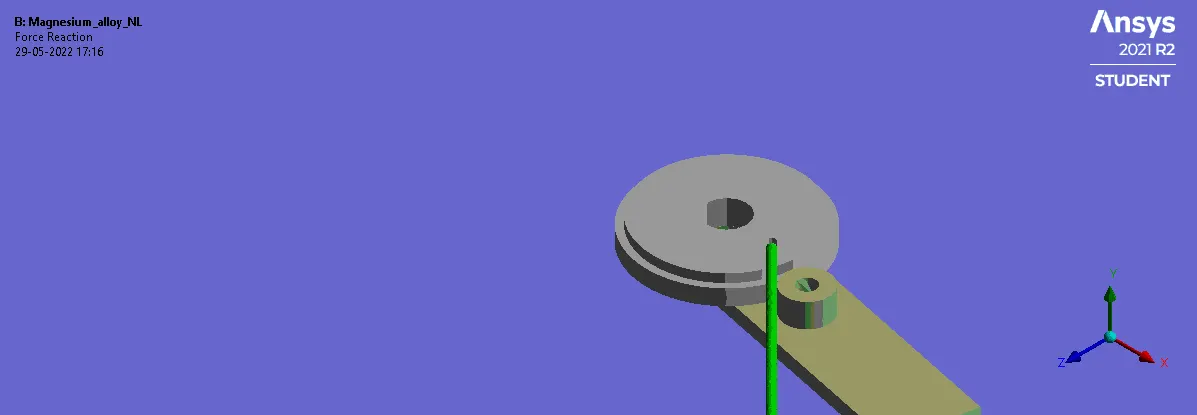
Force reaction during the wheel and wire contact:
Comparison:
The stress and the strain on the wire alone is compared.

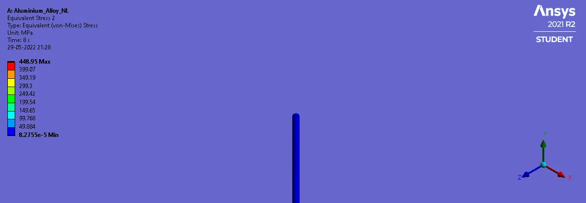
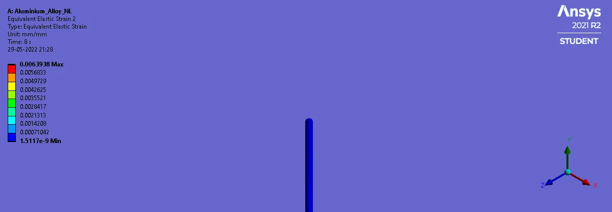
Material as aluminum alloy:
Von-mises stress:
Equivalent strain:
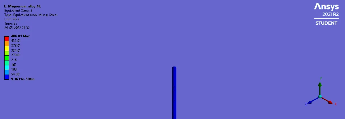
Material as magnesium alloy:
Von-mises stress:
Equivalent strain:
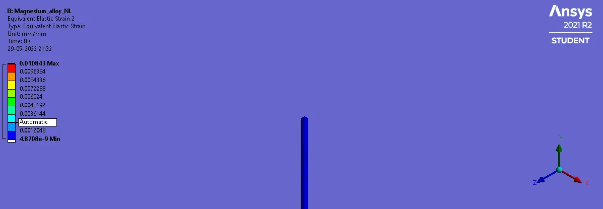
Material as magnesium alloy:
Von-mises stress:
Equivalent strain:
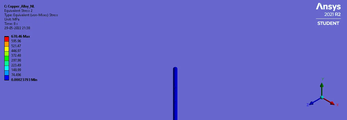
Material as Copper alloy:
Von-mises stress:
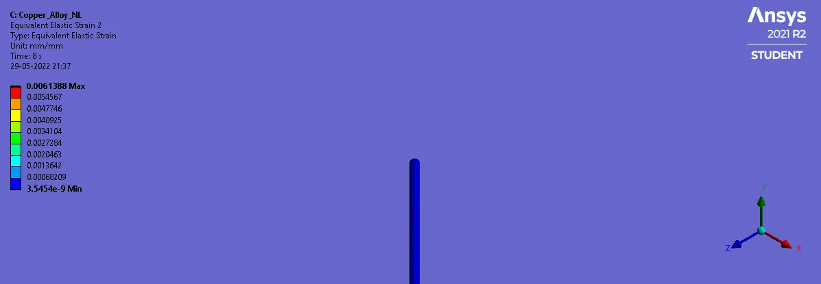
Equivalent strain:
Conclusion:
By looking at the results, we can see aluminium alloy is the material with less maximum strain and less stress on the wire with the same load. Copper alloy is showing the highest stress in the wire which is not feasible even with good strain values. magnesium alloy is showing more strain in the wire, when compared to other with comparable stress values.
By performing the sample tests, we can see the values of stress and strain i.e., to be induced in the wire. With the properties available we can simualte and check if failures occurs or not.
We can get to know what locations are prone to maximum stress and strain.
Overall, Simulation results can conclude if particular material can be used or not to bend into the structures.