Week 4- Rolling operation
ROLLING OPERATION
OBJECTIVE
To simulate rolling of copper workpiece using Ansys-Workbench by readjusting the dimensions of imported geometry and to find equivalent von mises stress, equivalent plastic strain, directional deformation in Z direction and lastly to prove the end of workpiece has been displaced by 90 mm.
METHODOLOGY
The geometry with two rollers and workpiece was imported and checked in Spaceclaim. The length of the workpiece was increased by 60 mm and width of the workpiece was reduced by 8 mm from both sides. The modified body was rechecked for abnormalities in spaceclaim and verified that the geometry was free of abnormalities. Copper alloy NL from ‘General nonlinear materials’ in Engineering data sources was assigned for the sheet material. The material properties of Copper alloy NL are provided in Fig. 1. Structural steel was assigned by default to the rollers. The material properties of Structural steel are given in Fig. 2. Frictional contacts were provided by selecting the outer surface of rollers as target bodies and corresponding contacting surface on the sheets as contact bodies. Figure 3 and figure 4 show the defined contact conditions for the analysis. In the contact settings, frictional contact with coefficient of friction as 0.2, formulation as Augmented Lagrange, normal stiffness factor of 0.1, updating stiffness by each iteration, interface treatment as ‘Add offset, Ramped Effects’ were selected for both contacts. Since the rollers are rotating and causing the sheet to move, cylindrical joint having two degree of freedom namely rotational and translational were assigned for the two rollers. A body to ground and appropriate inner faces of wheels are selected for defining the cylindrical joints. Sheet model meshing with body mesh size of 2 mm are performed. Figure 5 shows the meshed model. The analysis comprises of 14 steps. Large deflection was turned on and stabilization was kept constant with energy dissipation ratio of 0.1. Displacement was provided as constraint to the two faces of workpiece subjected to rolling operation to move in Y direction by 90 mm using intermittent displacements. The rotational degree upto 195° was provided to the rollers using joint load option. Wheel 1 moves in clockwise direction whereas wheel 2 moves in anticlockwise direction. The displacement and rotational degree are provided in Table 1. Finally, von mises equivalent stress, equivalent plastic strain and directional deformation in Z direction are evaluated.
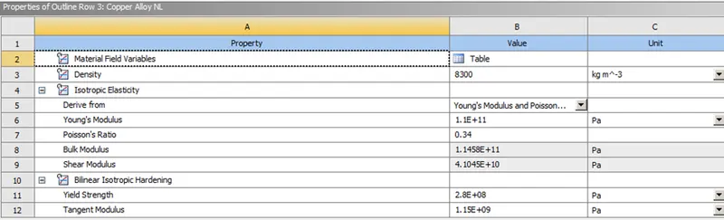
Fig. 1 Material properties of Copper alloy NL
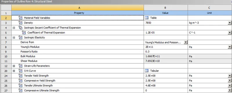
Fig. 2 Material properties of Structural steel
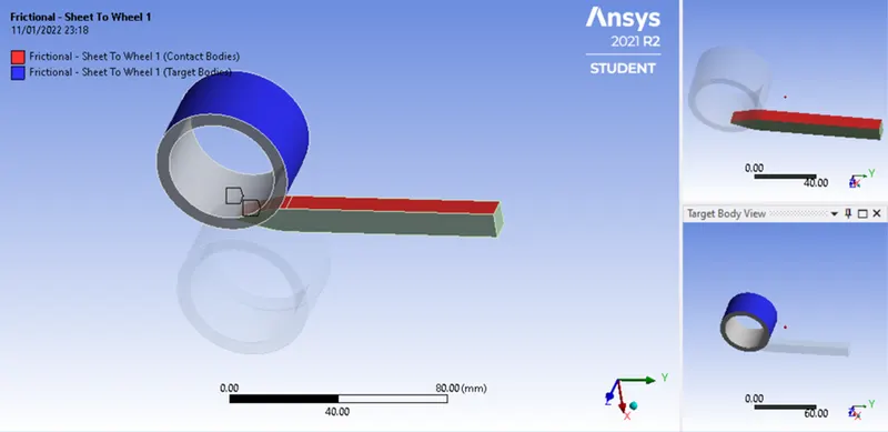
Fig. 3 Frictional contact of sheet to the wheel 1
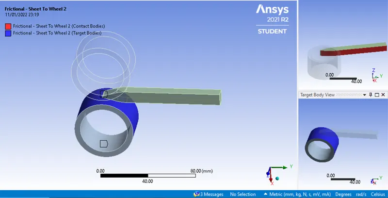
Fig. 4 Frictional contact of sheet to the wheel 2
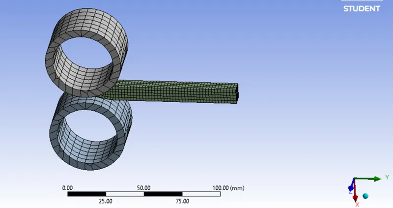
Fig. 5 Meshed model
|
Table 1 Displacement and rotational degree |
|||
|
Steps |
Displacement in Y direction |
Rotational degree - Wheel 1 |
Rotational degree - Wheel 2 |
|
0 1 2 3 4 5 6 7 8 9 10 11 12 13 14 |
0. -3. -6.5 -13. -19.5 -26. -32.5 -39. -42.5 -52. -58. -65. -71.5 -78. -90. |
0. 7. 15. 30. 45. 60. 75. 90. 105. 120. 135. 150. 165. 180. 195. |
0. 7. 15. 30. 45. 60. 75. 90. 105. 120. 135. 150. 165. 180. 195. |
RESULTS AND DISCUSSION
The rolling operation was performed and copper material was rolled down with reduction in the thickness. The material has undergone plastic deformation due to the force exerted by the rollers. As a result of rolling action, the thickness was reduced and the width of the material was increased in Z direction. Due to plastic deformation, von mises equivalent stress of 3486.5 MPa was built up in the material. Equivalent plastic strain of 2.116 has been observed. Maximum directional deformation in Z direction was 8.0683 mm. However, the directional deformation in Z direction was 7.1573 mm at the end time. The results are tabulated in Table 2. Figure 6, figure 7 and figure 8 show the von mises equivalent stress, equivalent plastic strain and directional deformation along Z direction.
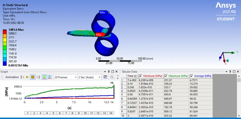
Fig. 6 Equivalent von mises stress
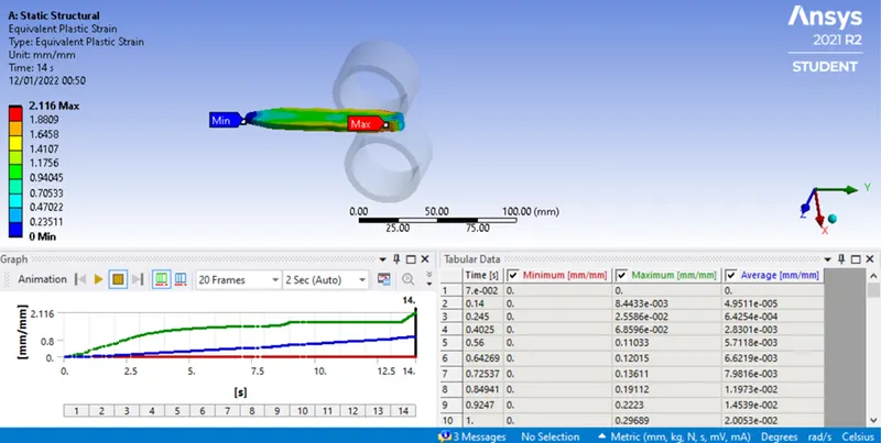
Fig. 7 Equivalent plastic strain
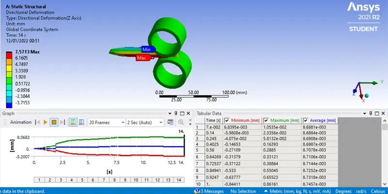
Fig.8 Directional deformation along Z direction
|
Table 2 Results such as Equivalent stress, equivalent plastic strain and directional deformation |
|
|
Material |
Results |
|
Von Mises stress (MPa)- End time |
3485.6 |
|
Maximum Von Mises stress (MPa) |
3485.6 |
|
Equivalent plastic strain- End time |
2.116 |
|
Maximum equivalent plastic strain |
2.116 |
|
Directional deformation (Z direction)(mm) - End time |
7.1573 |
|
Maximum directional deformation (Z direction) (mm) |
8.0683 |
To prove, the workpiece has been displaced by 90 mm, two methods were adopted. In the first case, the end vertex was selected and directional deformation along the Y direction was evaluated. The analysis result proved that the end vertex has been displaced by 90 mm (See figure 9). In the second case, a probe has been assigned at the end vertex and the values were evaluated. The results of the probe as shown in figure 10 has proved the displacement of the workpiece by 90 mm.
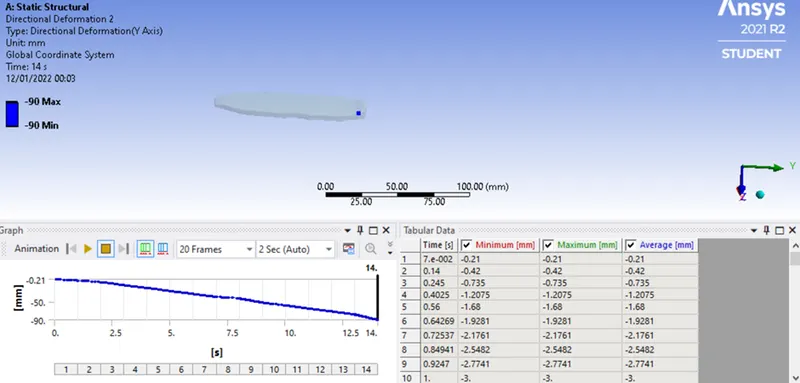
Fig.9 Displacement of end vertex proving the displacement of the workpiece by 90 mm
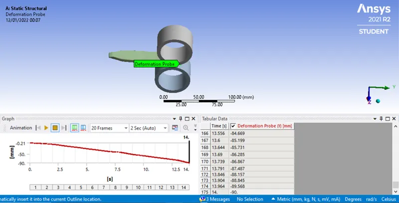
Fig. 10 Displacement probe indicating the workpiece has been displaced by 90 mm
CONCLUSION
Numerical analysis was conducted for investigating the von mises stress, equivalent plastic strain and directional deformation along Z direction. The workpiece has undergone sever plastic deformation. As a result, high stress of 3485.6 MPa has been developed in the material. The material has flowed to the z direction increasing the width of the material. The equivalent plastic strain and width of the material are 2.116 and 7.1573 mm respectively. The workpiece was proved to move by 90 mm using both the directional deformation of end vertex of the workpiece and displacement probe. Fine meshing was not carried out since the analysis was performed in Ansys student version.