Week 4- Rolling operation
Rolling operation analysis on Copper Workpiece:
Aim: To perform Rolling opeartion structural analysis on workpiece made up of Copper Alloy NL.
Introduction:
Rolling:Within manufacturing metal forming category,Rolling is one of the most widely used process were metals are deformed in plastic zone with the help of Rollers having desired material characterstics, to make permanent thin sheets out of metals during large scale sheet production used in cars,aircrafts etc. other places.
Rolling can be futhur classified into two categories depending on the tempratures of metal workpiece:
a) Hot Rolling:If temprature of metal workpiece is above its recrystalline temprature during Rolling operation, it is known as hot rolling process.
b)Cold Rolling:If temprature of metal workpiece is below its recrystalline temprature during Rolling operation, it is known as cold rolling process.
A pair of Rollers rotating in opposite sense is provided in rolling mills, between which the workpiece is placed such that it undergoes plastic deformation, thereby making it thin sheet so that it can be used at various places.
Steps followed:
1) Material selection:
For workpiece Copper Alloy Nl is chosen with the properties shown in the image below:
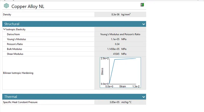
Workpiece material selection:
Copper alloy is selected for workpiece
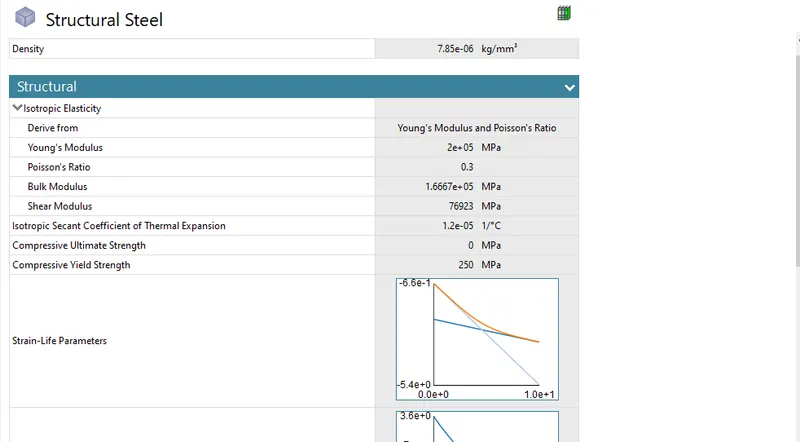
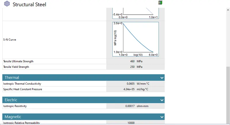
For Roller pairs Structural Steel is choosen with properties in the image below:
Material selection for both the rollers:
Structural steel Properties:
2) Geometry:
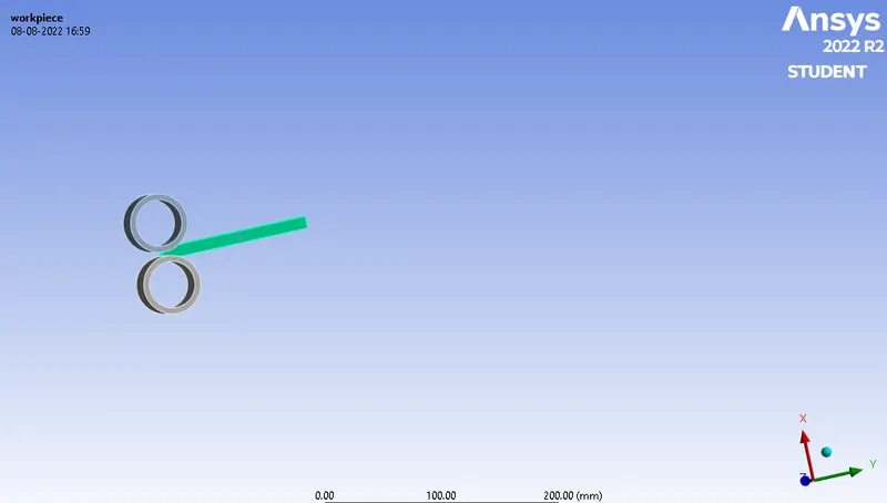
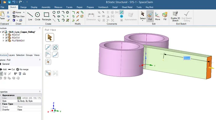
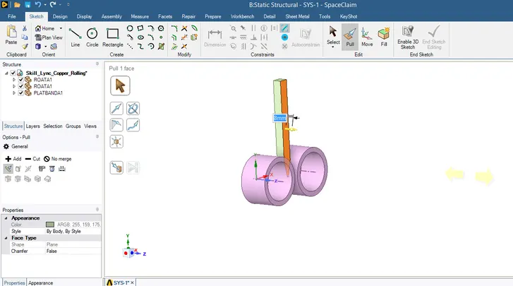
After Importing the CAD model of Roller pairs & Workpiece,length of the workpiece is increased by 60mm and its size decreased on both sides by 8mm.
Length increased by 90mm:
Width decreased by 8mm on both sides:
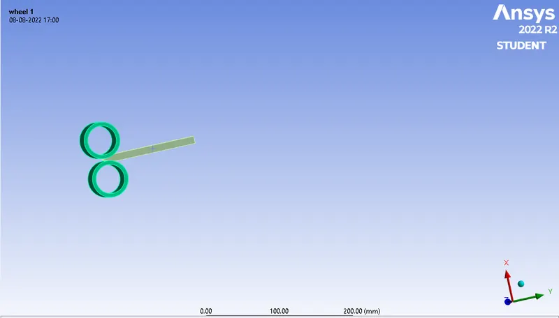
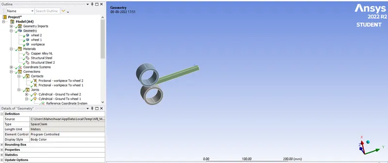
3) Go to Model in menu and right click select update, to change the geometries of model as per changes doen in geometry above. After it just open the model & rename the parts as wheel 1,wheel 2 and workpiece:
4)Contacts:
Select both the contact already present there just flip them using right click and Rename Based on defination using the right click mouse button.
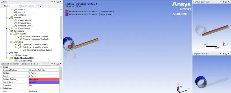
Select the Frictional-Workpiece to Wheel 1 from contact settings & choose in Target Wheel 1 outer face area which is in contact with workpiece is selected while in Contact area of upper face of workpiece is selected.
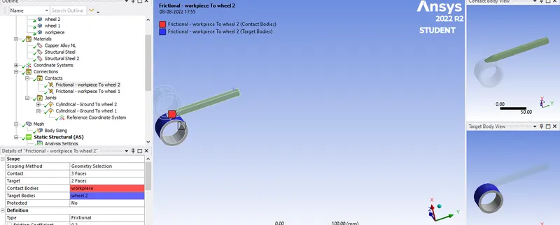
Same is repated for Wheel 2 & workpiece:
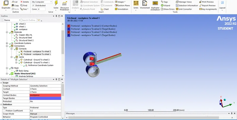
Select both the contacts using shift key from keyboard & apply Frictional Type contact to both with 0.2 frictional coefficient with Formulation as Augumented Lagrange. Normal stiffness:Factor is selected with Normal Stiffness Factor of 0.1 and Interface Treatments:Add Offset Ramped Effects choosen.
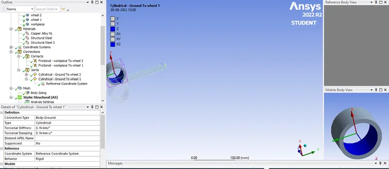
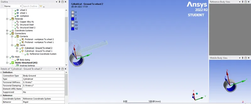
Insert Cylindrical Type Body-Ground Joints by right click on contacts and selecting the inner area of each Roller, do this two times. Change the direction of Z axis from Refrence Coordinate System opposite to what was there intially.
5)Meshing:
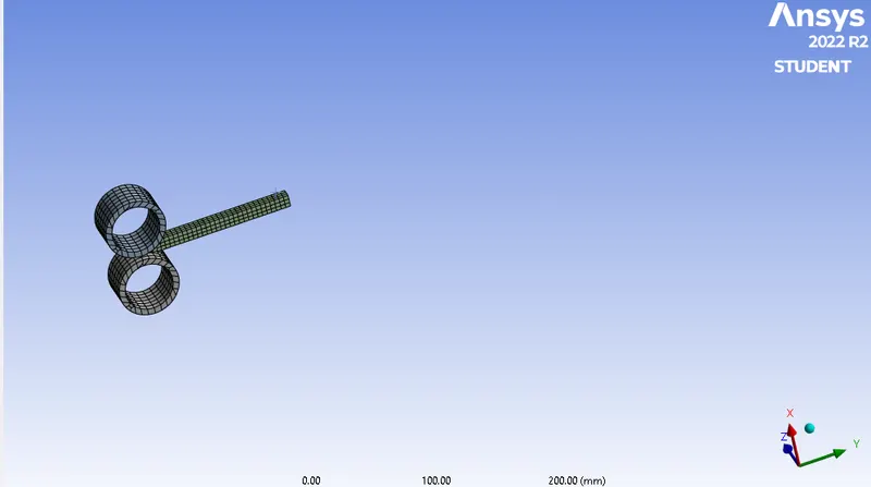
Used Mesh size for Rollers are Default, however with Workpiece Body Sizing of 4mm to each element used.
Workpiece mesh size 4mm:
6)Boundary Canditions:
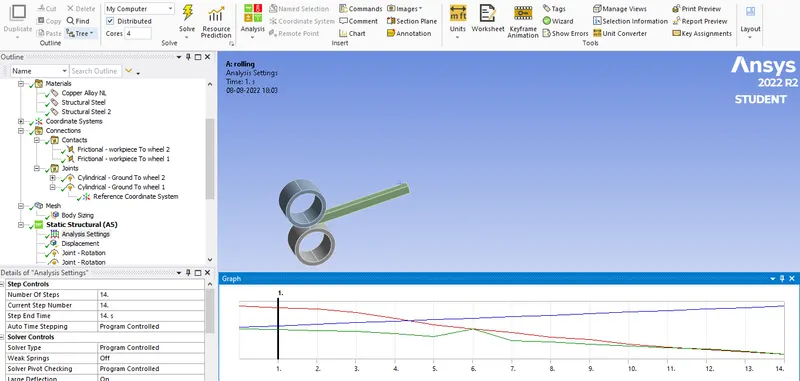
a) Analysis Settings: From Analysis setting select number of steps as 14 then with the help of Shift key select 14 steps with Large Deflection On. As this is Non Linear problem so select Non Linear Controls with Stablization Constant with Energy Dissipation as 0.1.
Analysis Setting:
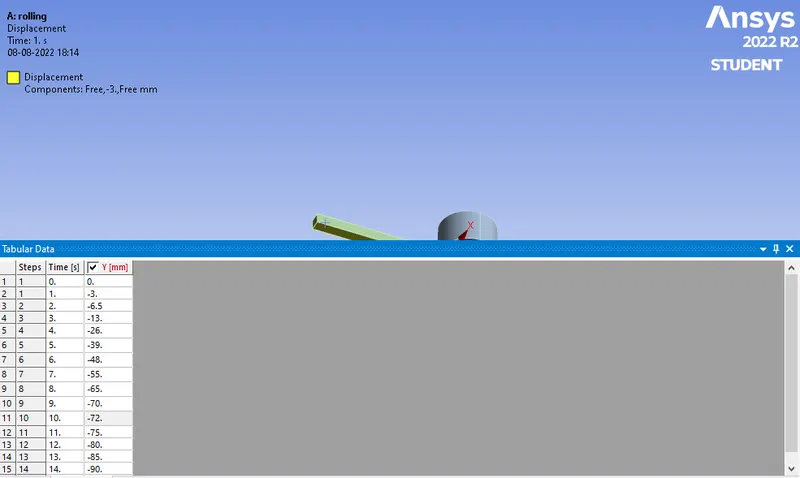
b)Displacement: A displacement is given on workpiece by selecting its 2 faces in Tabular format along negative Y axis
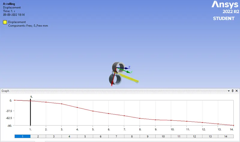
Displacement tabulation values:
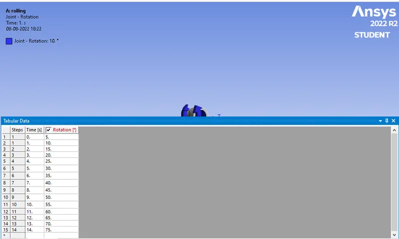
c)Rotation:
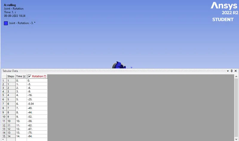
Along Z axis Rotation angles are given for the 14 steps on each Roller such that they rotate in opposite sense with respect to another Roller during the Rolling process.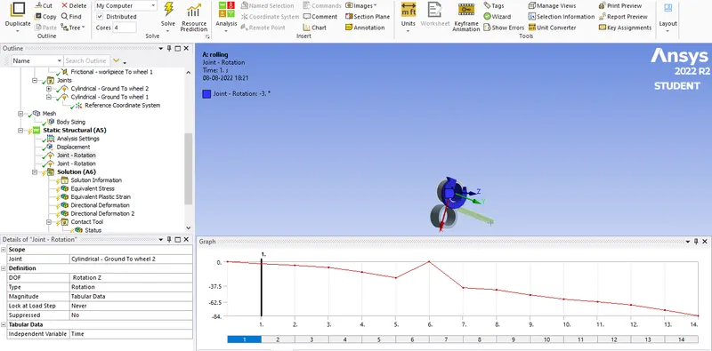
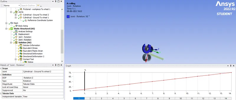
Rotaion tabulation values
Results:
Equivalent Stress for the entire setup:
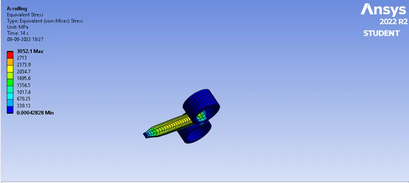
Maximum Equivalent Stress for the entire setup: 3052.1MPa
Equivalent Plastic Strain of Workpiece:
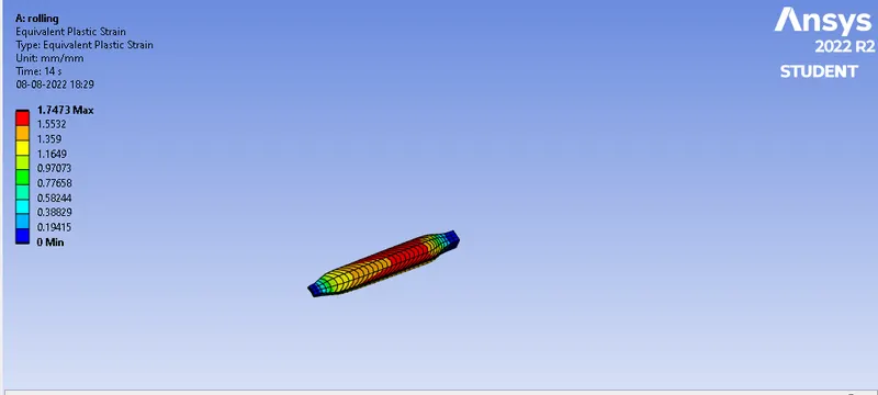
Maximum Equivalent Plastic Strain for the Copper Alloy NL Workpiece:1.7473
Maximum Directional Deformation for the Workpiece along Z axis:
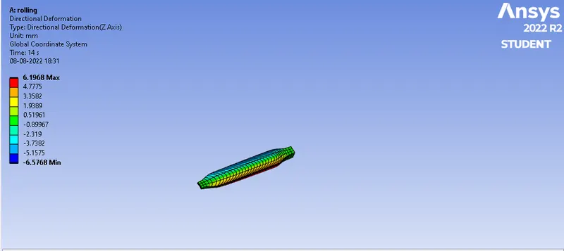
Maximum Directional Deformation of Copper Alloy NL Workpiece:6.1968mm
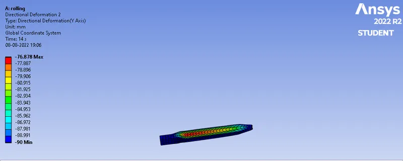
Maximum Directional Deformation of front face of workpiece along negative Y axis:
Maximum Directional Deformation of workpiece along Y axis: -90mm
Conclusion:
- It can be seen from the figure above of Maximum Directional Deformation of workpiece along Y axis is -90 mm which is equal to the maximum displacement input on the workpiece along negative Y axis, therefore maximum displacement of edge of workpiece is 90mm along negative Y axis proved.