Week 4- Rolling operation
Rolling Operation
OBJECTIVE:-
To simulate the rolling operation on a workpiece made of copper and to obtain the results of Equivalent Stress, Directional Deformation and Equivalent Plastic Strain of the model and the sheet.
INTRODUCTION:-
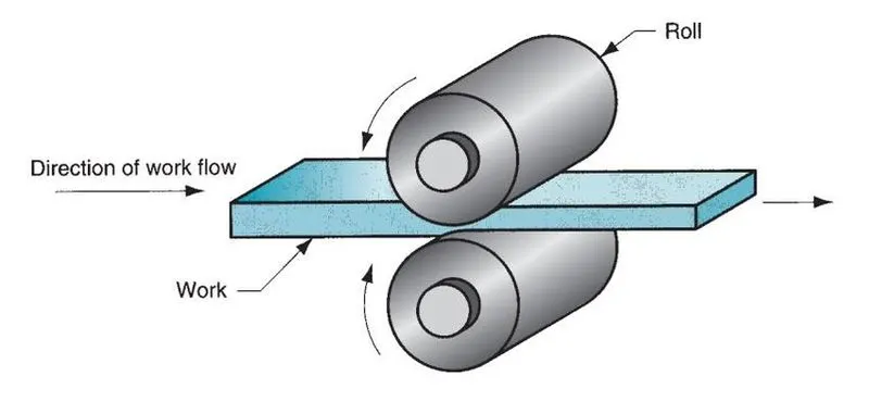
Rolling is the process of reducing the thickness or changing the cross section of a long strip by compressive forces applied through a set of rolls. In addition to flat rolling, shape rolling is used to make products with various cross sections. Products made by rolling include: (a) plate, sheet, foil, rod, seamless pipe, and tubing (b) shape-rolled products, such as I-beams and structural shapes and (c) bars of various cross section.
PROCEDURE:-
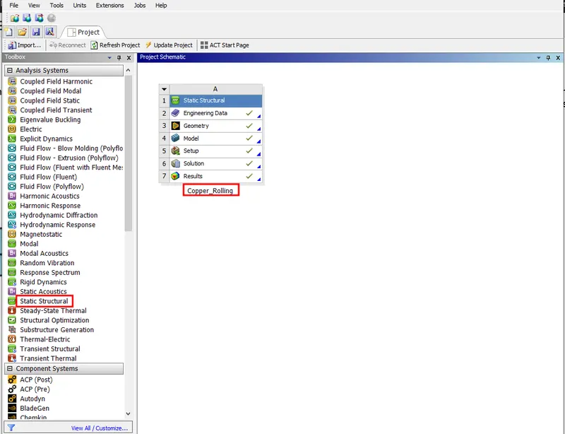
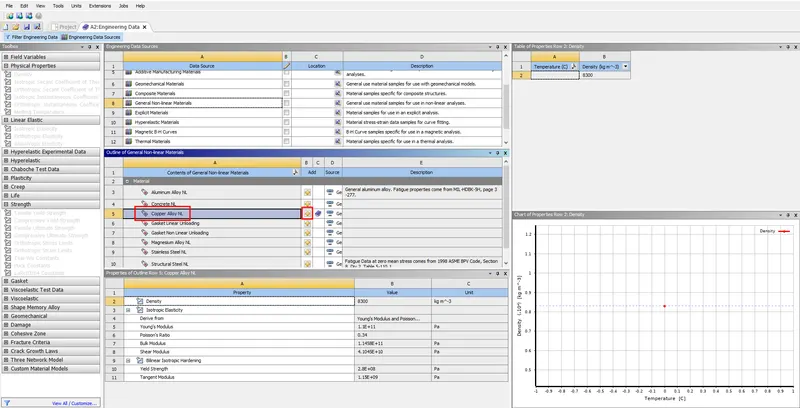
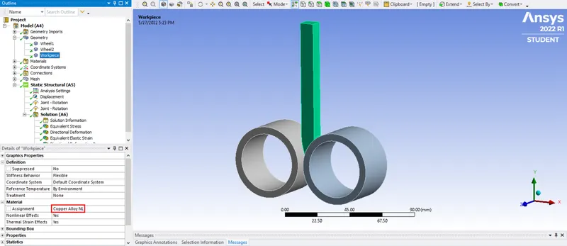
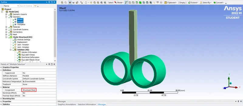
1) Double click on Static Structural tab to start with a new setup and add the material required for the simulation. Structural steel and Copper alloy NL will be used for rollers and workpiece respectively, we can find this alloy material under General Non-Linear Materials.
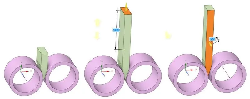
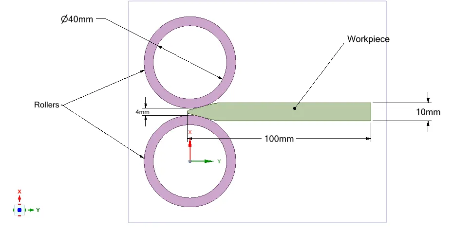
2) Import the model geometry and open it in Spaceclaim to check the model and edit it further if needed. Here length of the workpiece is increased by 60mm and width is decreased by 8mm from both the sides by pulling the faces.
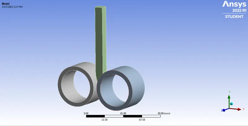
3) Update the model and open it in ANSYS Mechanical. Rename the components and assign the materials accordingly.
4) Define frictional contacts between rollers and workpiece. Here the roller is specified as target and workpiece is specified as contact as shown.
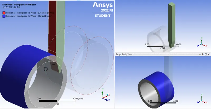
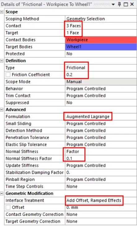
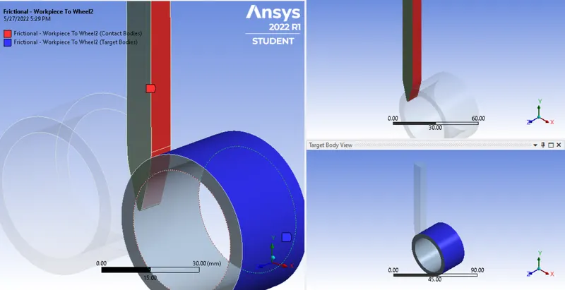
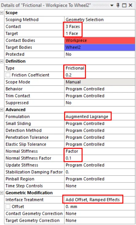
5) Define joints for the rollers as cylindrical joint and adjust the direction of Z-axis in Reference coordinate system for rollers if needed according to required direction of rotation for rollers.
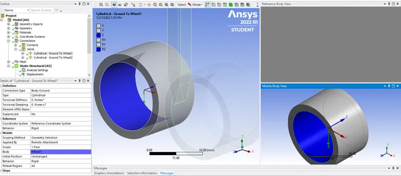
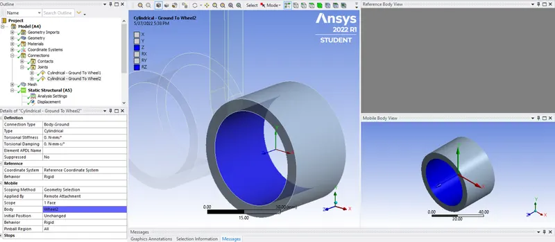
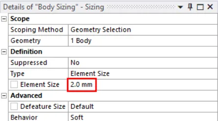
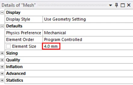
6) Mesh the model with 4mm element size for rollers and define Body Sizing for workpiece to mesh it with 2mm element size as shown.

7) Define analysis setting for the simulation and specify values for various parameters as shown in image.
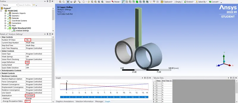
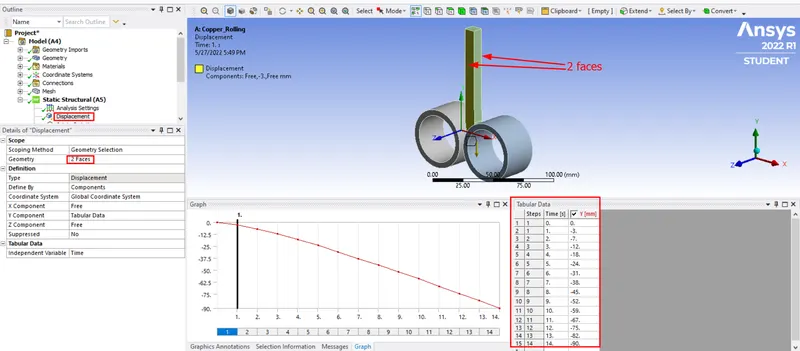
8) Now define displacements and joint forces for model components. We have given displacement of 90mm to the workpiece in -Y direction in 14 steps.
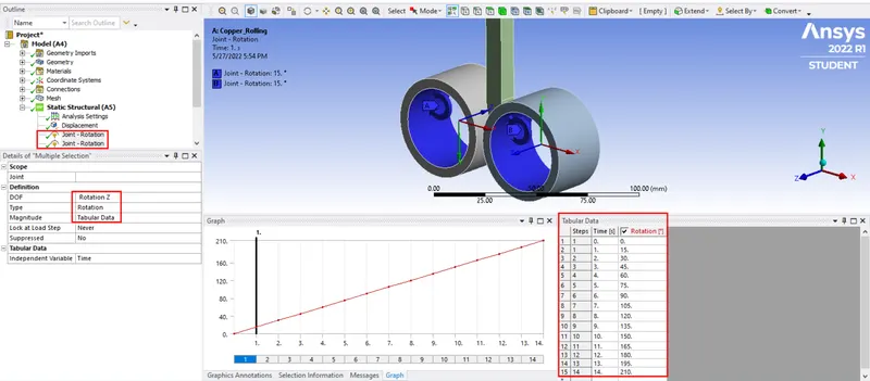
Define rotation for the rollers w.r.t Z-axis and the direction of rotation for both the rollers has to be in opposite direction as shown. We have given 210 degree rotation to both the rollers in 14 steps.
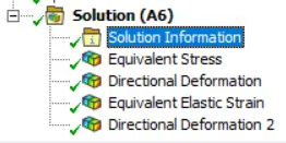
9) Request for solution regarding Stress, Strain and Deformation as asked for which is shown in the image below.
RESULTS:-
Force Convergence -
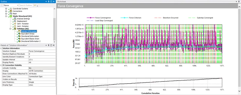
Force convergence graph shows that it took 1371 iterations in total for problem to solve with convergence and run the simulation with 14 load steps.
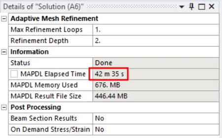
Solution run time is coming out to be 42min. 35sec.
Equivalent Stress -
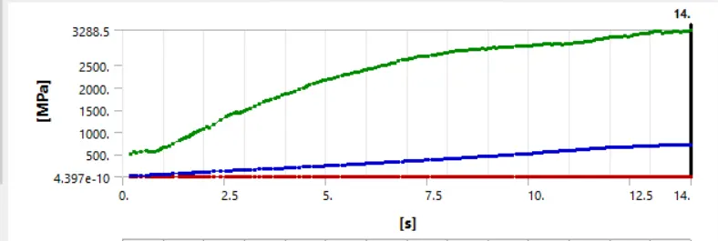
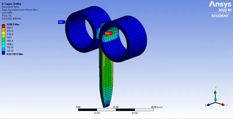
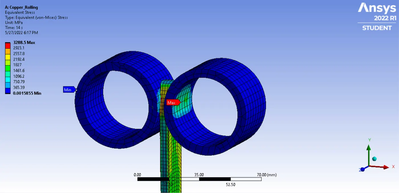
The max. equivalent stress value that we are getting here is 3288.5Mpa
Equivalent Elastic Strain for Workpiece -
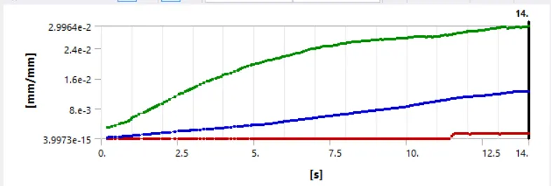
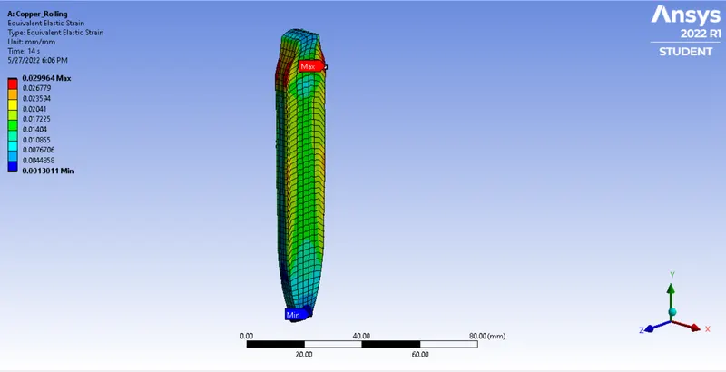
Max. equivalent elastic strain for workpiece is coming out to be 0.029964mm
Directional Deformation in Z-direction for Workpiece -
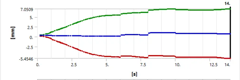
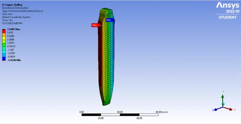
Max. directional deformation for the workpiece is 7.0482mm in Z-direction.
SIMULATION:-
Displacement of the workpiece -
As we can see in the requested output list, we have rquested for a parameter Directional Deformation 2. This one is defined to prove that the total displacement given to the workpiece is 90mm. What we have done here is we selected bottom 3 faces of the workpiece and asked for Directional Deformation for these 3 faces in Y-direction as shown.
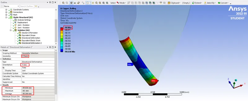
It can be clearly seen from the image that the max. deformation for these 3 faces is 90mm in -Y direction so this result proves that total displacement given to the workpiece is 90mm.