Week 4- Rolling operation
objective : To perform the simulation of the given copper wire rolling and obtaining the desired result of displacement, stresses and strain as required.
Procedure:
Setting up the simulation
To set up the simulation, first we need to import all the required material card such as structural steel for the rollers and copper alloy for NL for wire segment.
The above material can be found in the general non- linear material library.
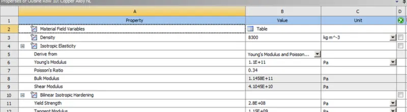
Copper Alloy NL
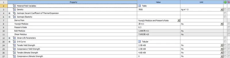
Importing geometry
Next, we import the geometry which has been provided and open it in space claim and modify it slightly so that the length is 60mm and width is reduced on each side by 8mm.
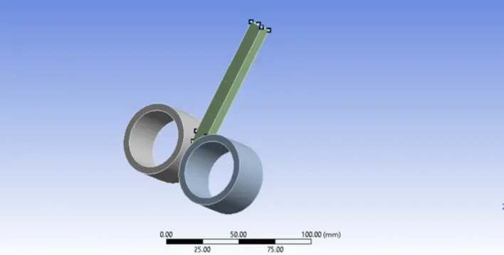
material definition:
The material copper allow NL is assignment to the wire segment and structural steel is assigned to rollers, then we will open Ansys mechanial to set up the rest of the simulation. To set up the contact we go to connection-->contacts and open the contact card.
we will create 2 contacts
1) Between roller 1 and the wire
2) Between roller 2 and the wire
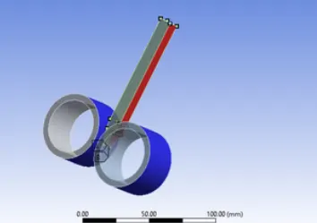
type=frictional
coefficient of friction =0.2
formulation=augmented language
Normal stiffness factor=0.1
interface treatment = Add offset, ramped effects
Next we mesh the components
A body sizing of 5mm is applied on the rollers and a body sizing of 4mm is applied on the wire segment.
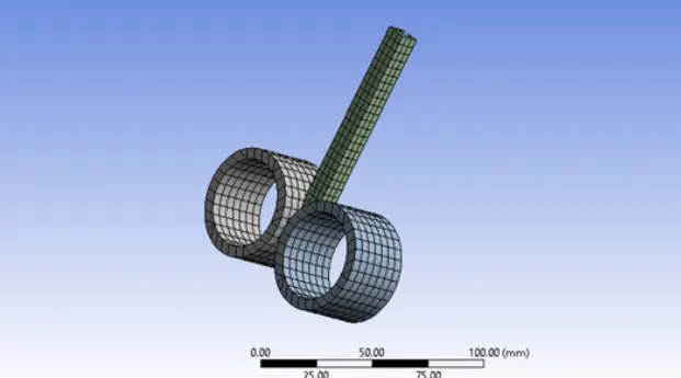
creation of joints:
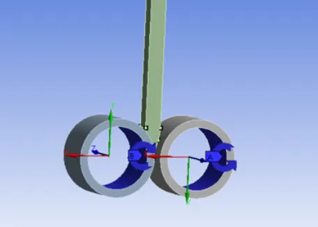
we create cylindrical joints for both the rollers individually with the surface as the inside face of the rollers.
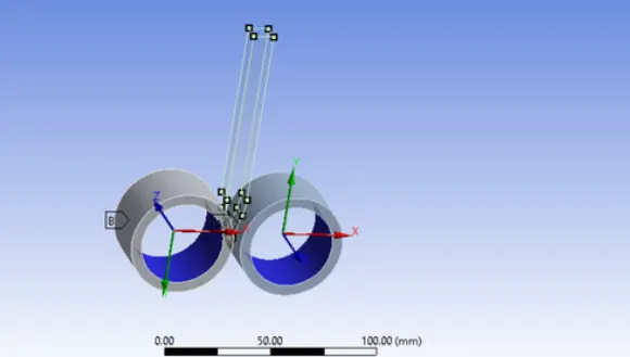
The axis of rotation is inverted in both rollers to facilitate counter rotation so that the wire get pressed and flattened while it moves down.
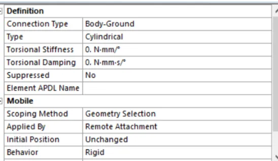
Analysis setting:
Next we got to analysis setting to get up the kinematics of the simulation. The analysis is run for 14 steps using the following condition .all the steps are chosen and the following criteria are enterd as shown.
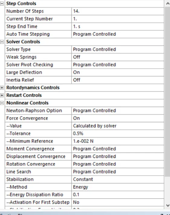
large deflection=ON
Stablization= constant
energy dissipation ratio=0.1
we will provide a motion to the copper wire in the y-direction so that it is pushed into the rollers. the wire is given motion in the Y-direction only with the following values according to the motion of the rollers.
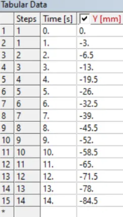
we must be careful while entering this data as it must correlate with the rotary motion of the roller or else the simulation will ecome unstable. The face selected in yellow are chosen to give the linear motion to.
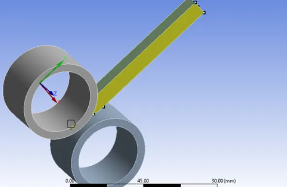
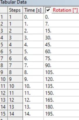
Next we provide rotary motion to the rollers which have been earlier defined as joints. they have the opposite directions and hence we input the same value of angular displacement with respect to time so that they move counter-rotary to each other.
The following values have been inputted which in accordance with the motion of the wire.
output parameter:
The following parameters are selected for output from the simulation.
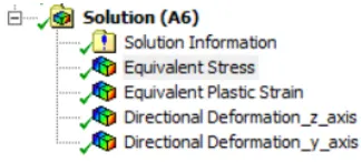
The equivalent stress and strain are selected for the wire segment.
A part from this we choose directional deformation along the Z-axis to get the wire that will get flattened we also choose the directional deformation for the top surface of the wire to get reading of the translation of the wire segment obtained by pushing it down into the rollers.
Running the simulation:
Next we run the simulation . the simulation takes about 1 sec to run as we can see from the run time
post processing:
equivalent stress:
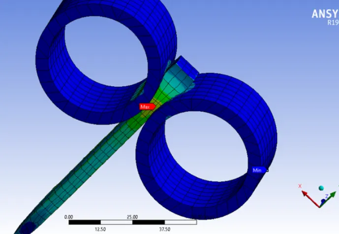
A peak stress of 3233.7Mpa is obtained in the wire segment
equivalent plastic strain:
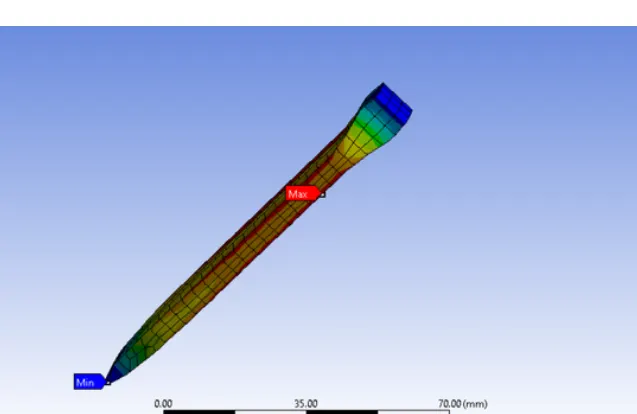
A maximum plastic strain of around 1.2867 is obtained in the wire segment
directional deformation in Z-AXIS:
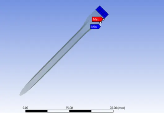
A maximum displacement of 84.5mm in the Y-direction occurs as per the displacement we have inputted for the wire segment as seen in the image above
Conclusion:
Hence the copper wire rolling analysis simualtion has been performed successfully and the desired output has been obtained.