Week 4: Project - Steady state simulation of flow over a throttle body
Objective:
To perform Steady-state simulation of fluid flow over a throttle body
To post convert the results and show pressure and velocity contours for the both the cases
To show the plots for pressure, velocity, mass flow rate and total-cell-count
Throttle body:
A throttle is the mechanism by which fluid flow is managed by constriction or obstruction. A throttle body is essentially a large air valve that sits between the intake manifold and the air intake pipe. An engine has one throttle body, which bolts to the intake manifold’s plenum (the large air cavity in the center).A throttle body controls airflow into the engine, a crucial factor for controlling the air/fuel ratio
Step Up
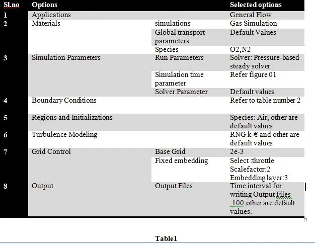
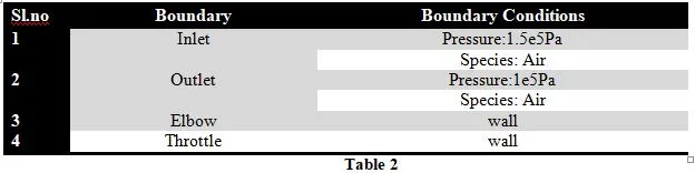
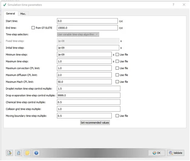
Simulation parameter
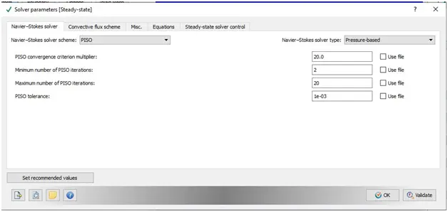
Solver Parameter
Boundary Conditions
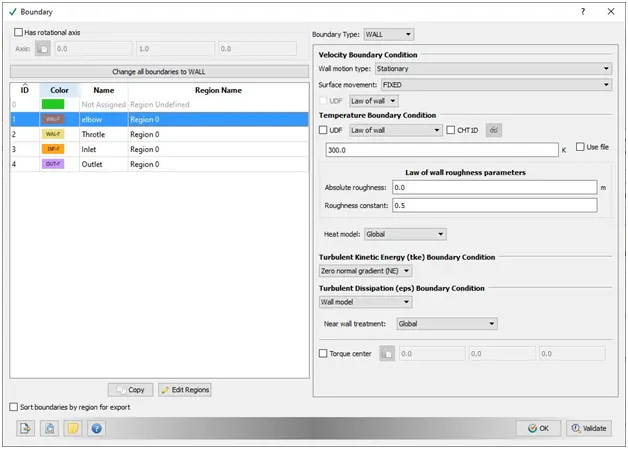
Elbow conditions
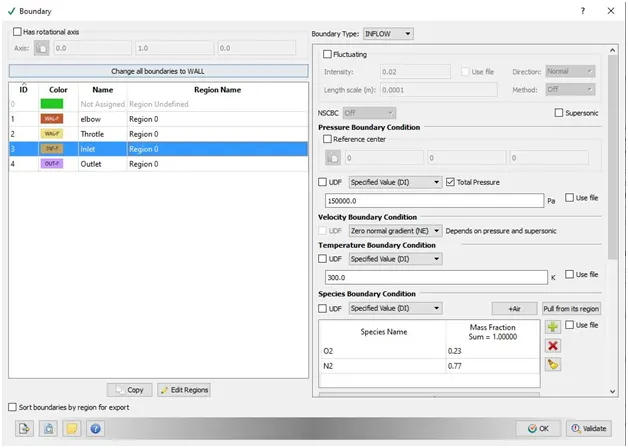
Inlet Conditions
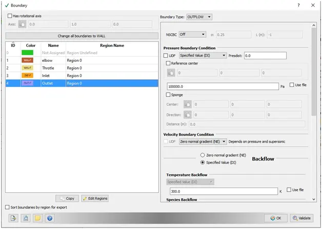
Outlet Condition
Base Grid
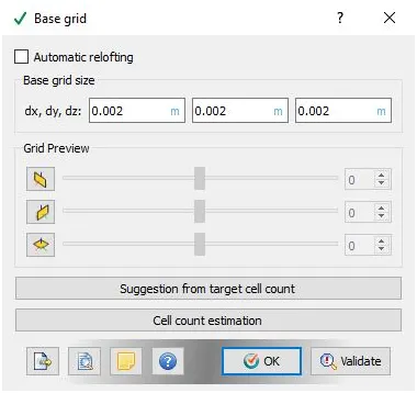
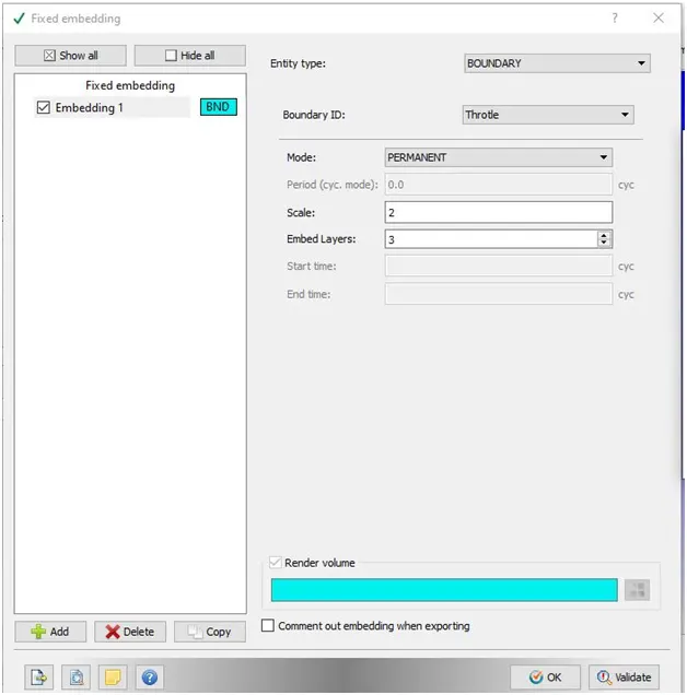
Meshing
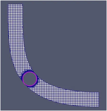

Plots
Bound_id_3 is inlet
Bound_id_4 is outlet
MassFlowRate
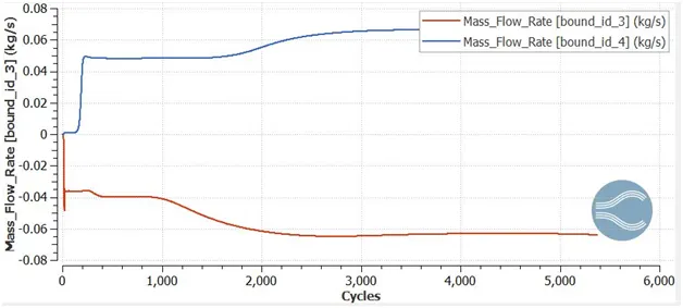
we observe from the plot that mass_flow_inlet is equal to outflow (i.e 0.063kg/s),it converges after 4000 cycles
Velocity
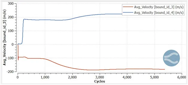
we observe that inlet velocity is equal to outlet velocity that is 217m/s, it converges after 4000 cycles
Pressure
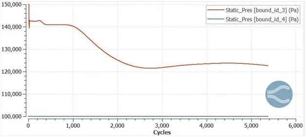
The inlet pressure eventually decreses because their is obstruction of throttle,the engergy is observed by the throtle
Total_cell_count
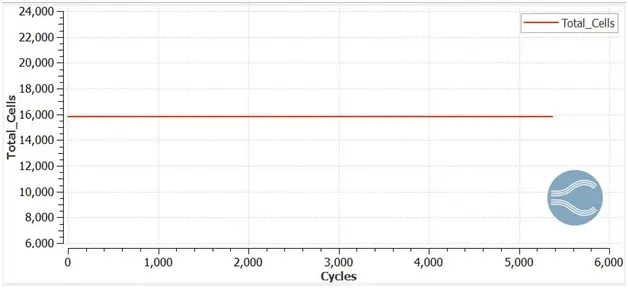
It takes 16000 cells to simulate the steady state simulation
Animation
Streamline flow over throtle
velocity
Pressure
Conclusion
we studied that how the fluid flows inside the elbow with throtle fixed at the center,the flow nearly converges after 4000 cycles