Week 4:- Pin Unit Design Challenge
Fixed Pin Unit and Retractable Pin Unit Design
Pin Unit
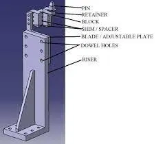
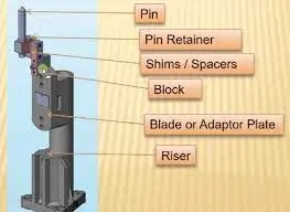
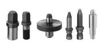
Fixture 4-42. Plain fixture keys and step fixture keys.
What Is Jig & Fixture Design?
Jigs and fixtures are manufacturing tools that are used to produce identical and interchangeable components. These workholding and tool guiding devices are designed for use in the machining and assembly of parts.
To get the greatest benefit from jigs and fixtures, a basic understanding of their construction is necessary. Jigs and fixtures are identified one of two ways: either by the machine with which they are identified or by their basic construction. A jig, for instance, may be referred to as a “drill jig.” But if it is made from a flat plate, it may also be called a “plate jig.” Likewise, a mill fixture made from an angle plate may also be called an “angle-plate fixture.” The best place to begin a discussion of jig and fixture construction is with the base element of all workholders, the tool body.
Advantages of Jigs and Fixtures
In manufacturing operations, it's important to meet the higher demands of customers. This means producing quality products as fast and efficiently as possible. Jigs and fixtures help make manufacturing processes more efficient and precise.
By utilizing jigs and fixtures in machining processes, manufacturers benefit from:
- increased production
- decreased manufacturing costs
- improved product consistency
- improved assembly line safety
- a reduction in non-productive hours
- reasonable automation capabilities
- interchangeability and accuracy
Jigs vs. Fixtures: What's the Difference?
While jigs and fixtures work together, these are two distinct tools used in mass production processes. The two terms are often used incorrectly as synonyms but serve different purposes.
A jig controls and guides the cutting tool to work at a predefined location on a workpiece. Fixtures are used for supporting and locating a workpiece. Fixtures do not guide the tool on a workpiece like a jig.
Jigs are typically lighter than fixtures, which need additional force to stand up to cutting force and vibration. While fixtures require clamping and accessories, a jig can be held or fixed to a table depending on the application.
QUICK-FINDS:
Types of Jigs and Fixtures
This section serves as a comprehensive guide to understanding the design of jigs and fixtures, and how each of these critical work holding devices operates in practice. Carr Lane Mfg. Co. has been a market leader in jig and fixture components for 70 years. Learn more about the various types of jigs and fixtures developed by Carr Lane Mfg. Co.
TOOL BODIES
The tool body provides the mounting area for all the locators, clamps, supports, and other devices that position and hold the workpiece. The specific design and construction of a tool body are normally determined by the workpiece, the operations to be performed, and the production volume. Economy is also a key element in good design.
The three general categories of tool bodies are cast, welded, and built up, Figure 4-1. Each type of construction can be used for any workpiece, but one is often a better choice than the others. The first step toward an economic design is to know and weigh the strengths and weaknesses of each.
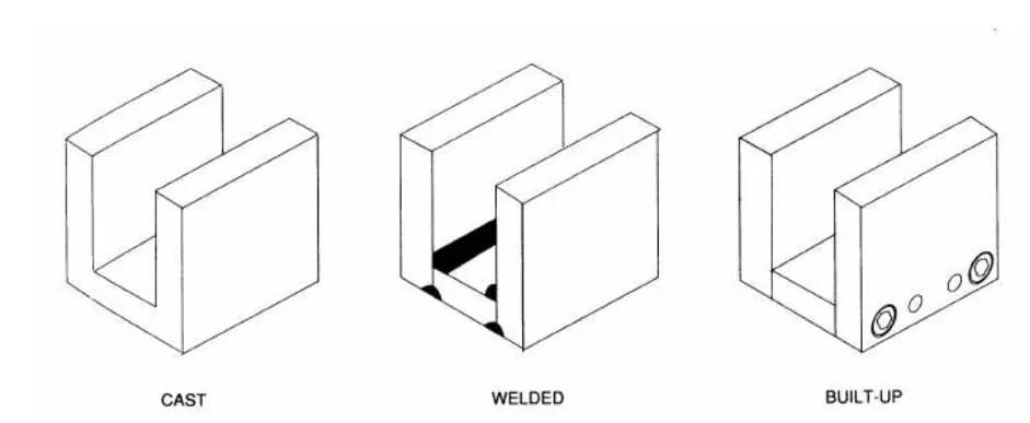
Figure 4-1. The three basic forms of tool-body construction are cast, welded, and built up.
Cast tool bodies are made in a variety of styles and types. The most common casting materials for tool bodies include cast iron, cast aluminum, and cast magnesium. Cast materials occasionally found in specialized elements for tool bodies, rather than in complete tool bodies, are low-melting-point alloys and epoxy resins.
Cast tool bodies can have complex and detailed shapes. Such shapes require fewer secondary machining operations. Cast materials dampen vibration. They are most often found in relatively permanent workholders; workholders not subject to drastic changes. Cast tool bodies have three major drawbacks: (1) they are not easily modified for part changes; (2) their fabrication cost is high; (3) they require a lengthy lead time between design and finished tool body.
Welded tool bodies are also made from a wide variety of materials. The most common welded tool bodies are made of steel or aluminum. Welded tool bodies are inexpensive to build and they are usually easy to modify.
They require minimal lead time. Welded tool bodies are also quite durable and rigid. They provide an excellent strength-to-weight ratio.
Heat distortion is the major problem with welded tool bodies. For best results, and to ensure stability of the tool body, welded tool bodies should be stress relieved before final machining and use. Be aware, however, this will add to the preparation lead time and cost, as well. Another problem with welded tool bodies is in the use of dissimilar materials. When a steel block, for example, is added to an aluminum tool body, it should usually be attached with threaded fasteners rather than by welding to the body.
Built up tool bodies are the most common tool body today. These tool bodies are very easy to build, and usually require the least amount of lead time between design and finished tool. The built up tool body is also easy to modify for changes in the part design. Like the welded body, built up tools are durable and rigid, and have a good strength-to-weight ratio. Depending on the complexity of the design, the built up tool body may be the least expensive to construct.
Built up tool bodies are usually made of individual elements, assembled with screws and dowel pins. The built up tool body is often used for precision machining operations, inspection tools, and some assembly tooling.
Preformed materials can often reduce the cost of machining tool bodies. These preformed materials include precision tooling plates, tooling blocks, risers, cast sections, and angle brackets. Other materials include ground flat stock, drill rod, or drill blanks, and also structural sections such as steel angles, channels, or beam.
The major advantage to using preformed and standard parts is the reduced labor cost in fabricating the workholder.
TOOLING PLATES
Tooling Plates
Tooling plates are standard, commercially available base elements used to construct a variety of different workholders. Like other fixturing elements, these plates come in several variations to meet most fixturing requirements.
Rectangular Tooling Plates: Of all standard tooling plates, the rectangular ones, Figure 4-2, are the most popular. Their rectangular form works well for a wide variety of workholders. The plates come in a wide range of sizes, from 12” x 16” to 24” x 32”. Rectangular tooling plates are made of ASTM Class 40 gray cast iron, machined flat and parallel.
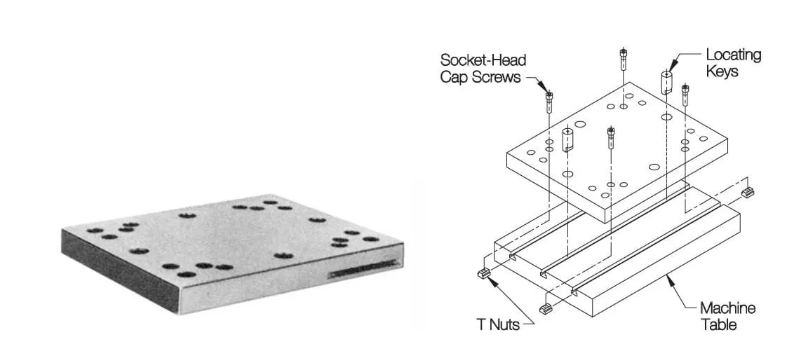
Figure 4-2. Rectangular tooling plates are available in a full range of standard sizes, for vertical milling machines.
Round Tooling Plates: Another tooling-plate variation is the round tooling plate, Figure 4-3. Round tooling plates work well on rotary or indexing tables. These tooling plates are available in 400mm, 500mm, and 600mm diameters. They are made of ASTM Class 40 gray cast iron, and have a series of mounting holes.
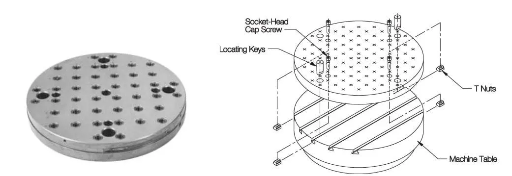
Figure 4-3. Round tooling plates are ideal for rotary or indexing tables.
Square Pallet Tooling Plates: Square pallet tooling plates, Figure 4-4, are another form of tooling plate.
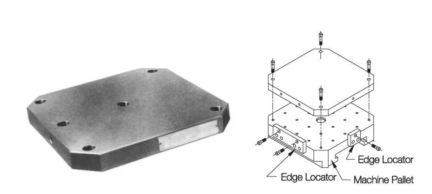
Figure 4-4. Square pallet tooling plates are available for all horizontal machining centers with standard square pallets.
The square shape is ideal for palletized arrangements where a square tooling base is necessary. Square tooling plates come in five sizes to fit standard machining-center pallets 320mm, 400mm, 500mm, 630mm, and 800mm square. Plates are made of ASTM Class 40 gray cast iron.
Rectangular Pallet Tooling Plates. Similar to square pallet tooling plates, except made for rectangular machining-center pallets 320 x 400mm, 400 x 500mm, 500 x 630mm, and 630 x 800mm. Figure 4-5 shows this type, and how it can also be mounted on a square pallet by adding a spacer.
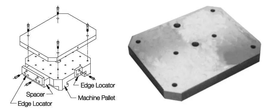
Figure 4-5. Rectangular pallet tooling plates are for machining centers with rectangular pallets, or square pallets requiring a larger mounting surface.
Angle Tooling Plates. The angle tooling plates, Figure 4-7, are another useful tooling plate. These vertical plates allow mounting a large part approximately on the pallet’s center-line. These plates are made to fit machining-center pallets 400mm, 500mm, 630mm, and 800mm square. Angle tooling plates are made from ASTM Class 45 cast iron.
Platform Tooling Plates. Platform tooling plates are a variation of the square tooling plate. These plates are specifically designed for a mounting surface that must be elevated off the machine-tool table. As shown in Figure 4-6, the raised mounting surface permits easier access to the workpiece with horizontal machining centers. The added height provides the necessary clearance for the machine-tool spindle. The design also eliminates the dead space between the machine-tool table and the minimum operating height of the spindle.
Added height is also beneficial when machining short parts on a vertical machining center to avoid Z-axis limit errors. Platform tooling plates come in three sizes for 500mm, 630mm, and 800mm pallets. Platform tooling plates are made of ASTM Class 45 cast iron.
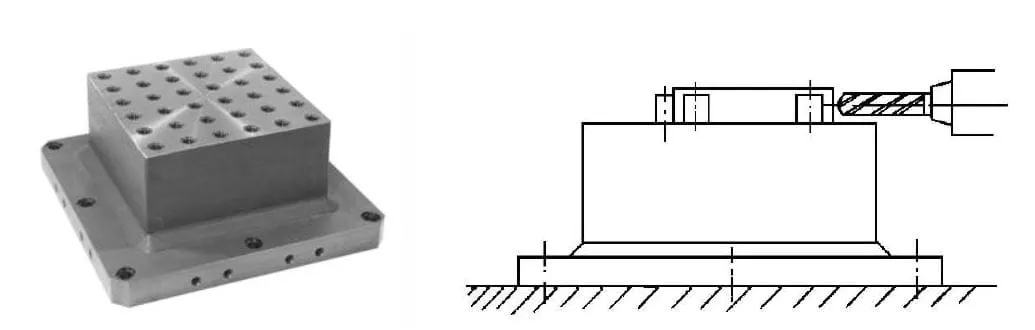
Figure 4-6. Platform tooling plates provide a raised horizontal mounting surface for easier workpiece access on horizontal machining centers.
Angle Tooling Plates. The angle tooling plates, Figure 4-7, are another useful tooling plate. These vertical plates allow mounting a large part approximately on the pallet’s centerline. These plates are made to fit machining-center pallets 400mm, 500mm, 630mm, and 800mm square. Angle tooling plates are made from ASTM Class 45 cast iron.
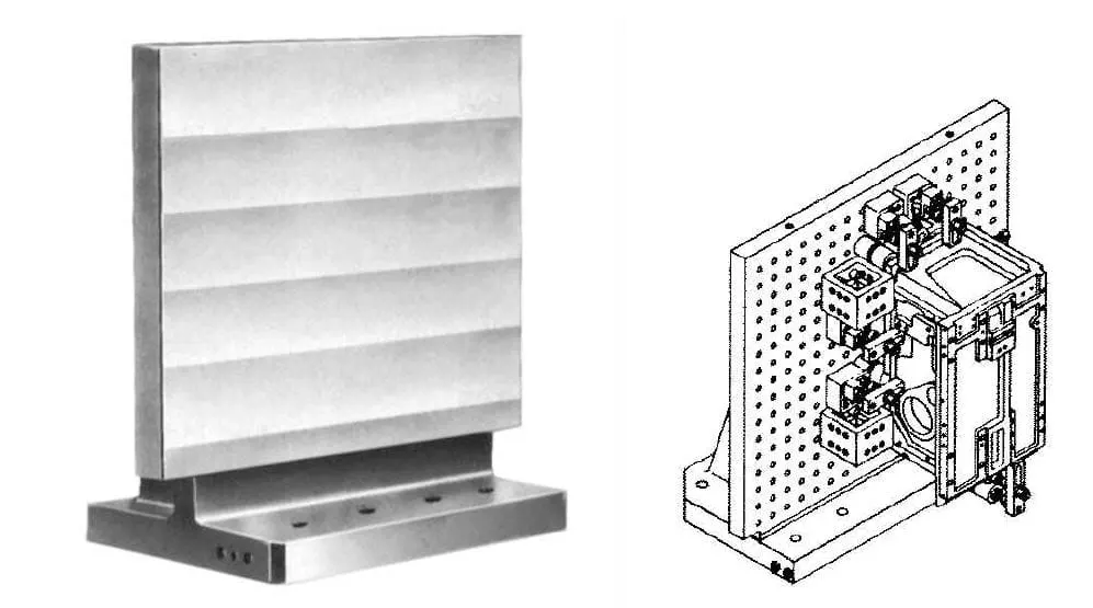
Figure 4-7. Angle tooling plates provide a vertical mounting surface on horizontal machining centers, ideal for extremely large parts.
TOOLING BLOCKS
Tooling Blocks
Tooling blocks are often used on horizontal machining centers. The most-common tooling blocks are the two-sided and four-sided styles. These blocks work both for mounting workpieces directly, or for mounting other workholders. All working faces are accurately finish mac hined to tight tolerances, and qualified to the base.
Dual mounting capability, Figure 4-8, allows both JIS mounting (locating from two reference edges) and DIN mounting (locating from center and radial holes).
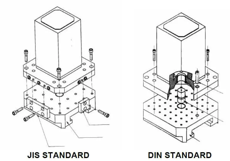
Figure 4-8. Tooling blocks can be located either using two reference edges (JIS standard) or using center and radial holes (DIN standard).
Two-Sided Tooling Blocks. The two-sided tooling block, Figure 4-9, is for mounting workpieces or workholders on two opposite sides. Two-sided tooling blocks work well for fixturing two large workpieces.
These tooling blocks come in five different pallet sizes: 320mm, 400mm, 500mm, 630mm, and 800mm.
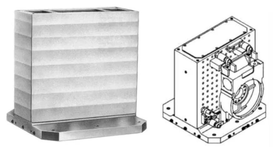
Figure 4-9. Two-sided tooling blocks have two identical wide mounting surfaces for fixturing large parts.
Four-Sided Tooling Blocks. The four-sided tooling block, Figure 4-10, mounts workpieces or workholders on four identical sides. Four-sided tooling blocks, with their four working surfaces, are typically chosen to maximize production. These tooling blocks are available in five different pallet sizes: 320mm, 400mm, 500mm, 630mm, and 800mm.
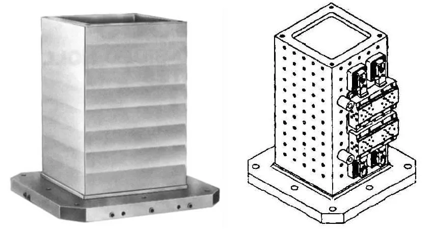
Figure 4-10. Four-sided tooling blocks have four identical mounting surfaces for fixturing medium-size parts.
PRECISION CAST SECTIONS
Precision Cast Sections
Precision cast sections come in a variety of shapes and sizes. Most cast sections are available in standard lengths of 25.00”, and all sizes and styles are available in precut 6” lengths, with squareness and parallelism within .005”/foot on all working surfaces. The sections can also be ordered cut to any specified length. The two common cast-section materials are cast iron and cast aluminum. The cast iron sections are made of ASTM
Class 40 cast iron with a tensile strength of 40,000 to 45,000 psi. The aluminum sections are 319 aluminum with a tensile strength of 30,000 psi. Cast elements are used mainly for major structural elements of jigs and fixtures rather than as accessory items. Depending on the workholder design, it is possible to build a complete workholder by simply combining different sections.
T Sections. T-shaped cast sections, as shown in Figure 4-11, are made in two different styles: equal T
sections and offset T sections. Equal and offset T sections come in 6.00” lengths, or 25.00” lengths. As shown in Figure 4-12, both the equal and offset T sections have basically a square cross-sectional profile where width and height are the same. The major difference between the two styles, as shown, is the position of the vertical member in relation to the horizontal portion. The vertical member of the equal T section is positioned in the middle of the bottom portion. It is moved to one side on the offset T section. Both styles are available in five different sizes ranging from 3.00” x 3.00” to 8.00” x 8.00”. The web thickness of these sections is proportional to the overall size, ranging from .63” to 1.25”. Figure 4-13 shows an application where either style T section can be used.
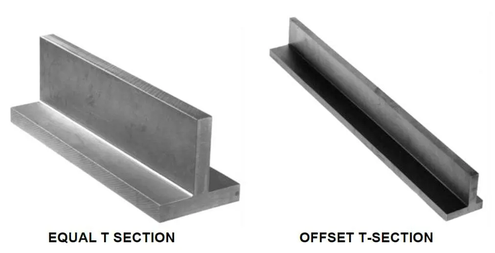
Figure 4-11. T sections are made in two styles: equal T sections and offset T sections.
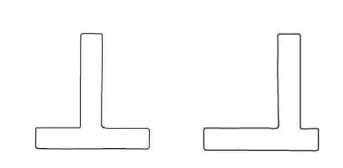
Figure 4-12. The vertical member is positioned in the middle of an equal T section, while it is moved to one side on an offset T section.
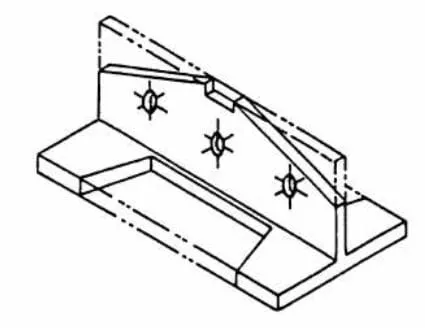
Figure 4-13. An application where either T section may be used.
L Sections. The L-shaped cast section, Figure 4-14, has a right-angle shape and is often used for applications when the bottom portion of a T section might get in the way. As shown, both the vertical and horizontal sides are the same. L sections come in five different sizes ranging from 3.00” x 3.00” to 8.00” x 8.00”, and are available in either 6.00” or 25.00” lengths. The web thickness is proportional to the overall size.
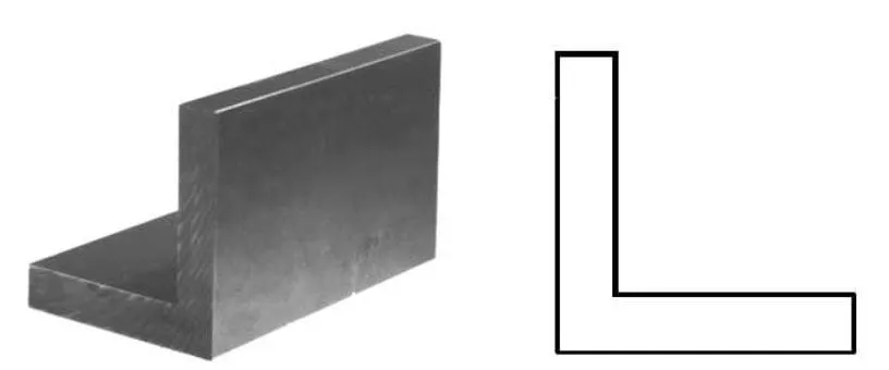
Figure 4-14. The L section.
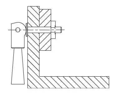
Figure 4-15. A typical fixturing application using an L section.
U Sections . U-shaped cast sections, Figure 4-16, are widely used for channel-type workholders. These sections have a square cross-sectional profile with identical height and width dimensions, as shown. U-sections are available in seven sizes ranging from 1.75” square to 8” square. The web thickness of these sections is, once again, proportional to the overall size. The smaller U sections are made in 19.00” lengths.
The larger sizes are available in full 25.00” lengths. All sizes are available in 6.00” lengths. Figure 4-17 shows two workholders constructed from this type of cast section.
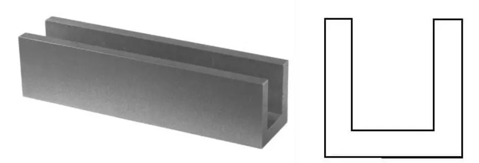
Figure 4-16. The U section.
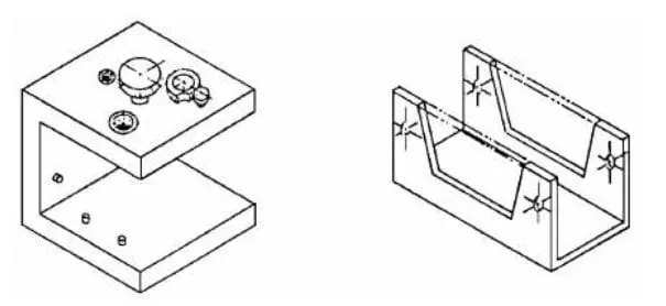
Figure 4-17. Examples of workholders constructed from U sections.
V Sections. V-shaped cast sections, Figure 4-18, are useful when a V-shaped element is needed for either locating or clamping. Thin portions of this material are often used as V pads. Longer lengths are frequently used as V blocks, Figure 4-19. V sections have a rectangular cross section with the width greater than the height. The V-shaped groove is machined to 90º ± 10’. V sections come in three sizes, ranging from 1.00” x 2.00” to 2.50” x 4.00” in standard 6.00” and 18.00” lengths.
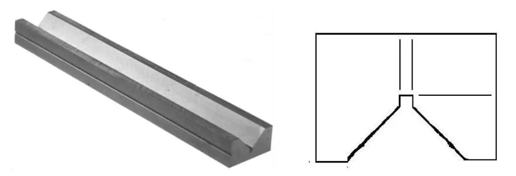
Figure 4-18. The V section.
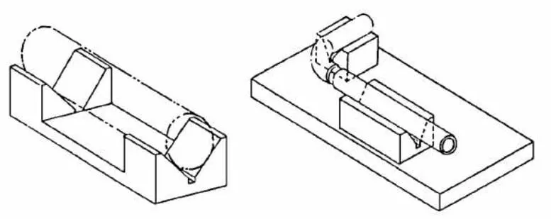
Figure 4-19. V sections are often used as V blocks for locating cylindrical parts.
Square Sections. Square cast sections, Figure 4-20, are typically used as major structural elements.
Applications include riser elements, supports, or four-sided tooling blocks, as shown in Figure 4-21. Square sections are made in four standard sizes from 3.00” square to 8.00” square. Each size is available in either 6.00” or 25.00” lengths. All external surfaces except the ends are precisely machined.
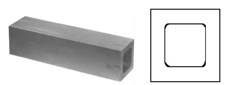
Figure 4-20. The square cast section.
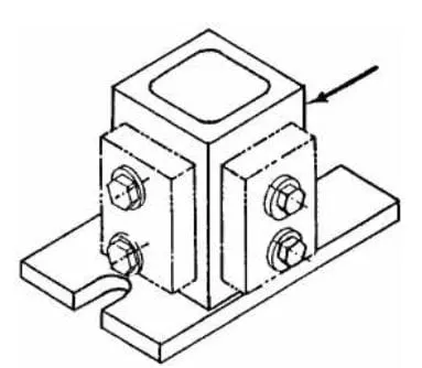
Figure 4-21. A fixturing application with a square cast section used as a tooling block.
Rectangular Sections. Rectangular cast sections, Figure 4-22, like square sections, are often used as structure elements in workholders. These sections work well for base elements, riser blocks, or similar features. Rectangular sections come in three standard sizes from 4.00” x 6.0” to 8.00” x 10.00”. Here, too, all external surfaces except the ends are precisely machined. They are available in 6.00 and 25.00” lengths.
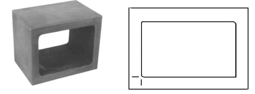
Figure 4-22. The rectangular cast section.
H Sections. H-shaped cast sections, Figure 4-23, are a unique design well suited for either complete tool bodies or structural elements. These sections are basically square and come in five sizes ranging from 3.00” x 3.00” to 8.00” x 8.00”. All H sections are made in 6.00” and 25.00” length. Figure 4-24 shows an application with the H section as a tool body.
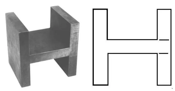
Figure 4-23. The H section.
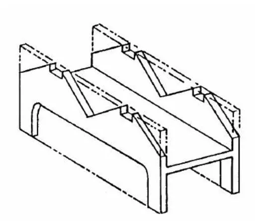
Figure 4-24. A typical application with an H section as a tool body.
Flat Sections. Flat cast sections, Figure 4-25, are the simplest and most-basic type of cast section. These sections are used where a cast iron material is preferred over steel flat stock. Flat sections are available in five width and thickness combinations. The sizes range from .63” x 3.00” to 1.25” x 8.00”, and 6.00” and 25.00”
lengths. Flat sections work well as base elements for smaller jigs or fixtures, or as structural elements for larger workholders.
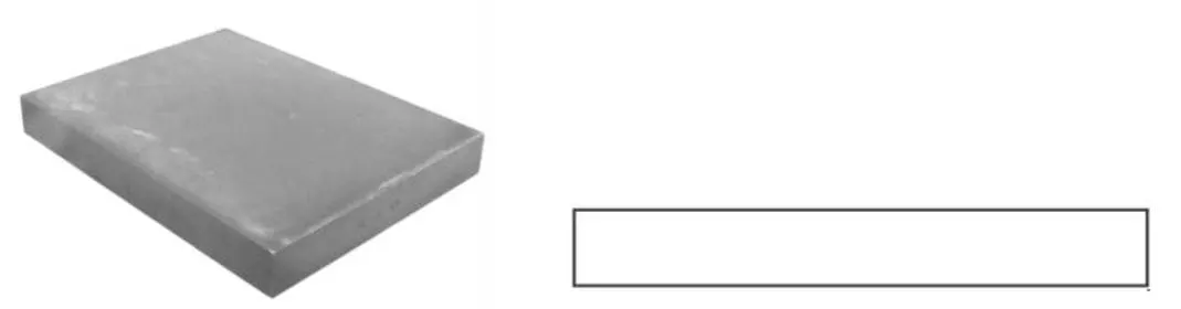
Figure 4-25. The flat cast section.
PRECISION ANGLE BRACKETS
Precision Angle Bracket
Angle brackets are often used when a right-angle alignment or reference is required. Although angle brackets are commonly thought of as 90º elements, there are also adjustable-angle styles of angle brackets and plates.
Plain Angle Brackets. The plain angle bracket, Figure 4-26, is available with or without locating holes.
Angle brackets are often used when a fixed 90º angle is required. The right angle of these plates is closely controlled and is accurate to 90º ± .08º. These brackets are made in ASTM A36 steel or 6061-T6 aluminum.
Angle brackets come in 10 different sizes ranging from 2.00” x 2.50” to 6.00” x 6.00” with both equal and unequal leg lengths. The web thickness of these sections is also proportional to the overall size, ranging from .22” to .44”.
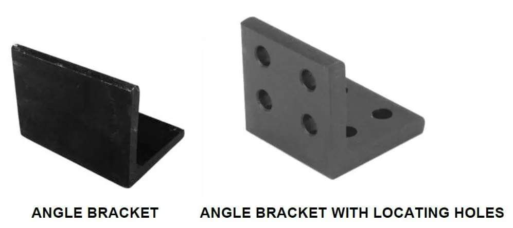
Figure 4-26. Angle brackets are machined flat and parallel to close tolerances. They are also available with precision locating holes for 3-axis accuracy.
Gusseted Angle Brackets
The gusseted angle bracket, Figure 4-27, is a variation of the standard angle bracket. This angle bracket is made with a gusset between the horizontal and vertical legs. The gusset stiffens the angle bracket and reduces any distortion when heavy loads are applied. These angle brackets also have a right angle accurate to 90º ± .08º. These brackets are made in ASTM A36 steel or 6061-T6 aluminum.
Gusseted angle brackets are available in 10 different sizes ranging from 2.00” x 3.00” to 6.00” x 6.00”.
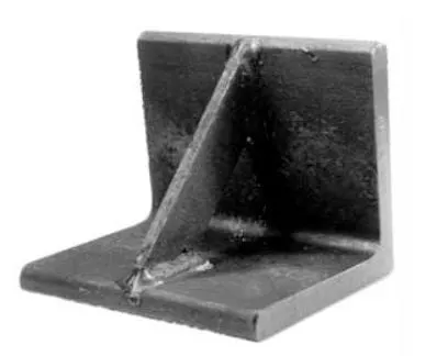
Figure 4-27. Gusseted angle brackets have a gusset for added rigidity and strength.
Adjustable Angle Brackets
Adjustable angle brackets, Figure 4-28, are another variation of the plain angle bracket. These brackets are made with a close-tolerance hinge between the horizontal and vertical legs.
The hinge permits the bracket to pivot so it may be set at any desired angle. The most-basic adjustable angle bracket is the plain type, shown at (a). This type has a bolt and nut arrangement for the hinge. The gusseted adjustable angle bracket, shown at (b), also has a bolt and nut hinge, but it also has a gusset mount on both legs. The mount permits the two legs to be connected with a gusset that is either bolted or welded to the mounts. For applications where the angle bracket must be disassembled, the removable-pin-type adjustable angle can be used. This angle bracket, shown at (c), uses an L pin to attach the horizontal and vertical legs.
These brackets are made of 1018 steel. The plain and gusseted adjustable angle brackets come in three different sizes ranging from 3.00” x 3.00” to 4.00” x 4.00”, with equal or unequal leg lengths. The removable pin type is made in two sizes, 4.00” x 4.00” and 6.00” x 6.00”.
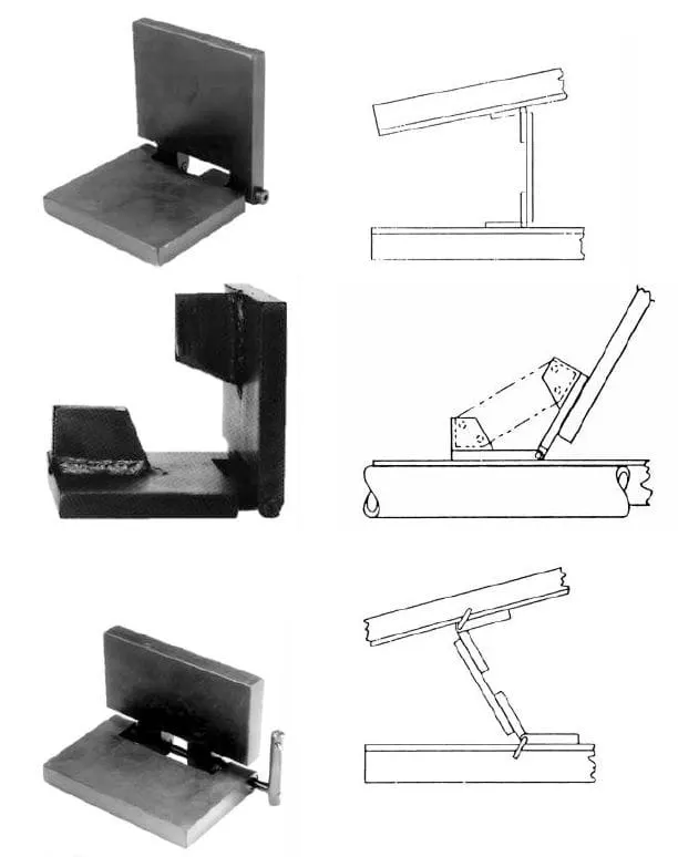
Figure 4-28. Adjustable angle brackets have a close-tolerance hinge for accurate location
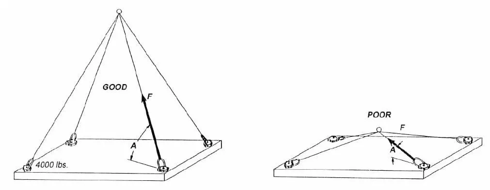
Figure 4-29. The load on a hoist ring is not simply total weight divided by the number of hoist rings. Shallow lift angles can cause very-large resultant forces.
HOIST RINGS
Hoist Rings
Hoist rings should, for safety reasons, be added to any tool weighing over 30 pounds. The following are design considerations when selecting hoist rings.
Hoist-Ring Safety Precautions. Simply following a few basic safety precautions makes working with hoist rings both safer and more efficient.
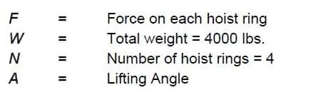
- The load on each hoist ring is not simply total weight divided by the number of hoist rings. The resultant forces can be significantly greater at shallow lift angles and with unevenly distributed loads. In the example shown in Figure 4-30:
- Despite the 5:1 safety factor on hoist rings, never exceed the rated load capacity. This safety margin is needed in case of misuse, which could drastically lower load capacity.
- Tensile strength of fixture-plate material should be above 80,000 psi to achieve full load rating. For weaker material, consider through-hole mounting with a nut and washer on the other side.
- Do not allow hoist rings to bind. Use a spreader bar, Figure 4-30, if necessary, to avoid binding.
- Do not use spacers between the hoist ring and the mounting surface.
- Do not apply shock loads. Always lift gradually. Repeat magnaflux testing if shock loading ever occurs.
- Never lift with a hook or other device that could deform the lifting ring. Use only cable designed for lifting.
- Tighten mounting screws to the torque recommended. Because screws can loosen in extended service, periodically check torque. For hoist rings not furnished with screws, mount only with high-quality socket-head cap screws.
- The mounting surface must be flat and smooth for full contact under the hoist ring. Tapped mounting holes must be perpendicular to the mounting surface.
After installation, check that rings rotate and pivot freely in all directions
Standard Hoist Rings. Standard hoist rings, Figure 4-31, have a low profile and are attached directly to the mounting surface with socket-head cap screws. This is the most economical type of hoist ring. The solid forged lifting ring pivots 180º but does not rotate. These hoist rings are available for loads to 20,000 lbs.
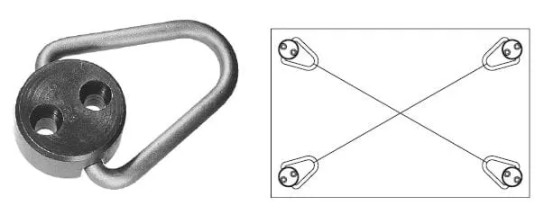
Figure 4-31. Standard hoist rings have a forged ring that pivots 180º.
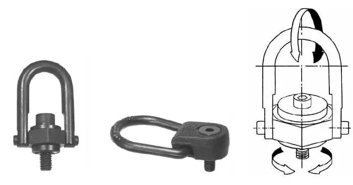
Figure 4-32. Swivel hoist rings pivot 180º and rotate 360º simultaneously to allow lifting from any direction.
Swivel Hoist Rings. Swivel hoist rings, Figure 4-32, are a form of hoist ring with a 180º pivot and 360º rotation. These hoist rings, available in the two variations shown, are mounted with a single screw. As shown in Figure 4-33, these hoist rings are always preferred over conventional eye bolts or forged lifting eyes when side loads are expected. The pivot-and-swivel combination permits the hoist ring to accommodate lifting angles that can cause a standard eye bolt or forged lifting eye to break. An inherent advantage of the swivel hoist ring when compared to the eyebolt or lifting eye is the ability of the swivel hoist ring to swivel, rather than being fixed in one orientation. Forged lifting eyes and eyebolts have their maximum lifting strength when the axis of the eye is perpendicular to the lifting angle, and when the lifting eye is screwed all the way to the shoulder. It is very difficult to achieve both of these conditions simultaneously. The swivel hoist ring solves those problems easily. These swivel hoist rings are available for loads up to 10,000 lbs. They are available in a wide variety of sizes with either black oxide or electro-less nickel plate finish, and many are available in stainless steel.
A useful hoist-ring accessory is the hoist-ring clip, shown in Figure 4-34. These clips keep the swivel hoist rings stationery and out of the way when they are not being used for lifting.
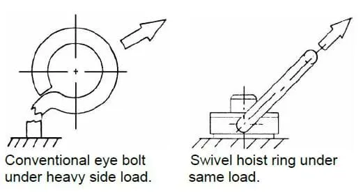
Figure 4-33. Hoist Rings should be used in place of eye bolts for all heavy lifting applications.
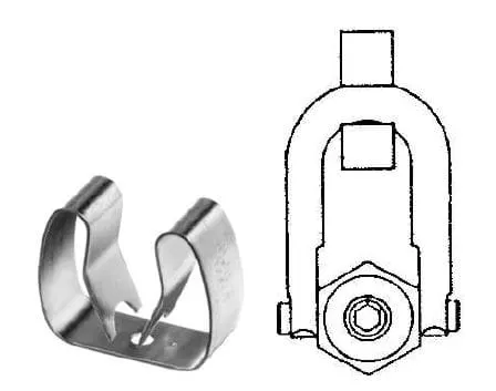
Figure 4-34. Hoist-ring clips keep swivel hoist rings stationary while not in use for lifting.
Other styles of hoist rings are also commercially available. These styles including Heavy-Duty Swivel Hoist Rings, Heavy-Duty Weld Mount Swivel Hoist Rings, and Shackle Hoist Rings. Figure 4-35.
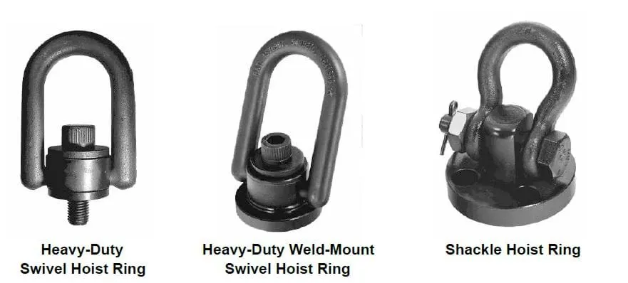
Figure 4-35. Three additional types of swivel hoist rings.
Heavy-Duty Swivel Hoist Rings have a forged steel ring, which pivots 180 degrees and swivels 360 degrees simultaneously to allow lifting from any direction. They have a maximum lifting capacity of 30,000 pounds.
Heavy-Duty Weld Mount Swivel Hoist Rings are, as the name implies, attached by welding, and are available in capacities up to 24,000 pounds. Shackle Hoist Rings are designed for permanent mounting on tooling and equipment. It can be bolted or welded in place. Each of these hoist rings can pivot 180 degrees and swivel 360 degrees simultaneously to allow lifting from any direction. All have a safety factor of 5:1.
Lifting Pins. Lifting pins, Figure 4-36, are a modified form of hoist ring. Sizes are available for loads up to 3,400 lbs. These pins have a positive-locking four-ball arrangement to hold them in place during lifting. A release button at the opposite end of the pin allows quick installation and removal. Figure 4-37 shows two typical applications. These pins are made of 17-4Ph stainless steel.
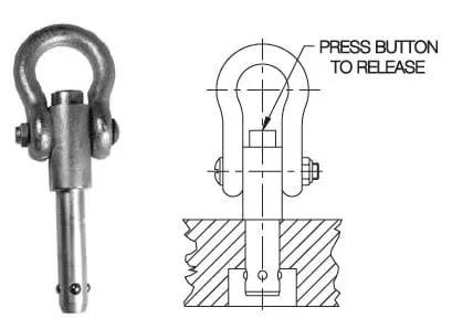
Figure 4-36. Lifting pins are medium-duty hoist rings that can easily be completely removed
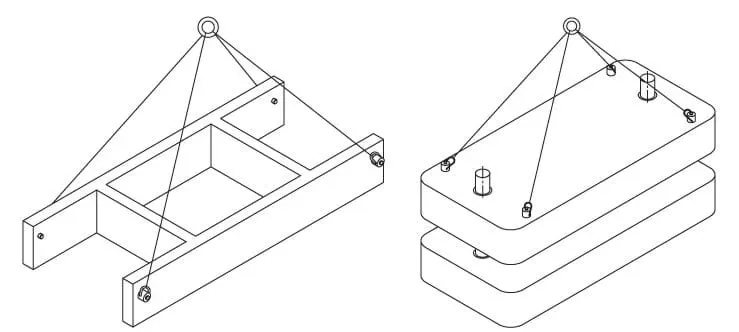
Figure 4-37. Typical applications for lifting pins.
Threaded Inserts
Threaded inserts are widely used for construction and repair of workholders. The most common use for the inserts is to reinforce threads in new workholders or to repair threads in existing workholders. Threaded inserts provide a way to strengthen threaded holes in new workholders where repeated use may cause excessive wear, such as with aluminum or other soft fixture plates. With existing jigs and fixtures, threaded inserts are a quick way to fix stripped, damaged, or worn threads. Two primary forms of threaded inserts are Keenserts and self-tapping threaded inserts.
Keenserts, Figure 4-38, are threaded inserts for both repairing and reinforcing applications. The Keensert design uses a standard tap size for installing the insert. This feature eliminates the cost of special taps for threading the mounting holes. As shown, the inserts have unique locking keys that both securely hold the inserts in place and prevent rotational movement. The method of installing these inserts is shown in Figure 4-39.
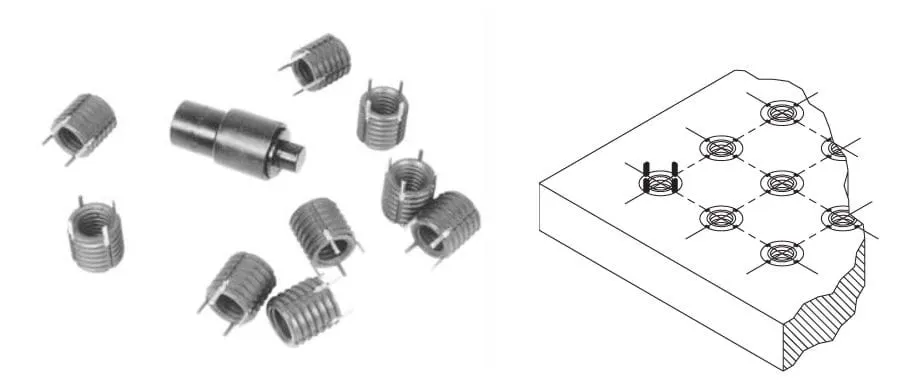
Figure 4-38. Keensert threaded inserts are frequently used to reinforce threads in soft tooling plates.
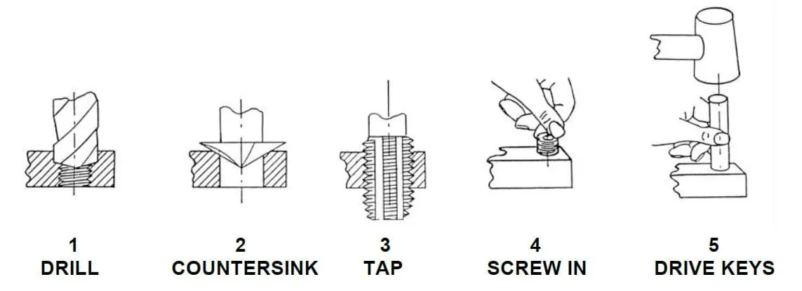
Figure 4-39. Installation steps for Keensert threaded inserts.
- Drill out the old thread, if repairing an existing thread, or drill a new hole to the specified tap drill diameter (slightly larger than the normal tap drill for that thread size).
- Countersink the entry end of the hole to the specified diameter.
- Tap the new threads to the correct size with a standard tap.
- Screw in the insert until the body is slightly (.010” to .030”) below the surface. The locking keys act as a depth stop.
- Drive the keys down with several light hammer taps on the installation tool (or directly on the keys).
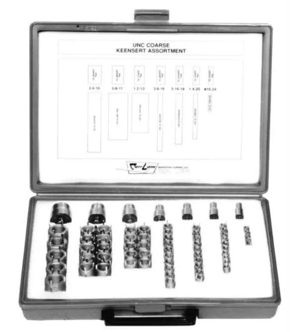
Figure 4-40. Standard Keensert assortments contain many different insert sizes and a tool for each size.
Keenserts are made in a variety of forms for almost any application. The inserts are available in a heavy-duty carbon-steel style in standard inch sizes from #10 through 1 ½, and in metric sizes from M5 to M20. Stainless steel, heavy-duty, and thinwall inserts are also available in either plain or internal-thread-locking styles. A variety of standard Keensert assortments are also available for UNC, UNF and metric threads, Figure 4-40.
One other style of Keensert, ideal for repair work, is the solid Keensert, Figure 4-41. As shown, these stainless steel inserts are typically used for relocating tapped or drilled holes. They come with external-threaded diameters from 5/16” to 1 3/8”.
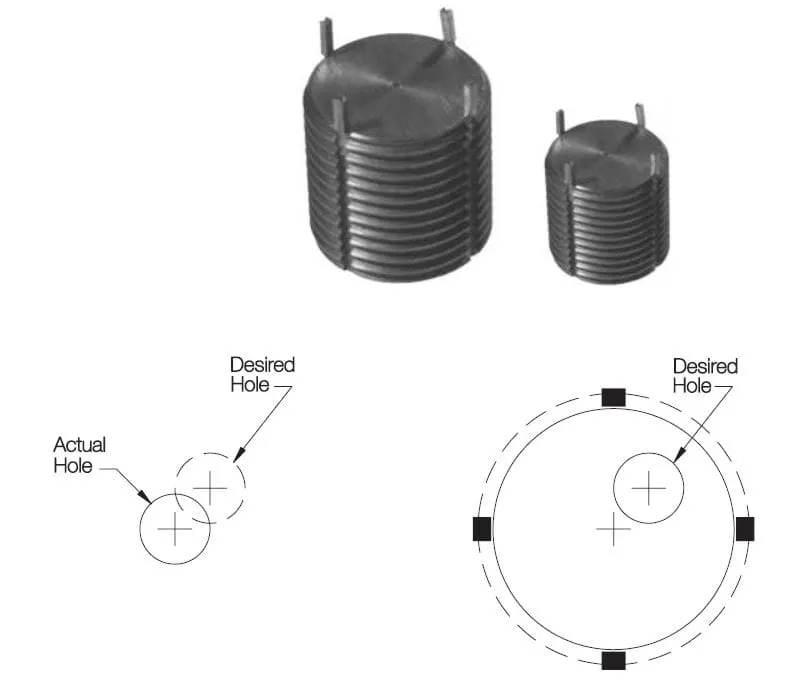
Figure 4-41. Solid Keenserts are handy plugs for relocating misplaced holes.
Fixture Keys
An accurate relationship between the workholder and the machine tool must be established. Fixture keys not only establish location initially, they also help hold the fixture in place during machining.
The two basic styles of fixture keys are the slot-mounted and hole-mounted types. Slot-mounted fixture keys are made in two variations, the plain fixture key and the step fixture key, Figure 4-42. The plain fixture key, shown at (a), is the simplest and least expensive of the slot-mounted keys. As shown, these keys are mounted in a slot cut to a depth equal to half the thickness of the key. The key is held in place with a socket-head cap screw.
The second style of slot-mounted fixture key is the step key, shown at (b). These fixture keys are a variation of the standard fixture key. This key’s step design allows a fixture with one slot width to work on a machine table with a different slot width. Like the plain-style key, this key is held in place with a socket-head cap screw.
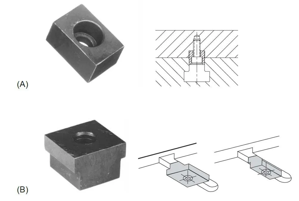
Fixture 4-42. Plain fixture keys and step fixture keys.
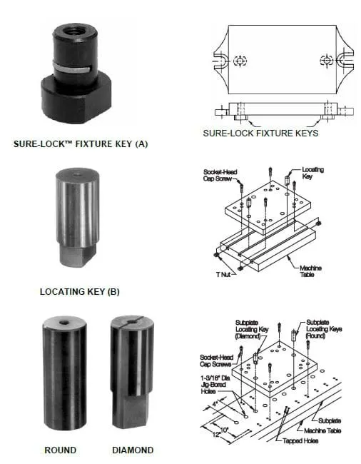
Fixture 4-43. Sure-Lock™ fixture keys are ideal for small and medium fixtures, while removable locating keys are best for large, heavy fixtures. Subplate locating keys allow mounting the same fixtures on a subplate with 3-axis location.
Hole-mounted fixture keys are also made in several variations. The most popular are the Sure-Lock™ fixture key and the removable locating key, Figure 4-43. Hole-mounted keys eliminate the need to slot fixtures. The Sure-Lock™ fixture key, shown at (a), is the most popular of all fixture keys. Keys for any machine-table slot mount in a .6250” reamed hole for interchangeability. This design has a unique locking arrangement to precisely align and lock the fixture key in the hole. As shown, Sure-Lock™ fixture keys can be secured from either the top or bottom of the fixture. These keys are made in many sizes, for all standard USA table slots from 3/8” to 13/16”, and metric table slots from 12mm to 22mm.
Locating keys, shown at (b), are the standard removable-type fixture key for large, heavy fixtures. These keys can be inserted from above after placing the fixture on the machine table, and then removed again if desired after the fixture is fastened. This design keeps the fixture’s bottom side free of obstructions. Locating keys all mount in a 1.1875” reamed hole. They are available in many sizes, for all standard USA table slots from 9/16” to 7/8”, and metric table slots from 14mm to 22mm.
Subplate locating keys, shown at (c), are designed for mounting quick-change fixture plates on a subplate. A round key and a diamond (relieved) key are used together for precise location without binding. Two standard diameters, .6250” and 1.1875”, match standard fixture-key holes. This allows mounting these same fixture plates either on a subplate (3-axis location) or directly on a machine table (2-axis location).
Pallet Fixture Keys. Fixture keys for mounting tooling plates and blocks on standard DIN pallets. Each pallet requires one center key and one radial key (for orientation). If desired, the radial key can be removed after fastening the pallet to the machine table. A tapped hole in the top of each pin makes insertion and removal easier. Center keys are available for 25, 30, and 50mm holes. Radial keys are available for 20 and 25mm holes. See Figure 4-44.
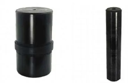
Figure 4-44. Two pallet fixture keys, one for center location and one for radial orientation, are used for DIN mounting on horizontal machining centers.
JIG CONSTRUCTION
Jigs are made to meet the requirements and specifications of individual workpieces, resulting in an infinite number of different jigs. Even though every jig may be different, each can be grouped into one of only a few categories. The following is a description of the basic jigs and the applications where each is best.
Template Jigs
Template jigs, Figure 4-45, are the simplest and least-expensive jigs. They are generally used for layout or light machining. They are designed for accuracy rather than speed. Template jigs do not have a self-contained clamping device. If a clamp is needed, a secondary clamp such as toggle piers may hold the jig to the workpiece. When a template jig is used for drilling multiple holes, a pin placed in the first drilled hole can reference the jig.
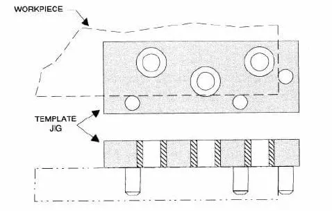
Figure 4-45. Template jigs are simple plates usually held in place by hand.
Plate Jigs
Plate jigs are very similar in their basic construction to template jigs. As shown in Figure 4-46, plate jigs have a self-contained clamping device. Although many different clamps can be used, a screw clamp is the most-common type with these jigs.
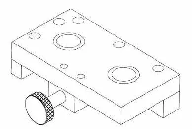
Figure 4-46. Plate jigs are similar to template jigs, except they include a clamp.
Table Jigs
Table jigs are a variation of the basic template or plate jig. The table jig shown in Figure 4-47 is basically a template jig installed on legs. Table jigs are designed for applications where the surface to be machined also locates the workpiece. The location is transferred across the underside of the jig plate and down the legs to the machine table. When designing this type of jig, make sure the area to be drilled is inside the legs to prevent tipping. Although three legs will work, four are recommended with table jigs. Four legs also wobble if a chip is under one leg; three legs do not. The wobble tells the operator to clear the chips from the locating surfaces.
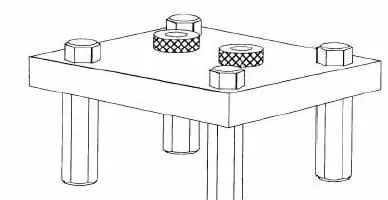
Figure 4-47. Table jigs are basically template or plate jigs raised up on legs.
Indexing Jigs
Indexing jigs are for applications where holes must be drilled in a pattern around a center axis. This is done either with an indexing ring holding bushings, or by indexing the part itself. With a separate indexing ring, Figure 4-48, a hand-retractable plunger is frequently used. A ball-plunger can also be used for less critical positioning. Here the work piece itself serves as the indexing ring. With this design, the first hole is drilled and the part rotated to engage the ball-plunger, Figure 4-49. Once located, the part is re-clamped and a second hole is drilled. The indexing is then repeated until all the holes in the part are drilled. The angular position of the ball plunger relative to the drill determines the indexing pattern. So, for four holes, the plunger is located at 90º from the drill, 60º for six holes, 45º for eight holes, and so on.
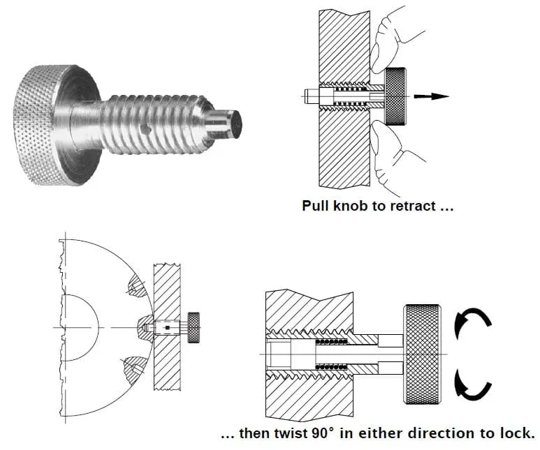
Figure 4-48. A hand-retractable plunger can be used to positively index a ring holding drill bushing.
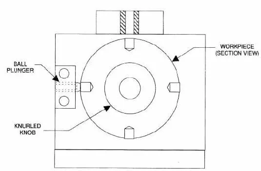
Figure 4-49. A ball-plunger can index using holes drilled in the workpiece.
Index Plungers
Index plungers are heavier-duty spring-loaded locators. Precision bushings are available to fit the plungers.
They are available in a choice of mounting styles, and with either tapered or straight plungers.
Multi-station Jigs
Multi-station jigs, Figure 4-50, are for repetitive simultaneous operations on several identical parts. In most cases, almost any jig may be used with a multi-station arrangement. As shown, the unique feature of a multi-station jig is the way the jigs are mounted and arranged with respect to the machining stations. In this example, the jig has four stations: #1 is the load/unload station; #2 is for drilling; #3 is the reaming station; and #4 is where the workpiece is counterbored. An indexing arrangement is also included with this jig to accurately position the jigs at each station.
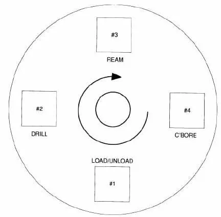
Figure 4-50. Multi-station jigs are used in a continuous, multi-step production process.
Trunnion Jigs
Trunnion jigs, Figure 4-51, are for large, heavy, or odd-shaped workpieces. This type of jig rotates the workpiece on precision bearing mounts called trunnions. Trunnions are made it two basic styles: standard and spherical.
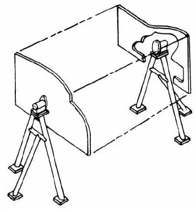
Figure 4-51. Trunnion jigs allow easily turning a large part to work on all sides.
Standard trunnions, Figure 4-52, are available in either locking or revolving styles. With most trunnion jigs, trunnions are typically used in pairs: the revolving trunnion provides a rotating pivot, and the locking trunnion both rotates and locks at any rotational angle. Locking trunnions are locked in place with a friction-cone arrangement engaged by turning the locking handle. Trunnions are intended for low speed rotation, such as when repositioning a fixture to allow proper access to complete a weld.
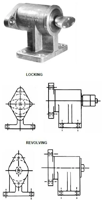
Figure 4-52. Trunnions are usually used in pairs, one locking and one revolving.
These trunnions come in two size ranges, small, with a weight limit of 1,500 pounds at a distance of 18 inches from the face, and the larger one, with a weight limit of 2,500 pounds 18 inches out from the face. In pairs, either the weight limit, or the distance can be doubled, but not both. For larger fixtures, either longer or heavier, exceeding these limits will lead to premature failure of the trunnion(s).
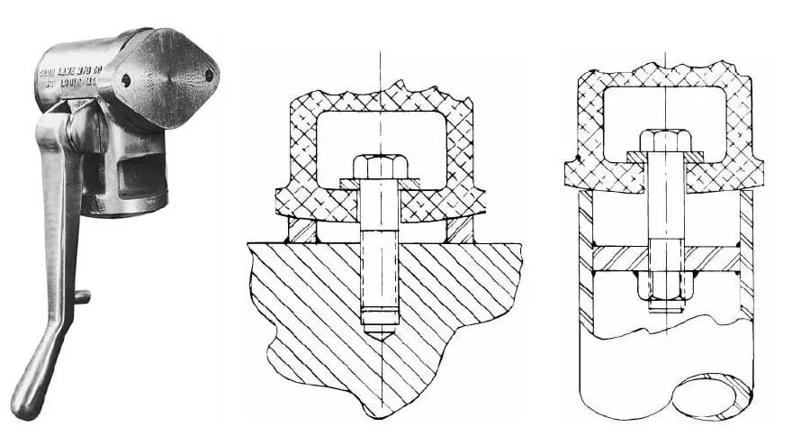
Figure 4-53. Spherical trunnions are ideal for mounting on pipe frames.
Spherical trunnions, Figure 4-53, are a locking trunnion for pipeframe mounting. The spherical bottom aids in precisely aligning the trunnions. Spherical trunnions lock the jig in position by lowering the handle.
FIXTURE CONSTRUCTION
Fixtures, like jigs, can be grouped into a few categories. These categories are most often based on the construction of the fixture. Another way to identify a fixture is by the machine it is used with.
Plate Fixtures
The plate fixture is the most basic and most common fixture. The plate fixture is built with a Carr Lock® Fixture Plate, cast flat section, tooling plate, or similar plate material. All locators, supports, and clamps are mounted directly to the plate. As shown in Figure 4-54, a complete plate fixture can be built using on standard, off-the-shelf components.
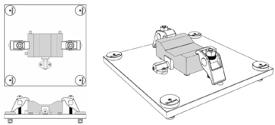
Figure 4-54. Plate fixtures usually hold a workpiece parallel to the machine table.
Angle-Plate Fixtures
Angle-plate fixtures are a variation of the basic plate fixture. They are useful when the locating surface is at an angle to the machine table. The two main variations of angle-plate fixtures are the right-angle and modified-angle plate fixtures. Right-angle plate fixtures, Figure 4-55, are constructed at 90º to the base. The modified-angle plate fixtures have an angle other than 90º. The right-angle plate fixtures can be built with tooling blocks, T cast sections, L cast sections, angle brackets, or any comparable material. Adjustable angles or sine plates may be used to build the modified-angle plate fixtures.
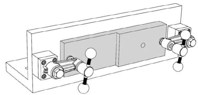
Figure 4-55. Angle-plate fixtures usually hold a workpiece perpendicular to the machine table.
Welding Fixtures
All basic workholding principles should be applied to fixtures used for welding operations. The major differences between most welding fixtures and machining fixtures are the locational tolerances and clamping methods. With welding fixtures, weight is often a problem. Many times a fixture is made up of welded sections.
The sections are usually positioned only in the areas where the parts to be joined contact the fixture. Rather than the precision locators found on most machining fixtures, small angle clips, blocs, or similar elements are used as locators.
The clamps for welding fixtures are often toggle clamps. These clamps offer the best combination of design flexibility, holding capacity, and operational speed. In addition, since most toggle clamps move completely clear of the work area when opened, loading and unloading operations are also simplified. Although the clamps may be attached with a screw, in many instances toggle clamps are welded directly to the fixture body.
A few important considerations to keep in mind when building a welding fixture are as follows:
- Always construct the fixture so that the parts to be welded can be loaded only in the correct orientation.
- Supports are needed underneath clamps to prevent distortion.
- Locators and supports must be positioned so any workpiece distortion caused by welding heat loosens, rather than tightens, the workpiece in the fixture.
- Only essential dimensions and relationships should be located and rigidly clamped.
- All areas to be welded must be easily accessible.
- When possible, welding should be done on a flat, horizontal plane.
- To minimize warping of the workpiece, provisions to dissipate excess heat must be included in the design.
- As many operations as possible should be performed before the workpiece is removed or repositioned.
- Large or heavy loads should be completely supported, and provisions for lifting the jig with a hoist must be included.
Lifting Columns
The manipulation of odd shaped, heavy, and/or bulky items for welding, inspection, or assembly can lead to operator fatigue, mistakes and injuries. Manual/hydraulic lifting columns can eliminate these conditions while simplifying the performance of these tasks. Available in lifting capacities from 225 to 1,350 pounds, these columns are easily raised or lowered by pumping a foot pedal, or releasing pressure to position the work at the optimum level for ease and accuracy. See Figure 4-56.
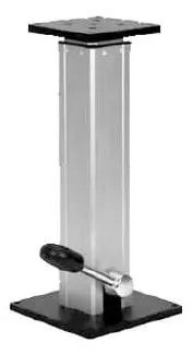
Figure 4-56. Lifting columns are used to easily raise and lower a fixture for convenient access.
Rotating modules are also available for these columns to allow rotation of the workpiece in either the horizontal or vertical axis. They are available as free rotating modules, or with locks operated either by hand or foot pedal. See Figure 4-57.
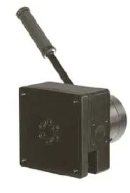
Figure 4-57. Rotating modules allow easily turning a large fixture for convenient access.
Inspection Fixtures
Inspection and gaging fixtures are subject to different requirements than machining fixtures, whether inspection is done on a CMM (Coordinate Measuring Machine) or with manual gages. The following are key differences and unique aspects of inspection fixtures:
- The workpiece must be oriented to expose all features to be inspected.
- Machined surfaces are often not used for locating, to allow them to remain exposed.
- Bridge-type CMMs require different tooling than horizontal-arm machines.
- Since most CMMs can automatically reference a part to the machine, often only approximate orientation in the fixture is required.
- Quick-acting clamps, such as toggle clamps, are widely used in inspection fixtures due to the light clamping forces usually required.
- Inspection fixtures can be either permanent or modular.
TYPES OF WELDING FIXTURES
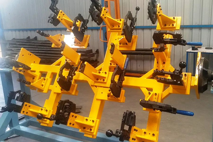
The main purpose of a fixture is to locate, support and hold the workpiece in position firmly to obtain a precise product from a process.
A welding fixture is designed in a way to support and locate the components to be welded to avoid distortions and weld stresses. It is obvious that each welding operation requires a distinct welding fixture according to our desired requirements. A fixture generally holds the part during welding, but there is a chance of the part being distorted after the removal of the fixture. Hence some stress-relieving and other post-processing operations can be performed to prevent weld distortions.
1. Gas Welding Fixtures
Welding is done by burning fuel in the presence of oxygen which produces extremely high temperatures that melt the parts and join them during welding. In the case of gas welding, the heat loss should be minimum to avoid weld cracks. Hence fixtures should be designed in such a way that large fixture masses are located away from the weld line while providing enough support to the workpieces.
Special care is required while welding copper and aluminium due to excessive heat loss from the materials. To address this difficulty, tack welding has to be done on the points away from the fixture contact points and the rest of the welding is done out of fixtures. C-clamps and hold down plates are additionally used to support the workpiece and prevent weld distortions.
2. Arc Welding Fixtures
The workpiece can react chemically with oxygen and nitrogen gases from the air at higher temperatures produced by the arc while welding. To prevent the part from reacting with air, a protective shielding gas is used around the welding area to minimise the exposure of the workpiece to the surroundings.
The temperatures produced in arc welding are much higher than those in gas welding. Hence they are used in welding steel structures and vehicles. More heat is generated at the weld line in arc welding than that of gas welding. Therefore the fixture, in this case, should provide good support, proper alignment to the workpiece and also allow heat dissipation from the weld area.
They should provide enough force to align the workpiece firmly. This force is applied at suitable points by clamps supported by backing bars. These backing bars not only provide robust support to the molten metal but also shield them from distortion.
3. Resistance Welding Fixtures
The fixtures must be free of debris and flash for safe operation. There are various reasons for healing up of the fixture like inductance, insulation, weld flash and location. Even magnetic tooling causes similar issues. The tool absorbs energy and heats up during welding which forces the welder to work harder for spot welding. To avoid this, fixtures, base plates and other components are made from non-magnetic materials.
Insulate fixture to prevent current flowing through it and heating up due to resistance heating. From bolts to mating surfaces, insulate all the components of the fixture.
4. Laser Welding Fixtures
Laser welding is known for its versatility and quickness in producing narrow, deep welds with a minimum distortion and heat input. It has gained much popularity among the parts that require little to no-post weld processing. Also, laser welding with a proper fixture eases the tool work, results in a precise product in less time.
A high-intensity laser beam is focused on the part to be welded using a lens. It melts the material and fusion welding takes place due to the intense heat produced. The fixture should be designed such that the laser is placed on a firm mounting to prevent vibration.
Sufficient space is allowed between work table and lens to in-house various positioning tools. When more than one fixture has to be used, control the working heights of both the fixtures with respect to each other to prevent accidental defocusing that may result in poor quality.
In a word, a fixture is the one that makes work easier for tools, reduces lead time, improves productivity and quality of the welded parts without any distortion. A different fixture is designed for different welding operations. There are Robotic welding fixtures to perform automatic welding, BIW welding fixtures, Lift and Weld fixtures, frame fixtures, railing weld fixtures etc each one with each purpose. We shall go through each of them in the upcoming articles.
-
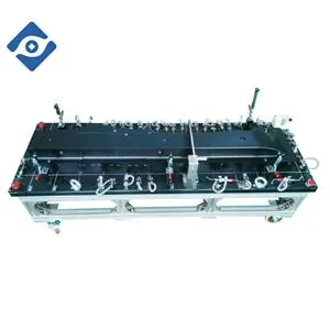
Checking Fixture for REINF FRT VLC PNL
Gauge type:checking fixture for metal part Inspection type: hole position, hole size, surface profile and trim edge,flatness check,CMM inspection.
OK-VISE® Method of Automated Clamping
As the original inventor of the wedge-operated low-profile clamp, OK-VISE has introduced hydraulic actuators that are optimized to utilize the well-known properties of the OK-VISE clamp: extreme clamping force in a small space combined with the accuracy of the clamping force. As an integral part of the OK-VISE Fixturing Concept, hydraulic actuators can be used to build truly modular fixtures.Hydraulic clamping can used in combination with- Automated or manual workpiece loading
- Vertical or horizontal machining centers and 5-axis machines
- Live systems (continuous pressure supply) or decoupled system
OK-VISE is continuously developing new automated modules for robotic loading, and also for manually operated systems where automation saves operator’s loading time and improves ergonomics.
Clamping concept
Part will be clamped with automatic move clamps, all toggle joint clamps fitted with hand lever.
The fixture should be opened automatically after welding cycle.
In robot section / welding side it should be possible to move the clamps or clamper groups with the
HMI.
For safety in loading side (worker area) the clamps and pistons are depressurized when the safety
area is not empty. Only secured movements for position pins on separate valves can be under
pressure.
If more than one (1) operator load / unload the fixture the safety concept must be designed in such a
way that the risk of injury the operators is avoided.
Clamp sensors are required for both Open and Close positions on all tools. JCI/AME approve is
required if there is an exception required due to application specific issues.
Slides require cylinders sensors for both positions.
All fixture clamps must clamp down on the parts to consistently locate the parts and this must include
clamp backup details based on the application. Clamp backups must be located near the clamping
area so that the part does not rock, deflect, or become loose once clamped together.
Note 1 – Some areas that may not have Clamp Backup
Details: If the part itself cannot handle the clamp pressure, clamps must be supported by a backup
detail so that the part being welded is repeatable and stable for the welding process.
Note 2 – Clamps with Backup
Details: If the area already has 1, 2 or 3 other clamps with backup details, not every clamp has to have
its own backup. The goal is to consistently locate the parts and not bend, deflect, or move the parts
once clamped up together in the fixture.
** Have the AME Sign off on all tooling reviews before building the tools!-
Checking Fixture for REINF FRT VLC PNL
Gauge type:checking fixture for metal part Inspection type: hole position, hole size, surface profile and trim edge,flatness check,CMM inspection.
Clamps and Accessories
OK-VISE® is a well-recognized international trademark, best known as an original inventor and manufacturer of the wedge-operated Low-profile Clamps. Today our Fixturing Concept includes several systems, which enable customers to build fixturing with ease never previously experienced.
OK-VISE® products are used in workholding, especially in fixtures used in machining centers and milling machines. With OK-VISE components a variety of workpiece types, sizes and materials can be securely held on all possible workholding platforms.
Minimum piston/cylinder diameter 40
Piston sensors are required for both Open and Close
positions on all tools.
JCI/AME approve is required if there is an exception
required due to application specific issues
Piston sensors must be visible installed for the worker
Preferred working position of piston that the piston rod is inside of piston. When it’s not possible the
piston rod must be protected against weld spatter
Piston guidance
For piston that make important or accurate position the execution has to be done with piston guidance
Slide bearing guidance in tolerance according DIN ISO 286 H7/h6
Guidance length min. 2x piston rod diameter
Bearing Material: ISO 2.1090 DIN 1705 (CuSn7ZnPb)
Special Piston solution
Example: Festo DFM Piston with adjustable end stop outside solution
Different brands see released component list
Example: Festo DFM Piston with end stop, hand actuated
Different brands see released component list
Example: Festo Piston ADVU-40-15-P-A-S2, hand actuated with guidance
Different brands see released component list
Guidance and guidance rails
If slides or rails are used to move/shuttle fixture details, ground path must not be through the bearings
and must have ground straps around the slide system.
If slides or rails are used to move/shuttle fixture details, spatter/dirt guards must be part of the design,
by the tooling supplier, so the bearings and end stops are kept clean. The cover will be easy to
dismantle designed.
All slides must be shot pinned for final position verification.
All slides must have bore diameters at least 8 mm or greater. The goal is to make sure the slide has a
greater force than clamps or other details that might be pushing against it.
All Guidance / guide rails have a fixed hardened, adjustable end stop in both slide directions.
Use minimum two parallel working slides with min. three guiding wagon per slide unit.
The guide rail system has to be designed with master rail (longer rail) and slave rail (shorter rail).
Guide wagons have to be fixed with hardened pins on the parts.
Guidance / guide rails that make important positions have to be locked in working position with a
piston, example see picture below.
Spring loaded pressure pieces
When necessary use spring loaded
pressure pieces size M8
Ganter or Drabber
Different brands see released componen
Shim block systems / part placement
Shim block systems for position pins
All fixture details must have 5mm shims to make the position of the detail at the nominal part location
in the X, Y and Z directions. (Fixture must have shimming capabilities in X, Y, and Z).
Examples:
Shim block system for Z surface position
All part surface blocks must be shimable in z according to drawing or according to function.
Examples:Shim block system for tube position
Different solution for tube positioning possible solution.
Position for tube position in V-block, shim in Z, for X adjustment separate plate needed possible.Position for tube position in V-block, shim in Z and X possible.OK-VISE®
Low-Profile clampsSmall in Size – Giant in Performance
Olli Kytölä’s original invention is still the core of our product range. This unique workholding solution is designed to meet the demands of the modern metalworking, plastics, aerospace and electronics industries.
Position for tube position in shim block, shim in Z and X possible.
Clamps & Accessories
Carr Lane Mfg. industrial clamps lead the way in dependability, precision and versatility, offering solutions for all your clamping needs. Carr Lane Mfg. hold down clamps are built in a variety of sizes to provide varying maximum clamping forces to provide a tailored solution for your application. Carr Lane Mfg.'s line of industrial clamps & accessories includes clamp straps, edge clamps, swing clamps, internal clamps, and portable clamps , with accessories including nuts, washers, cams, studs, bolts, nuts, clamp rests, hand tools and more. Browse the complete line of clamps and accessories from Carr Lane Mfg. below.
About Industrial Clamps
Select a Product Line
Shim package in zero CAD design position
o JCI standard base block: 5 mm in package 0,1mm, 0,25mm, 0,5mm, 1mm.
o Surface blocks: 5 mm in package 0,1mm 0,25mm, 0,5mm, 1mm
o Other positioning parts: 5 mm in package 0,1mm, 0,25mm, 0,5mm, 1mm.
Shim design
o All shim plates have to be burr free
o At least required available thickness: 0,1mm 0,2mm 0,3mm 0,5mm 1,0mm 2,0mm 3,0mm
5,0mm
o NA: 0,1mm and 0,2mm no valid, NA: use 0,25mm as smallest sizeExample shim for Destaco toggle clamp
Flat washer / shim ring
o All washers have to be burr free
o At least required available thickness: 0,1mm 0,2mm 0,3mm 0,5mm 1,0mm 2,0mm 3,0mm
5,0mm.
o NA: 0,1mm and 0,2mm no valid, NA: use 0,25mm as smallest size
o With each fixture the supplier has to deliver a set of shims and a set of washers / shim rings
in separate boxes, see figure below.
o Minimum quantity of each shim:
o 15 pcs per used size 0.1mm up to 1mm
o 5 pcs per used size 2mm up to 5mm
o Minimum quantity of each shim ring: 10 pcs per size 0.1mm up to 1mm
In North America Douglas Stamping Company Shim’s must be utilized:
When tooling supplier has completed with fixture installation and pre- acceptance, a shim map
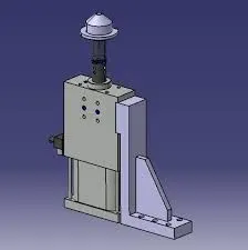
must be provided before approval by JCI.Pin Unit Design
11 Material rules
Part surface / material
All fixture details, which are used to hold parts in place, that have a weld that is 30mm or closer to the
fixture, details must be Ampco 21®, Elkonite® or Elmedur X®. Also any details that hold a part, which
has a weld located on top of the fixture Detail, must also be Ampco 21®, Elkonite® or Elmedur X®.
All fixture details which come in contact with component parts, must be hardened to 52 RC minimum.
Ampco®, Elkonite® or Elmedur® details are required in high weld spatter areas. A2 tool steel is required
for hardened details.
All Fixture-Clamp details that are 30mm or closer to the weld joint must be Elkonite ® or Elmedur X ®
details. JCI AME have to give approval for AMCO ® material to be used based on the specific
application.
Welding spatter sustained metal parts or pins have to be laminated /cladded; TIN (Titannitrid), decide
in design meetings which area will be sustained.
Using normal copper materials is forbidden for positioning parts.
All fixtures parts have to be protected against corrosion with painting, black oxide finish or galvanizing.
Reference elements surface roughness will be
Material information:
Ampco 21® (Aluminium - Bronze alloy): www.ampcometal.com Ampcoloy 940 welding electrodes
material, EU use current Ampco 21
Elkonite ® (Tungsten- Copper alloy): www.tuffaloy.com
Elmedur X ® (Copper alloy - CuCr1Zr - A 2/2): www.thyssenduro.com
Cover / welding spatter protection
The fixture design must include protection guards against weld spatter. Weld fixtures that include weld
parts with spatter free zones must have spatter guards that completely cover and protect the spatter
free zone during welding as called out on the part drawing.
More or different areas can be defined from AME out of his experience in design phase without any
extra charge.
For part applications with no spatter zones on part areas, weld nuts, holes, or other features, guards
must be made of appropriate materials. Class 3 Copper, Ampco 21® Aluminum Bronze, Elkonite ® or
Elmedur X® must be used and tooling supplier must have approval from JCI before fabrication starts.
Any cover or detail, to protect the spatter free areas of the part, that is 50mm or closer to the Weld
Joint must use Ampco 21®, Elkonite ® or Elmedur X ® material for spatter guards.
All downstream GMAW weld fixtures, which have parts with spatter free zones, must also have spatter
guards to completely cover and protect the spatter free zone, of that individual part or parts, during the
next welding steps to complete a final assembly.
The weld spatter protections must have a minimum thickness of 2.5 mm.
Cover material: copper sheet or brass sheet. For special applications it is possible to choose silicone.
The fixture must be designed that weld spatters and dirt doesn't accumulate (openings, guide plates).
Weld protection must be compact and robust and ensure protection of linear rails, cylinder rods etc.
Covers must be independent from clamping points and be adjustable.
R
6,3Pin Unit Design
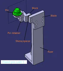
Pin Unit Design
OK-VISE®
Generic Purpose SystemOK-VISE®-Fixturing Concept
OK-VISE’s GENERIC PURPOSE workholding system adapts easily to various workpiece sizes, and the components of these systems can be reused and reconfigured easily for a variety of applications and workpieces.
Burn through protection for welding of thin material
For welding of thin material thickness 1.0mm and below the execution is to be made with burn
through protection.
Burn through protection parts / back up blocks have to be made out of Material Ampco 21 ® or
ceramic.
12 Mechanical standards
Bolts / washer / thread / dowels
Use outer hexagon head bolts in priority, inner hexagon head bolts can be used only when it’s not
possible to work with outer hexagon head bolts.
In high spatter areas, Hex Head Bolts have to be used unless change has been signed off by productresponsible AME. (If Allen-Socket Headed Cap Screws are used, heat resistant clay must be inserted
in to the bolt).
All bolts used to attach details to the frame must be M6 or greater. Anything less than this size is
unacceptable.
No US bolts will be acceptable. Utilize only Metric standard.
Hexagon head bolt
Hexagon head bolts of DIN EN ISO 4014 (DIN 931-1) see figure 6; or DIN EN ISO 4017 (DIN
933) see figure 7.-
-
-
Hot
-
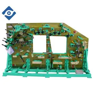
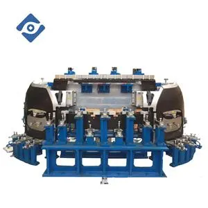
Assembly Fixture For Front Bumper
Gauge type: Assembly Fixture for plastic part Inspection type: hole position, hole size, surface profile and trim edge,flatness check,CMM inspection
-
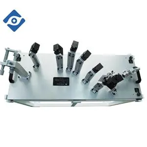
Assembly Fixture For Rear Bumper
Gauge type: Assembly Fixture for plastic part Inspection type: hole position, hole size, surface profile and trim edge,flatness check,CMM inspection
-
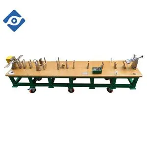
CMM Fixture For Fuel Pipe
Gauge type: CMM fixture for plastic part Inspection type: CMM inspection
-
Checking Fixture for REINF FRT VLC PNL
Gauge type:checking fixture for metal part Inspection type: hole position, hole size, surface profile and trim edge,flatness check,CMM inspectio
-
All Hex head bolts zinc patted.
Preferred dimension M6, M8, M10, M12.
All bolts must be easy reachable for assembling and disassembling
Figure 6
Figure 7
Allen-Socket Headed Cap Screws (inner hexagon head bolts)
Not to use in high risk weld spatter area!
o Socket head bolts of DIN EN ISO 4762 (DIN 912) see figure 7.
o All Hex head bolts zinc patted.
o Preferred dimension M6, M8, M10, M12.
o All bolts must be easy reachable for assembling and disassembling.
Figure 7
Set screws
According to function use following set screw types:
Inner Hexagon socket set screws with flat tip DIN EU ISO 4026 (DIN 913)
Preferred dimension M6, M8, M10.
Example for use when:
Fixation of position pinsInner Hexagon pressure screws with radius half-dog point.
The pressure screws with nipple are used when a point pressure or support point are required.
Screw quality class / Screw grade 10.9.
Pin, hardened tool steel.
Preferred dimension M6, M8, M10.
Fine adjustments are requiredBolt lock
For bolts that are used in important areas the bolt fixing has to be secure bolts with liquid bolt lock.
Temperature resistant from -55 °C to +150 °C.
Preferred use LOCTITE screw lock mid-strength.Washer / spring washer
For all screws use washer.
Washer zinc patted.
Medium washer DIN EN ISO 7090 (DIN125 type B).
To secure screws use spring lock washer DIN 128 type A.
Thread insert in weak soft and weak materials
Threaded inserts must be used for all tapped holes into aluminum or other soft / weak materials to
create a high strength fastening. Keenserts ® or Ensat ® are preferred. Tooling supplier must have
written approve for a deviation.
Preferred insert type: Keenserts ® by Alcoa
Further information: www.alcoa.com
Worldwide available
Preferred insert type: Ensat ® S302 by Kerbkonus
Further information: www.kerbkonus.de
Worldwide available
Alternative, but not preferred insert type: Helicoil ® plus by Böllhoff
Further information: www.boellhoff.de
Worldwide available
Cylindrical pins / dowel
All tooling component part locators, mounted clamps, mounted slides, and other devices must use a
minimum of two dowels per unit for location.
In prior dowel holes must have a through hole for easy removal of dowel.
Mounting dowels must have a minimum of 1.5 X diameter engagement into the adjacent
detail/member/tool plate at the maximum shimmed condition.
In first prior use through holes for dowel
o Cylindrical pins DIN EN ISO 8734 (DIN 6325)
o Tolerance class m6
o Hardened: hardness 550 – 650 HV 30 ; 60+/-2 HRC, dressed to size and lapped
o Preferred diameter Ø 6mm, Ø8mm and Ø10mmWhen no through holes possible, use cylindrical pins with inner thread
o Cylindrical pins with internal thread DIN EN ISO 8733 (DIN 7979)
o Tolerance class m6
o Hardened: hardness 550 – 650 HV 30 ; 60+/-2 HRC, dressed to size and lapped
o Preferred diameter Ø 6mm, Ø8mm and Ø10mm
o For disassembling the tread must be easy reachableOK-VISE®
Dedicated FixturingOK-VISE®-Fixturing Concept
OK-VISE’s Blank system is a system for building DEDICATED FIXTURING. Normally only one setup of one workpiece can be clamped with these fixtures. This is typical in high-volume production or when special optimization of the fixture is needed.
Position pin concept / part connection blocks
Part Ejectors have to be installed to assist the operator unload the parts. This must be used where
necessary on large to medium parts. Small parts must come out easily or ejectors must be installed.
All position pins and part connection blocks must interchangeable designed.
Position pins must stay in load direction of welding group.
If the part is pinned, and this caused unload issues in order of part geometry or heat distortion risk, the
pins must be designed for retracting / automatic removal instead of part ejectors.
Consider safety rule by automatic pin moving.
When the single part positions are made with two pins in holes with distance more than 50mm,
min. one both the position pins will be adjustable designed with shim in XY direction.
Details Position pins
In all fixtures use follow pin design, special pins could be used when it’s not possible to use the
standard pins.
Position pin material 50CrMoV13 surface hardened 52 RC hardened minimum deepness 0,5mm.
All position pins have to be locked with screws.
Welding spatter sustained metal parts or pins will be laminated with TIN (Titannitrid).
Location pins must be accessible for replacement with minimal effort in disassembly.
In General, Pin Diameter have to be based on Print Hole Nominal Size (PHN) – the hole tolerance
(PHT) on the print–0,05mm (0.02 inches)
Tooling Pin Design has to be based on the material part thickness and the bullet nose taper of the pin.
See picture below.
All two-way location pins must be fabricated to prevent rotation in the mounting block.
Any pin that has an orientation feature, two way pins, diamond shape pins, and other types, must have
a flat built on one side of the pin. Any design deviations must be approved by the AME if there is a
new concept for pin orientation.
Pin length is required on part material thickness:
Straight length of pin = Material thickness + 1.5mm
Angle of spike 60 degree, min. 4mm length.
Proportion for pin guidance to pin diameter must be design according technical rules.
Pin version with set screw clampingM Weld Fixture (Metals)
Pin version with outer thread or inner thread. All Part pins are to be tapped for M8 or M10 bolt / nut.
Part detail will have through-hole in detail for pin bolt to mount to the part/fixture detail.13 Ergonomics
Detailed information: JCI Hazard Recognition Tool for Ergonomics (HRT4Ergo)
In fixture design consider mandatory that red areas of ergonomic sheet below are not usable for part
location.
14 Fixture loading / unload strategy
Fixtures design in first strategy to easy load the single parts and easy unload the welding group.
Consider items below in design.
Fixture-design with auto-eject function / nest free for loading. Description: Welded part will lift out of
the fixture for example with a gripper system, after the fixture is open in loading area (worker side),
then the fixture is ready for single part loading.
Fixture design with stable pre-position items to help the worker with single parts easy and fast loading
process.
In priority the fixture will be designed to clamp single parts in automatic process, but all toggle clamps
applied with hand lever to allow the worker to close the toggle clamp by hand. This helps the worker
by loading of complex or strong parts.
Complicate or very small single part mandatory to clamp from worker by hand to secure a clamping
problem.
If necessary the fixture will lift out of position pins or position pins will remove.
Use pre-positioning stoppers for easy loading.
The fixture weight will balance according to the force of turning axes of welding cell.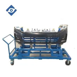
15 Poka yoke
First priority the fixture will be designed according to a Poka-Yoke system with mechanical solution.
1. mechanical protection against anti rotation
2. mechanical protection against incorrect position
3. mechanical protection against insert incorrect part
In case that mechanical Poka-Yoke is not possible, the Poka-Yoke solution must be designed with
electric sensors solution.
4. Part identification (same part in different nests or fixtures) must be provided. If it is not cycle time
relevant, welding spots are preferred.
For example; Nest 1 = spot in left corner, Nest 2 = spot in right corner. If a welding spot increase
the cycle time in that way that customer tact will not be reached, also a punch mark (integrated in
the clamping) is possible.
16 Torch position – Torch angle
Access to welding seam and welding torch angle. see figure 1
Clearance for welding torch: minimum effective welding seam length (shown in CAD model) +
5mm lead in/out + 5mm welding seam tolerance (summary + 10mm)
Weld torch access must have a 5mm clearance from any fixture point
Welding torch 22° (goose neck)
GMAW Torch Angles must have torch clearance, for all arc welds, within 45 degrees +/- 10 DegreesWork Angle to the weld root and +/- 10 degree-Travel Angle, Forward Angle 0 Degrees
Figure 1
17 Fixture calibration
All fixtures are to be measured and adjusted in zero design position, maximum deviation to design 0
position +/- 0,05mm.
Each fixture must have 3 CMM measuring balls or holes with covers as part of the fixture design.
The measuring points x, y, z coordinates have to be labelled, Label firm fixed with blind rivet on frame.
Easy access for measuring tool should be considered.
Protect this area in production against welding spatters.
If there are separate Plates for each tool within a frame, then each tooling plate must have the CMM
balls / holes for measuring the tool.
On a frame the tooling plates will be mounted to it, so more than one tooling plate can be placed in
front of a robot.
Test report include delivery report is part of the approval process.
Measuring drawing include.
All screws after first calibration are marked with colour to make visible that the screws are fixed.
Shim log in basic of first assembling / first calibration is content in documentation
There must be also a changing unit description, (part-matrix, version-matrix, unit location and how to
change the units).
18 Measure spikes user frame fixture
To define the user frame measure spikes on fixture needed.
Three tooling points on top of the fixture are required. The three points have to be mounted on the
fixture so that each robot can reach all three points. If necessary, each robot may require their own set
of points on the fixture (top and bottom side) depending on the reach of the robot and tooling access.
The spikes have to have a protect-cover.
or
The user frame must be defined before starting the robot welding programming.-
Checking Fixture for REINF RR ST BEL ANC RH&LH
Gauge type: checking fixture for metal part Inspection type: hole position, hole size, surface profile and trim edge,flatness check,CMM inspection
-
19 Part presence - sensor controlled
Part present sensors are required for each and every part loaded into each fixture.
Integrator must assume that it is also required for Weld Nuts as well, even if they are not welded in the
fixture but are expected to come as part of the assembly.
In case the pre-welded- group will proceed in the welding process, the presence of this group can be
made with one present sensor.
In case that a pre-welding group is produced in this fixture and will proceed into a next welding step,
the presence of this group can be made with one present sensor.
Check with JCI/AME for the expected parts there is a Poke-Yoke in place for each tool during the
quote phase.
In General, Part Present sensors have to be engineered to reduce downtime. Tooling
Supplier/Integrator is responsible for placing the part sensor location in the area where it will be most
likely to have no sensor failure due to spatter or heat damaging to the sensor face, side and cable.
20 Fixture Visualization
21 Quick Change Over
Welding cell / fixture connection for JCI standard welding cells, Connection table / fixture with pins to
define a repeatable fixture position. For electric and pneumatic connection of exchange units use
metal plugs and metal sockets Supplier: Harting
Type for electric and pneumatic connection:
HAN-modular, twin system electric and pneumatic in one plug system
Quick Change Over Procedure
1. Quick Change Over in process
2. Bring fixture in change position (worker side)
3. Pull Plug contact (air, electric)
4. Bring change device with forklift to fixture and connect
5. Open screw-connection from fixture to quick change ridge
6. Take off fixture
7. Bring fixture to the allocated space
8. In the meantime change the part allocation
9. Pick up new fixture with change device and bring it to the cell into the change position
10. Put fixture on locating pin and displace fixture
11. Close screw-connection from fixture to quick change ridge. Bring change device out
12. Connect Plug contact (air, electric)
13. Choose new fixture program
14. Load fixture and start welding
15. After the first part is welded supervisor has to make a visible check of the part. Is the
result n.o.k. the robot has to be re-teached and the welding starts again.
After visual o.k. check from first part supervisor has to bring part to the cut &etch
16. The production starts right away after the visual o.k. check. Produced parts cannot be
shipped to the customer until the cut & etch check is o.k.
17. If the cut & etch check is n.o.k., robot has to be re-teached, produced parts have to
be re-worked. After o.k. cut & etch, produced parts are released
Example device for tool-change
Europe system:
Drawing from mounting Blocks you will find in the appendix.
Electric and pneumatic connection, fixture to weld cell on right side of welding fixture with enough wire
length to switch the connection to the left side in case we need to switch the fixture from right to left
robot side.
Centre device axis of rotation at operator side 900mm to 1050mm above floor.
Air connection, fixture to welding cell with quick coupling socket/plugs. Male connector on welding
fixture, female connection on welding cell.
Electric connection, fixture to welding cell with quick coupling socket/plugs. Male connector on welding
fixture, female connection on welding cell.
Johnson Controls Automotive Experience
Global Supplier Standards Manual
Design & Execution Requirements for Production Weld Fixture (Metals)
Cell fixture dimensions
Basic Arc Cell / Basic Spot Cell
Compact Arc Cell
Compact Laser Cell
4-Station Laser Cell
Johnson Controls Automotive Experience
Global Supplier Standards Manual
Design & Execution Requirements for Production Weld Fixture (Metals)
December 2015
Uncontrolled if printed JCI GSSM Weld Fixture (Metals)
December 2015 Page 32 of 53
Fixture Controls
Main PLC Siemens S7 CPU S7-1516F-2PN/DP in Cell as master.
Slaves on fixtures are standardized FESTO remote I/0-Systems CPX in combination
with the valve terminals VTSA; communication interface Profinet (Ethernet).
Festo CPX + VTSA
CPX: Festo Remote I/O-System (Profinet) communicates with the main PLC Usable as: stand-alone
unit; remote controller Ethernet; remote controller fieldbus; remote I/O-unit as slave
VTSA: Festo Valve Terminal Individual configurable – depending on the number of needed I/Os
Quick connect for electrical power and interface with HARTING Overview Jig Plug connectors –X1/-
X2/-X3/-X4
Pneumatic quick-connect, Festo, type KS4 will be used as pneumatic connection between cell / fixture.
Global Supplier Standards Manual
Design & Execution Requirements for Production Weld Fixture (Metals)
North America System:
Figure 3 — JCI Head Stock Mounting Plate -– Use this design unless a deviation is approved by
JCI/AME for the program. (Note: Integrator to Machine Plates and mount them to the Fixtures).
Figure 4 — JCI’s Latest Design –- “Tool Retainer “at the Head and Tail Stock Positioner Plate (Note:
Integrator to purchase Tool Retainers from Automated Systems, Inc. and mount them to the positioner
Head/Tail Stock plates
Figure 3
Figure 4
Fixture Control
Main PLC Allen Bradley Compact Logic Guard Logic 1768-L43S/L45S Control Logic
Guard Logic 1756L63S/L65S1756-L7xS.
All fixtures must be equipped with Allen Bradley Micro-logic 1200/1400/1500 processor with 14k user
memory. The Micro-logic must be capable of communicating to a SLC 5/05 via an ENI module and
Ethernet hub. The Micro-logic processor must also be capable of communicating with the Allen
Bradley Control-logic platform.
Quick connect for electrical power and interface
Amphenol Male Amphenol Connector, 18 pin, 1/4 turn MS-3116-F14-18P
Amphenol Female Amphenol Connector, 18 pin, 1/4 turn MS-3116-F14-18S
Amphenol Flange Mount Male Amphenol, 18 pin, 1/4 turn MS-3112-E14-18P
Welding cell / fixture connection for re-used welding cells
For detailed welding cell information and welding fixture connection of reused equipment ask the
responsible project AME.
Fast change system for fixture exchange elements
For fixture exchange elements use fast change system with swash plates, hardened screw bolts and
hardened position pins / hardened bush. Example below, Figure 5
Figure 5Part Supplier: Norelem (www.norelem.com)
Type: Swash plate Norelem order nr: 07520-08 according DIN 6371
Bolt Norelem order nr: 07530-06 Screws
Nut Norelem order nr: 07240-08
Bolt DIN 939- M8x55
Position of exchange units will be repeatable in using of hardened bushing according DIN172 / ISO
4247 and hardened pins, one round pin and one sword pin, see picture
Hardened Pin: diameter Ø 10mm, clearance m6
Hardened bushing according DIN172 Form B / ISO 4247: inner diameter Ø10mm, clearance F7
Position pins / bushing has to be protected against weld splatters
For each exchange group use mechanical Poka Yoke, mandatory only one position over all
same fixtures can be possible to mount. All exchange groups variances have to be controlled
via welding cell PLC. Solution for detection has to be made with separate sensor.
All exchange groups have to be designed with 3D shim system to make sure that all parts
could have different adjustments.
22 Electric cable, sensors, etc
Observe the regional rules and different brands for NA, CN and EU
For reused equipment ask responsible AME for detailed information
Sensor types / proximity switches for part present detection
Regarding to distance of welding area select the sensor type see table below
Distance to welding area more the 200mm
Distance to welding area 20mm – 200mm
Distance to welding area < 20mm
Remark: Steelface W51- ceramic coated sensor brand Balluff
Inductive sensor M8x1 preferred size
o With 2mm rated switching distance
o Yellow LED for signal
o M8x1 plug connection
o 3 pin plug
o IP 67 protection
o Example Supplier: IFM / Sensor type:IE5338
o Example Supplier: Balluff / Sensor type: BES00CK
o Close to welding area mandatory use ceramic coated
Different brands see released component listInductive sensor square 8x8
o With 2mm rated switching distance
o Red LED for signal
o M8x1 plug connection
o 3 pin plug
o IP 65 protection
o Example Supplier: IFM / Sensor type:IL5004
Different brands see released component listNot preferred but for special task usable, photoelectric or laser sensors, special protection needed.
AME release required.
For NA consider SESS and SEGS.
For EU consider Technical Order Conditions.
Sensors will be protected against welding spatters, use weld spatter protected shuck such as Balluff
brass sleeve to protect the thread to sensors.
Mandatory all sensors are to be labeled.
Sensor positions will be aligned considering accessibility and sensor light visibility.
Sensors and initiator from cell and fixtures will be self-controlled, get back so PLC controlled zero
signal after removing the welding parts.
In fault situations the number of faulty sensor will be indicated at the welding cell HMI.
In case of limited space to mount a part sensor on extra device, the sensor can be located directly in
the block.
Don’t use thread for fixing when a Sensor is direct mounted in a fixture part or fixture block.
Example for good solution sensor-switch fixation / mounting:
Clamp sensors in brass tube (open slit) with set screw, very easy to set the sensor in right position.
Example for indirect part control of small parts / close to weld seam
Close to welding seam use Fixing stop cross applicable.
Fixed stop combined with corresponding mounting cuff.
Switching point between the sensor switch and trigger pin can be set wherever needed.
Balluff BES 08-FA-49 order code BAM009L
Size M8x1
Stainless steel
Spring force 3N
Spring deflection 2mm
Use Balluff BES 08-FA-BS-8,0-W order code BAM009T.
With this part the switching point between the proximity switch and trigger pin can be set wherever
needed.mounting view with BAM009T view without BAM009T
Part sensors located in welding spatter free areas or areas where the risk of spatters is low
Sensor cabling
Cabling has to be done properly not to disturb shim and mechanical adjustments. (cable installation
should be in / under base frame in cable trays etc.).
Connectors sensor side, M8 female, 3-pin, no LED and right angle preferred
Sensor cables on moving parts need a cable relief.
Mandatory all sensor cables are welding spatter protected with metal / silicon fibre protected hose.
Sensor cables will be protected against mechanical damage.
Mandatory all sensors supply with 300mm cables. M8x1 connection / plugs for easy maintenance,
direct installation / connection in electric cabinet not allowed. Cable example: supplier Balluff / type:
BCC0CAN
Different brands see released component list
Labelling of sensor, sensor switches, clampers, piston and valves
All solenoid valves and air cylinders are to be clearly marked with
Brass or Aluminum tags at or near the solenoid or cylinder area for
identification.
Brass or Aluminum tags shall be mechanical labeled near cylinder or
slide location with the actual PLC address.
Brass or Aluminum tags also have the Valve Number used for the
cylinder or slide. This will allow us to understand which valve actuates
the cylinder or slide. (Example V#1 or V#2).
The Valve Stack on the Fixture also to be listed in order starting with
V#1, V#2, and so on to complete the valve fixture traceability.
Valve Stack Pneumatic and Electrical Drawings include the V#1 designations as part of the
Descriptions in the drawings or other documents.
Examples:Pin Unit Design
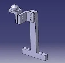
23 Special feature Laser welding fixture
Basic construction rules
Fixtures have to provide zero gap condition (zero gap first, structure tolerance second.
Clamping devices must be equipped with quickly changeable downholder pins.
Pneumatic clamping devices have to be equipped with end position sensor.
Fixture locators have to be designed according Poka-Yoke-principles.
Parts must be ergonomically provided for take-out.
Parts must be capable fixed by a manual closing process. Pressure might be automatically applied to
clamping system in a second step.
The number of manual closing processes has to be reduced to a minimum (e.g..: only one closing
process for upper lid of clamp shell device.
The manual clamping force must stay below 150N.
Functional areas must be prevented from weld spatter and unintended laser radiation.
Gas nozzles or air knives must be adjustable.
Gas application system must be secured against unintended displacement
Basic product/welding fixture matrix
Type of fixture clamp shell toggle clamp upside down concept disk standard
FSB x x o o
RSB x o o o
track (lap joint) x x x o
recliner (lap joint) x x o o
track (butt joint/T-joint) o o x o
recliner (butt joint) o o o x
x BBP
o not feasable or critical
Laser Fixture application matrix
Clamp shell fixture FSB
Clamp shell fixture RSB
Johnson Controls Automotive Experience
Global Supplier Standards Manual
Design & Execution Requirements for Production Weld Fixture (Metals)
December 2015
Uncontrolled if printed JCI GSSM Weld Fixture (Metals)
December 2015 Page 43 of 53
Beam access clamp shell fixtures (opening in upper lid)
1) Weldseam with lateral welding angle
10mm seam length: X = 1+5+2+(10+5)+2+5+1 = 31mm
15mm seam length: X = 1+5+2+(15+5)+2+5+1 = 36mm
20mm seam length: X = 1+5+2+(20+5)+2+5+1 = 41mm
The width y depends on the lateral angle, the beam cone, the seam pattern and the distance
between upper lid and working point on the part
2) Weldseam with longitudinal welding angleThe length x depends on the longitudinal angle, the beam cone and the distance between
the upper lid and the working point on the part
Toggle clamp fixture FSB
Upside down concept
Johnson Controls Automotive Experience
Global Supplier Standards Manual
Design & Execution Requirements for Production Weld Fixture (Metals)
Basic principle ‘downholder system’ for recliner welding
24 Connection fixture reused welding cell
Observe the regional rules for NA, CN and EU
For reused equipment ask responsible AME for detailed information
25 Examples GMAW fixture solutions
Single seat backrest upper crossmember / headrest form tubes
Good working solution
Position parts on rail, pneumatic movement shim adjustable in XYZ
Backrest headrest tubes welded on tubes
Welding fixture 2 way cushion
Fixture overview
Welding fixture size: 2000mm 2 welding nestFixed Pin Unit and Retractable Pin Unit Design
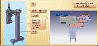
Pin Unit
Pin Unit Design
BIW fixtures - Pin unit design (fixed pin & retractable pin units)
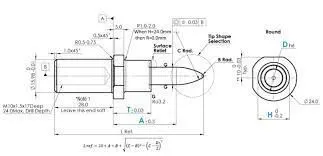 BIW fixtures - Pin unit design (fixed ...
Metal SMRT King Pin Unit,
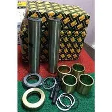 Fixed Pin Unit and Retractable Pin Unit Design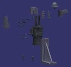
Fixed Pin Unit and Retractable Pin Unit Design

today scenario customer need the best quality for fit and finish of his car, they don’t compromise on these parameters. Body coordinate are to be maintain within tolerances for good quality, productivity, safety , efficiency etc
To establish the dimensional tolerances in Press and weld parts of four wheel automobile bodies so that balance in the quality can be achieved which results in improved efficiency Shimming plays very important role for that as detail below.
Body-In-White (BIW) is a complicated steel-structure made up of 200~500 press panels with simple & complex shape based on Car design , shape safety feature and many more requirements.
Based on cycle time , Typically many welding fixture are use to hold the car panels in desired position to make sub assy. More than 50 sub assy need to made in smaller fixtures and than joint in main fixture to make bigger sub assy and finally Main body shell and doors made separately to fasten with Main body shell to make White body (BIW)
There is acceptable tolerance in each process of panel making , sub assy making and than final body making
There are more than 1000 points need to be check and maintain to make BIW within the tolerance of +- 1.0 mm . It is very tedious work and during prove out time, shimming play a pivotal role more detail below
General tolerance used in BIW making process are below
Stamping ( Press panel) & Welding Jig tolerances
Datum hole dia +- 0.1 mm
1, Locating Hole +0.2 -0 mm,
2, Locating hole pitch +- 0.2 mm
3, Common hole dia + 0.5 - 0.0 mm
4, Common hole pitch & position +-0.5 mm
5, Spotting surface +- 0.7 mm
6 General profile +- 1 mm
7, Locating pin Position +- 0,2 mm
8, Pin to pin Pitch position too +_ 0.2 mm
9, Receiving Panel position on Mylar +- 0.3 mm in x,y, z direction
As it is very very difficult to produce all the panels or sub assy with zero tolerance. Panels with all the above tolerance are acceptable or based on customer standard
However if all these tolerance go in one direction /Tolerance stack ups. Even though you may be able to hold tight tolerance within one part, in a weld fixture you might have a base plate with a block mounted to that, with a pin mounted to that. Each new part and each new feature on a part has it’s own small tolerance. It could be as small as +/-0.01 mm but you add that up a few times in the same direction and pretty soon your pin will be in more than 1.0 mm out from base point in the fixture.
Each fixture will have 2 to 25 numbers clamping unit , Each clamping units have more than 25 machine or fabricated parts & fasteners , some times in main body fixture it can be 50 clamping unit too
You can just imagine the shape of BIW how much it will be out if all the tolerance are stack-up in one direction and difficulty in fitting assy parts and noise level wear out .
Typically one clamping unit picture is below
The accuracy of all the Mylar , pins and machine parts are very very important and heart of body accuracy in BIW
Depending on our customer requirement and the amount of precision needed, we have designed metal adjustment shims into our weld fixtures.
This is how it works:
1) It help in adjustment shims packs, Mylar, locating pin etc;
2) It help to weld the product parts together in the fixture with desired accuracy to test it by shifting the shims add or remove, Check the welded product to see if it meets specifications & requirement during initial trials.
3) If it is off a bit, remove or add shims as needed to move the product inside the fixture to correct the problem.
5) Repeat 2-4 until the product is perfect. Then the fixture is ready to put into full production.
6) It help in adjusting the body accuracy after certain use when jigs wear out and affect of dies wear out
7) It helps in achieving the desired fitment when some plastic parts or other parts have tolerances out and not possible to retrieve
Few customer have their different shim pack standard max 3 mm (0.5+0.5+1.0+1.0), 5 mm (0.5+0.5+1.0+1.0+2), 7 mm ( 0.5+0.5+1.0+2.0+3.) or other too . Jig maker has to adhere with that before dispatching the fixture . All BIW maker use these shims for their final adjustment after period of time due to wear in Jigs , Wear in dies impacting the panel tolerances.
So Now →What is Shim & its standard for BIW fixture
A shim is a thin plate to adjust receiving panels. Shims are typically used in order to support, adjust for better fit, or provide a level surface. Shims may also be used as spacers to fill gaps between parts subject to wear. This is very important and indispensable for implementing quality improvement
-