Week 4- Meshing of Backdoor Challenge
PROJECT REPORT
AIM:
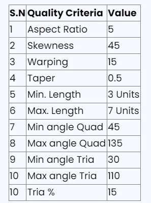
Check and correct geometrical errors on the backdoor geometry of a car and take mid surface, assign the thickness then mesh it based on element Quality criteria given below,
OBJECTIVES:
- To check and correct geometrical errors on the backdoor geometry of a car.
- Generating Mid surface and geometry clean-up on the given component
- Generating mesh on the given component with low tria concentration and proper mesh flow and assigning the thickness.
BODY OF THE CONTENT:
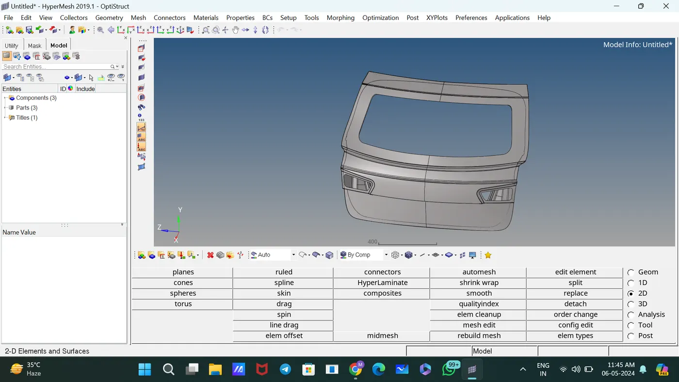
The given model is the Hood model with a thickness of 0.7.
This is the CAD MODEL,
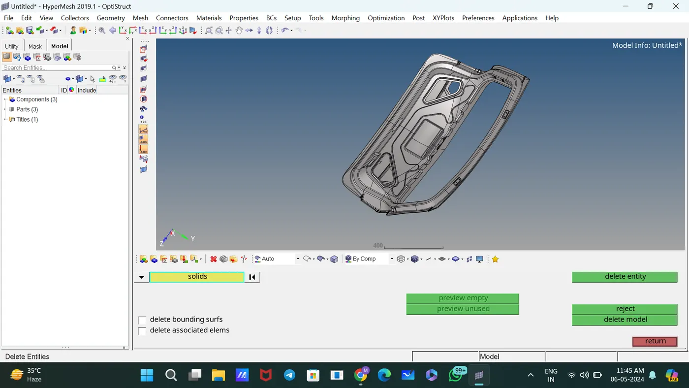
Deleted unwanted lines and solids. [Delete—select the solids and lines]
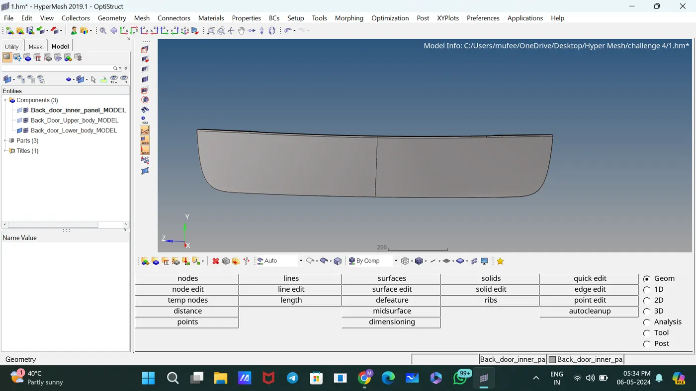
The component is divided into 3 parts,
1. Back door inner panel
2. Back door upper body
3. Back door lower body
Isolated each part and took mid surface and mesh separately.
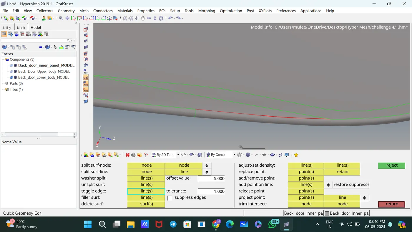
Used the Toggle subpanel to toggle edges for proper connection between surfaces.
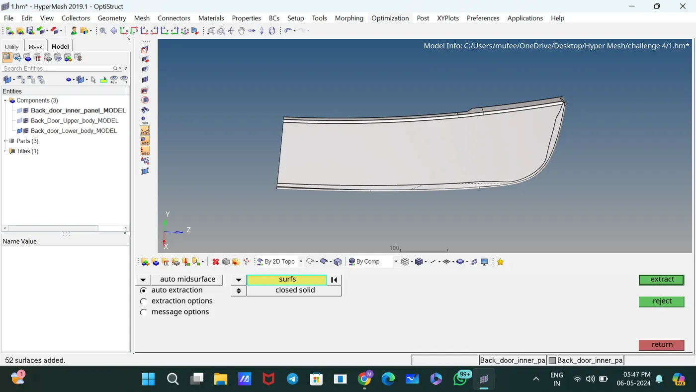
Generated the mid surface of the component using the command midsurface.
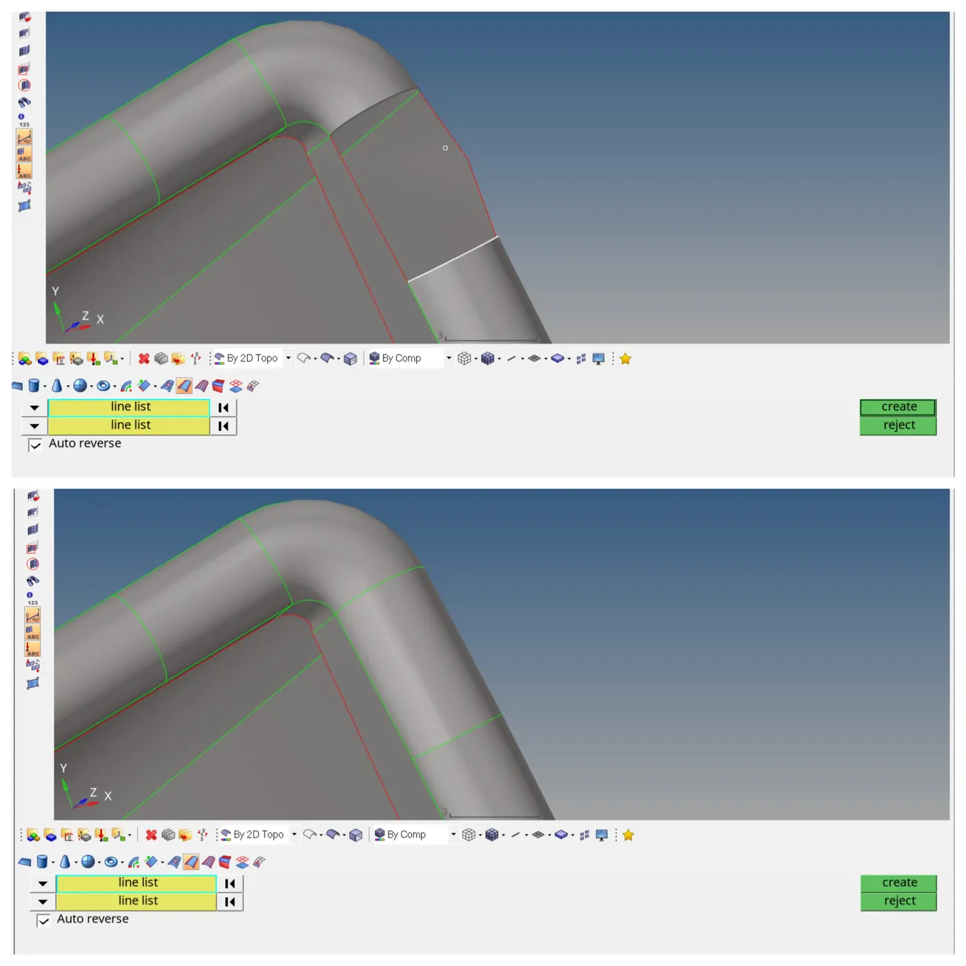
Used the Ruled subpanel to create surfaces by interpolating linearly between lines.
Assigned the quality criteria of elements in check Elements 2D.
Meshed the components with element size 5 by selecting surfaces.
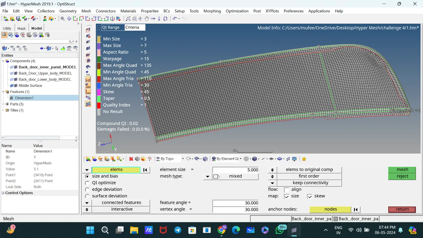
For proper mesh flow and changing tia to quads, mesh the elements and adjust the number of nodes.
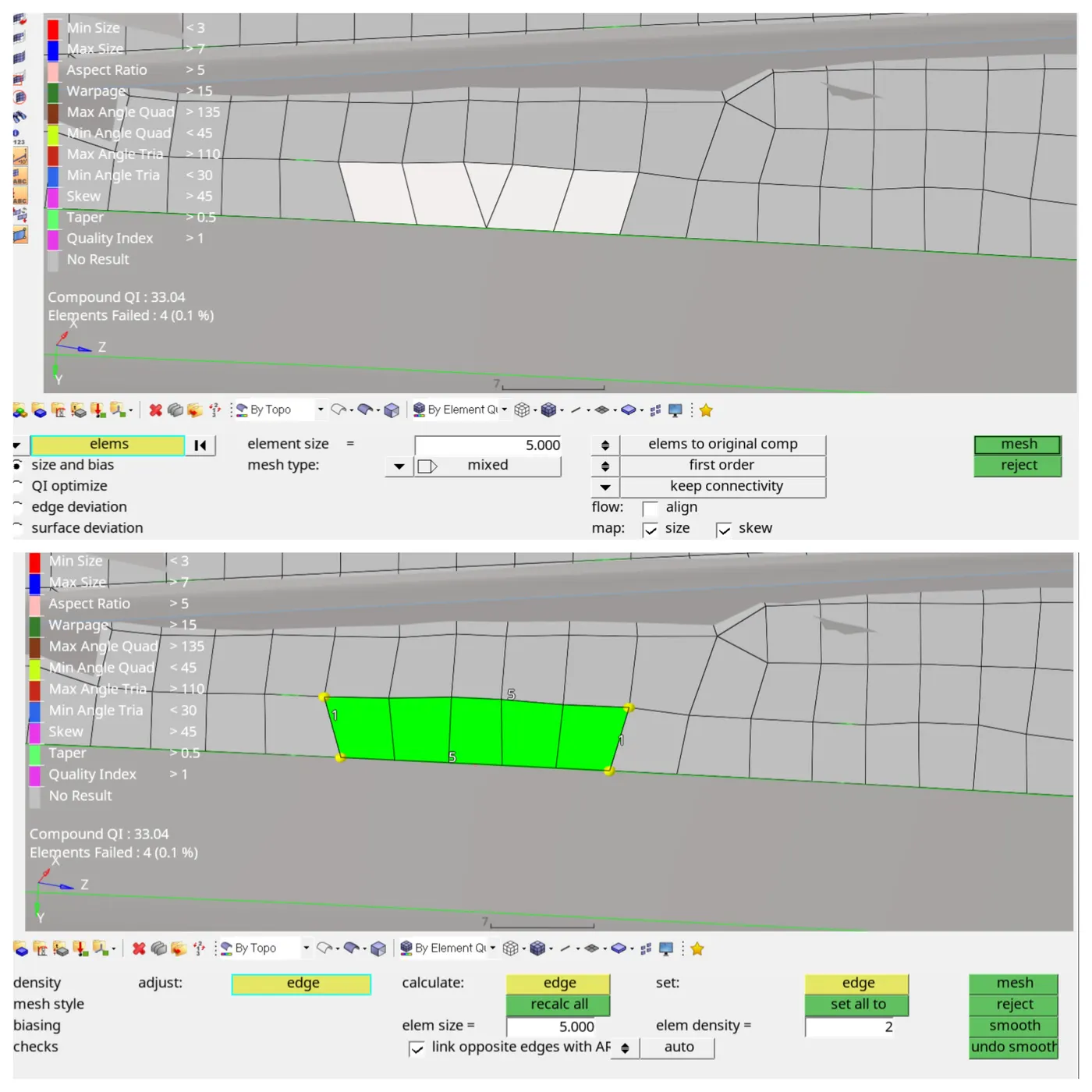
For removing rotational quads, use the slip quads and drag elements.
The symmetric meshed component is ready.
Used the Reflect command to reflect the symmetric elements [tool—Reflect]
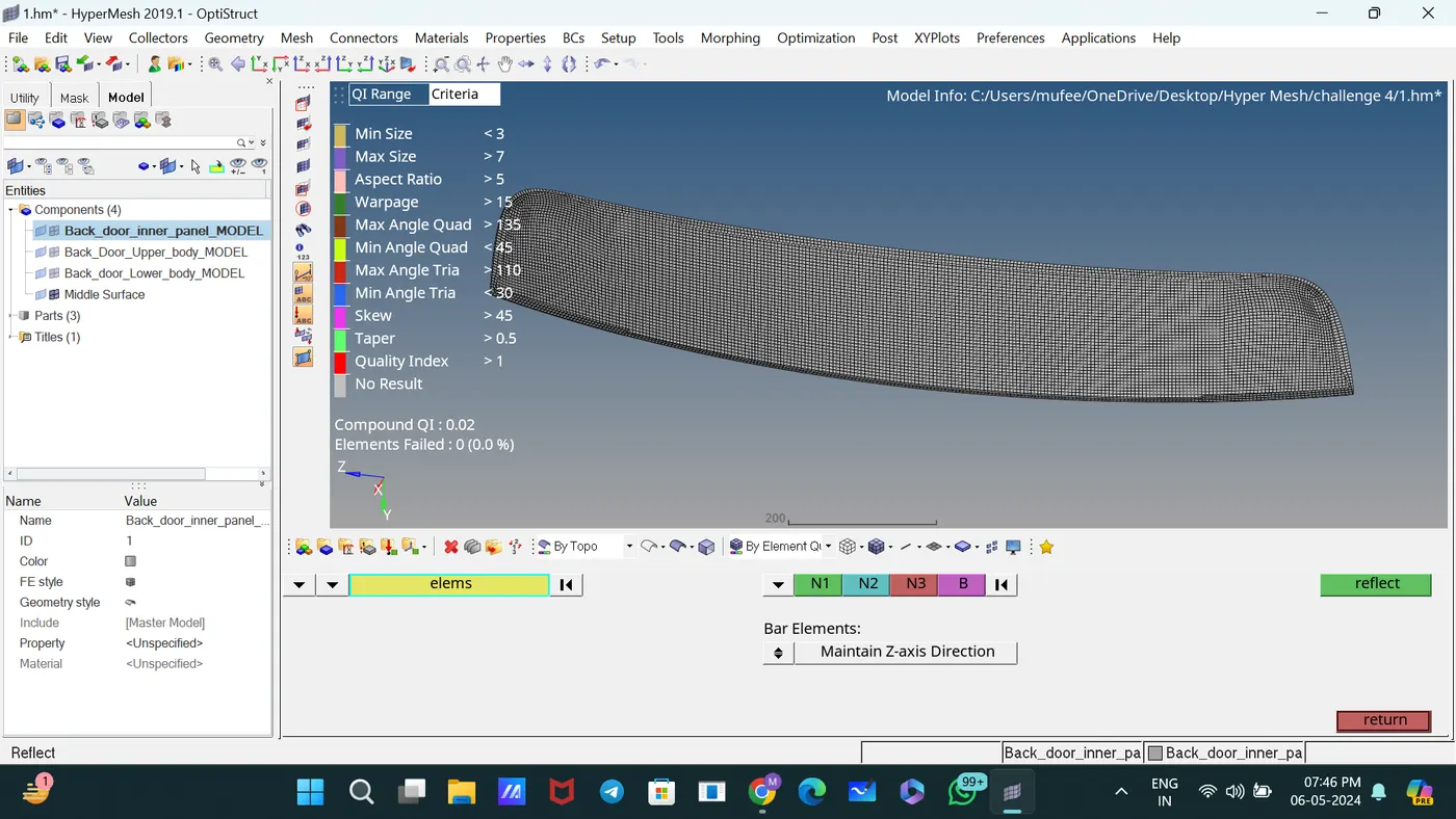
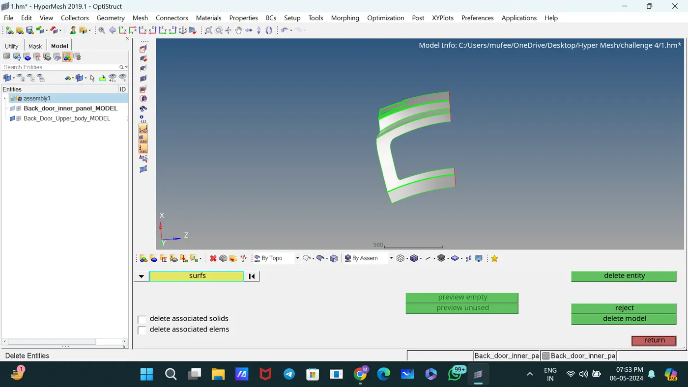
Deleted symmetric parts.
Consider next part,
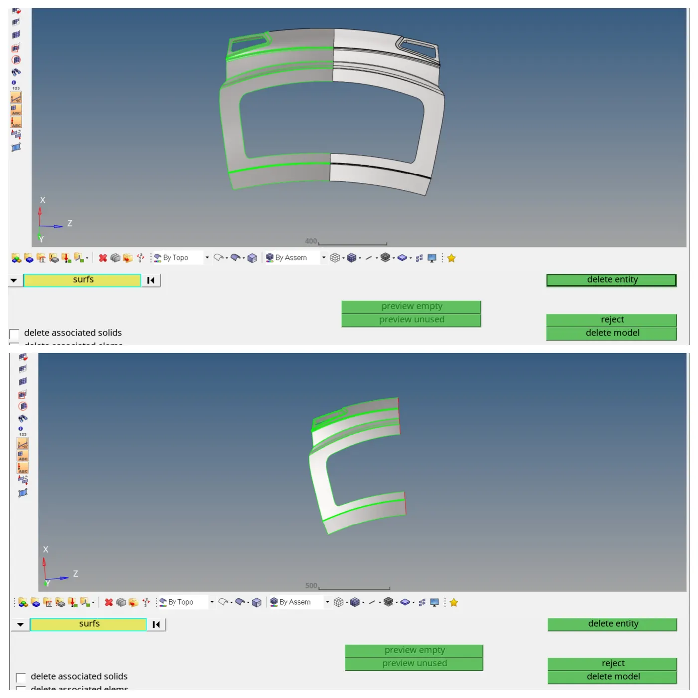
Used the Toggle subpanel to toggle edges for proper connection between surfaces.
Used the Quality Index panel to calculate a single value to represent the quality of the displayed shell (2D) model and used the commands drag tria elements, place element, and split element to proper mesh flow.
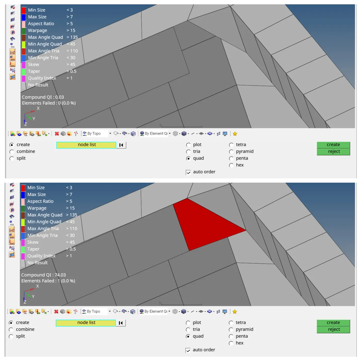
In this case, create new elements by selecting boundary nodes [element edit—create].
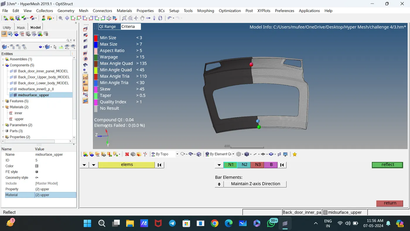
Used the Reflect command to reflect the symmetric elements [tool—Reflect]
For proper mesh flow and changing tia to quads, mesh the elements and adjust the number of nodes.
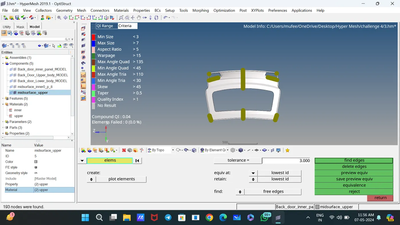
Performed the coincident node check on the selected elements and showed a temporary node at the location of any nodes identified for removal.
Performed the equivalence function by the specified criteria. It is generally advisable to preview the equivalence before performing it.
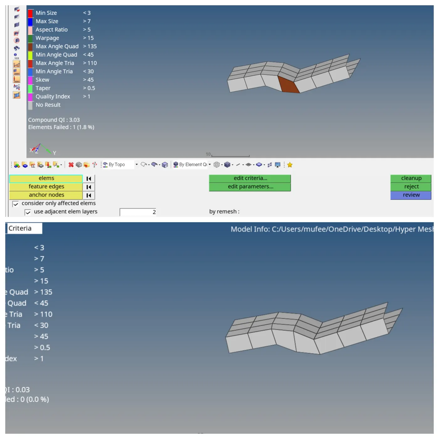
Used Auto element clean up to clean the element for accruing quality criteria.
Completed this part.
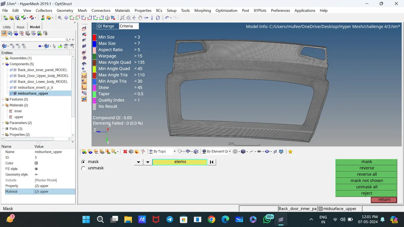
Created New material and property and assigned thickness and density.
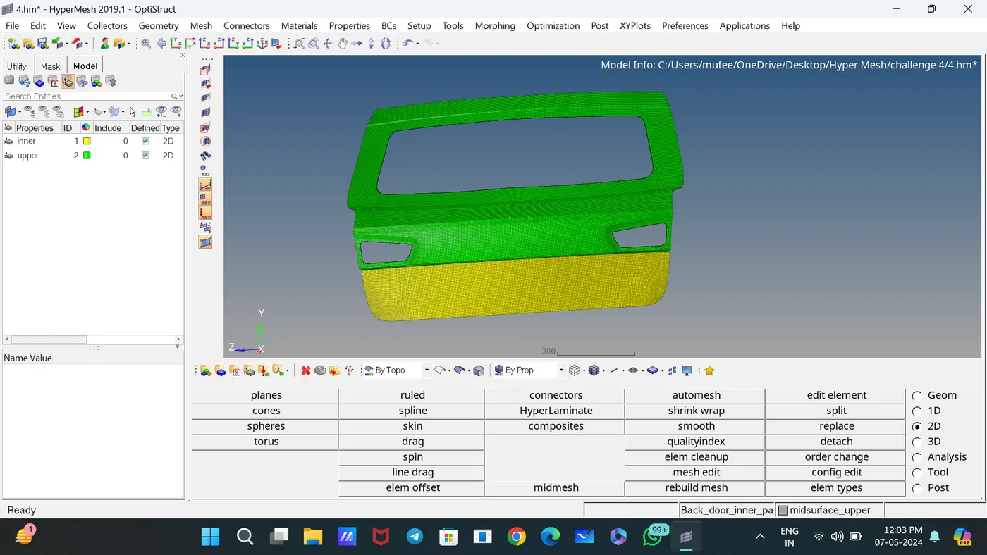
Completed the meshing of another part by following the above steps with proper mesh flow and low tria concentration.
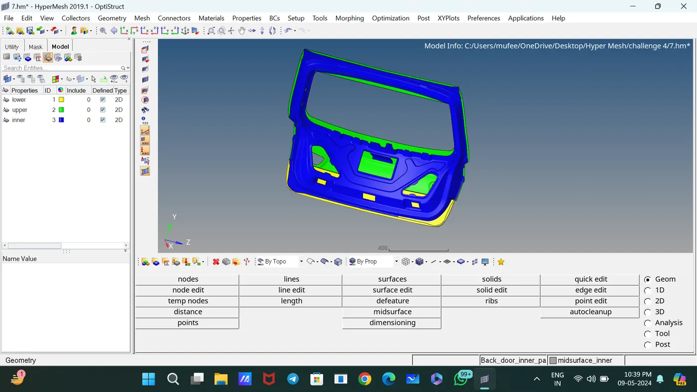
CONCLUSION:
For the given Hood model, the mid surface after checking the geometrical errors, meshed with the mid surface low tria concentration, and proper mesh flow with the given element Quality criteria.