Week 4- Meshing of Backdoor Challenge
AIM: The main aim of this challenge is to mesh the given back door as per below element quality criteria.
S.no | Element Quality Criteria | Value |
1 | Target/Average length | 5 |
2 | Minimum Length | 3 |
3 | Maximum Length | 7 |
4 | Aspect | 5 |
5 | Warpage | 15 |
6 | Skewness | 45 |
7 | Taper | 0.5 |
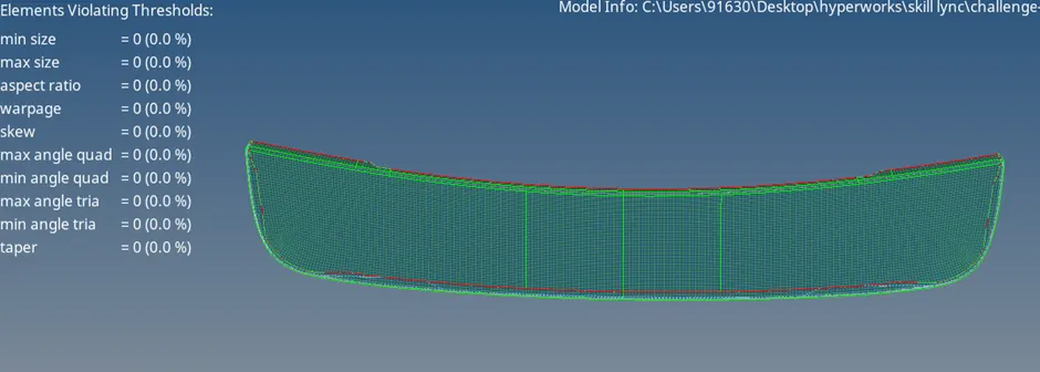
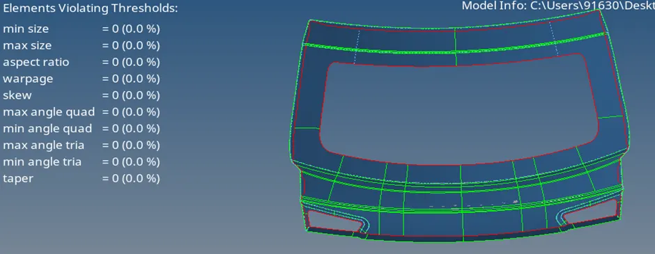
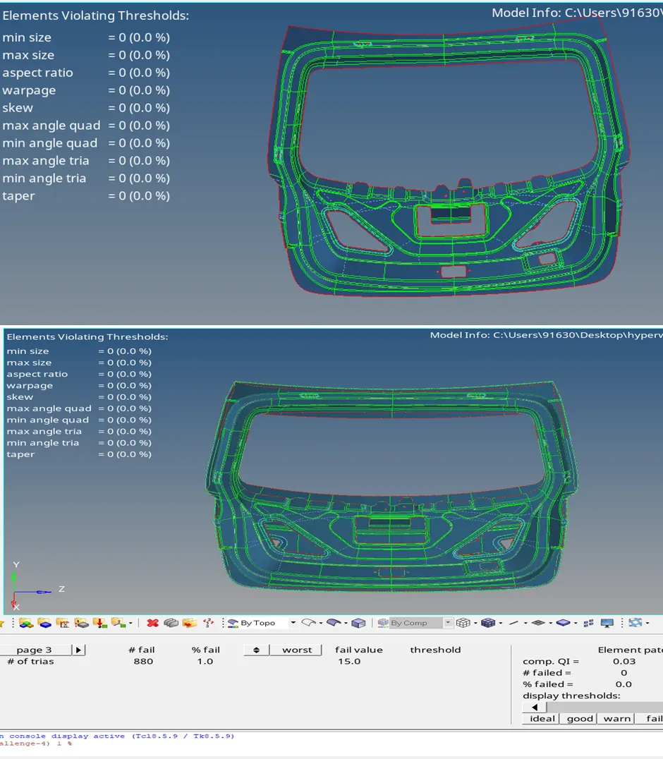
8 | Minimum Quad Angle | 45 |
9 | Maximum Quad Angle | 135 |
10 | Minimum Tria Angle | 30 |
11 | Maximum Tria Angle | 110 |
12 | Tria Percentage | 15 |
OBJECTIVE: The objectives of this challenge are as follows:
1. To perform geometry clean up and generating mid surface for the given component.
2. To mesh the given component with less tria concentration and good mesh flow.
3. Finally all the elements should pass for given element quality criteria.
PROCEDURE:
1. The CAD file in Hypermesh can be opened by selecting import model option.
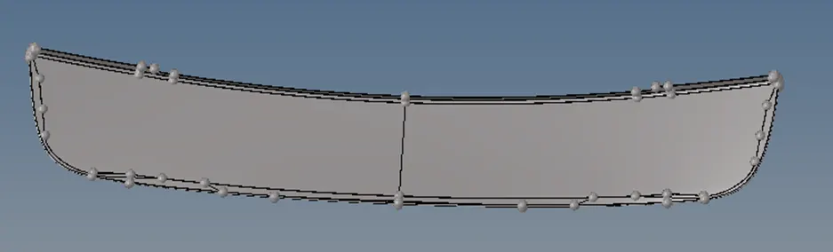
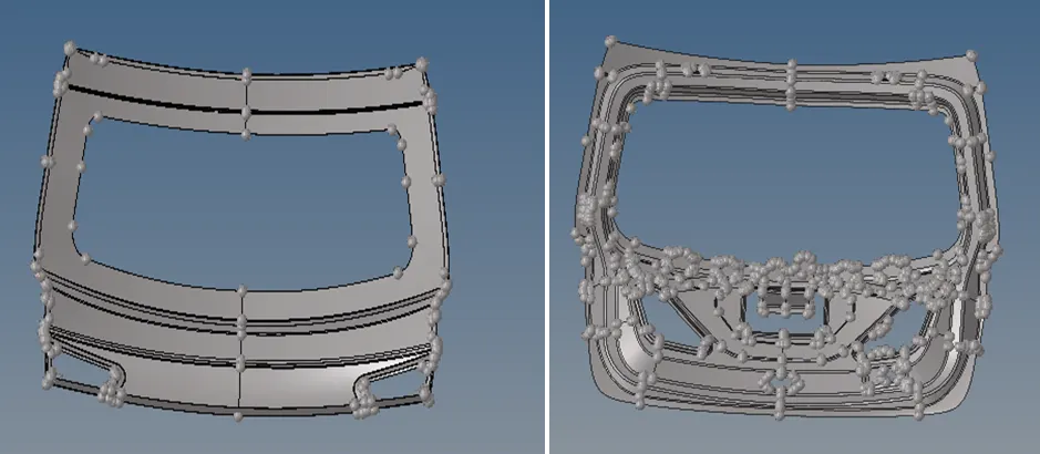
2. Totally there are 3 components in the given challenge as shown in the below and each of them must be meshed separately.
3. After opening the file, manual cleanup was performed to remove free edges and non- manifold edges.
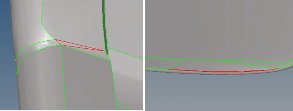
4. Several commands like split surface, toggle edges& delete surfaces were used from quick edit sub panel (GEOMETRYàQUICK EDIT).
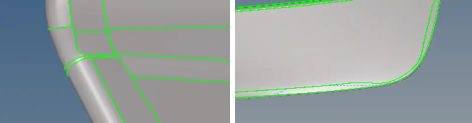
5. After removing all the free edges and non-manifold edges by manual cleaning, mid- surface was extracted using skin offset method. (GEOMETRY à MIDSURFACEà EXTRACT OPTIONSàSKIN OFFSETàAUTO EXTRACT).
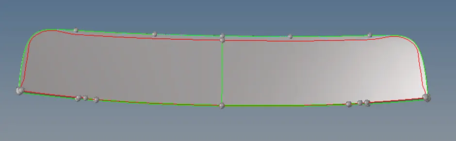
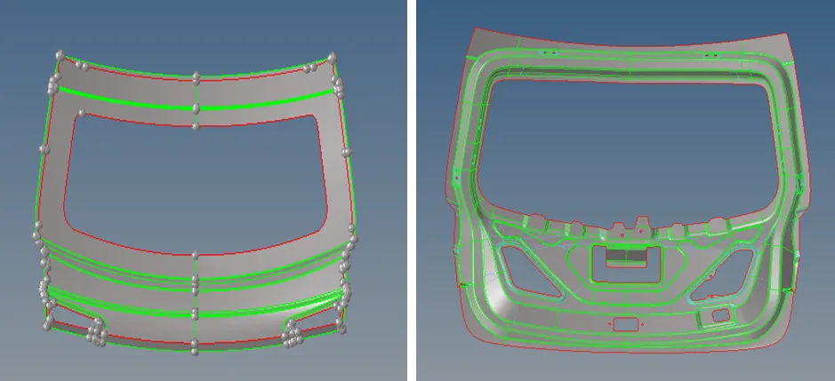
6. Since all the components in the given challenge are symmetrical components, half of the component was deleted as shown in below image followed by manual cleanup.
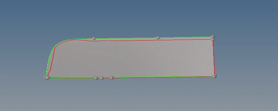
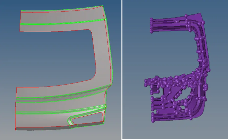
7. After deleting half component, meshing was performed using auto mesh command by importing the quality criteria (2DàAUTOMESH).
8. Elements failing at the critical features were then corrected using commands like split quad element, swap edges, element optimize, node optimize, smooth etc. from quality index sub panel (2DàQUALITY INDEX).
9. The other half of the surface and elements were then reflected using reflect command (TOOLSàREFLECT).
10. The final components after meshing is shown in the below image.
CHECKING: After finishing the following checks must be performed:
1. Checking for free edges in the component to ensure nodal connectivity. If any free edges are present in the middle of the component, those free edges can be removed by equivalence option or pasting the nodes manually (TOOLSà EDGES).
2. Checking normals (TOOLSà NORMALS) of the elements to ensure a consistent normal is maintained for the given component.
3. To find whether a proper contact has been established between elements and surfaces, we must do surface comparison (GEOMETRYàCHECKàSURFACEà COMPARISION).
4. Check for penetrations and dependency.
5. After all the checks, finally a property has been created with 0.75mm thickness and assigned to the component. To visualize this, we must change the 2D traditional elemental representation to 2D detailed elemental representation.
CONCLUSIONS:
1. Learnt about geometry clean up and extracting the mid surface using skin offset method.
2. Learnt about how to mesh a component for a given quality element criteria.
RESULTS:
Geometry cleanup, mid surface extraction and meshing of the given component was done successfully. Tria’s concentration was limited to 1%.