Week - 4 - Crash Box Simulation
AIM:
To simulate the crash test for a crash box having a different thickness of 1.2 and 1.5 mm into the rigid wall at 50 kmph and to obtain the required output data given below.
PROCEDURE:
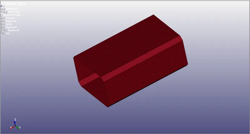
1. Initially, open the new_crash_box.k file in the LS -prepost and the unit system followed here is gm-mm-ms.
2. Then we create a shell section for the crash box and the shell section can be created using model >keyword manager>section>select shell section.
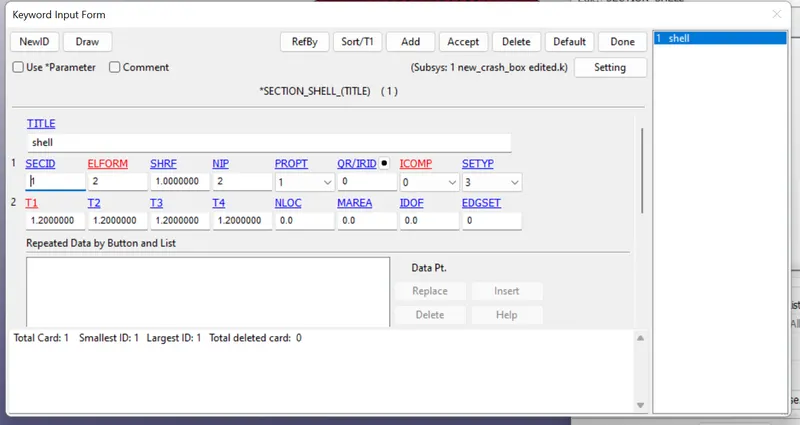
Now, thickness 1.2 mm and Element formulation =2, and SECID is provided for the shell section.
3. Material Card:
- For crash box, we will assign the material as steel which is a non-linear characteristic material.
- Go to Keyword Manager
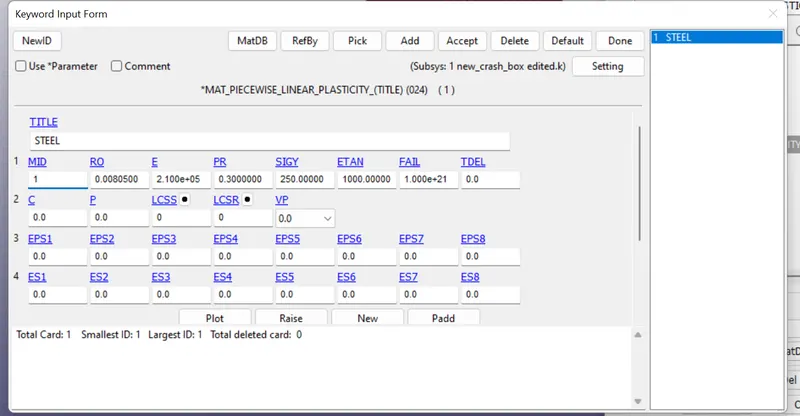
- Select MAT >> 024-PIECEWISE_LINEAR_PLASTICITY material card. Give it a material ID and title.
- As we are using gm-mm-ms unit system, we will provide the characteristic values of steel as follows:
- Density of Steel (RO) – 8.05 x 10⁻³ gm/mm3
- Young’s Modulus (E) – 210 x 103 MPa
- Poisson’s Ratio (PR) – 0.3
- Yield Stress (SIGY) – 250 MPa
- Tangent Modulus (ETAN) – 1000 MPa
4. Modelling rigid wall:
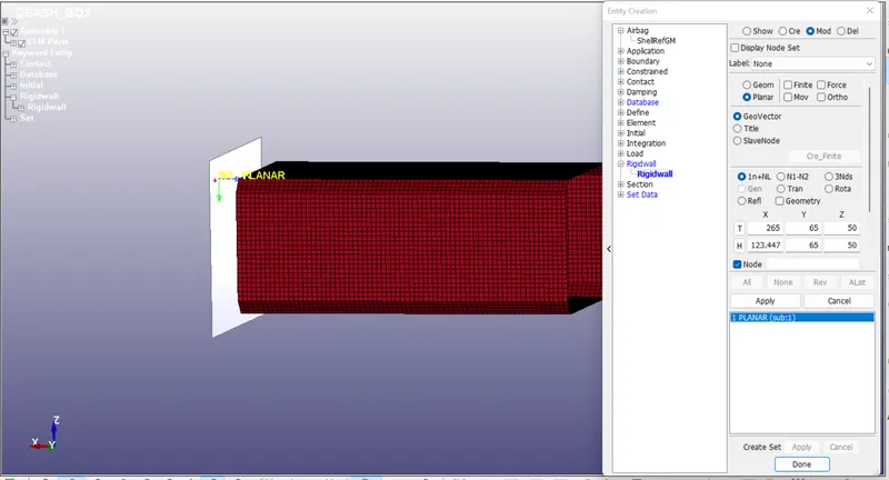
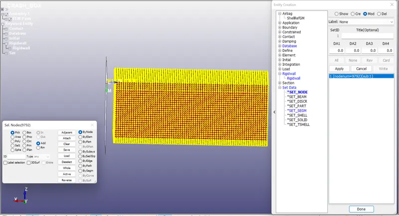
- Create a Rigidwall a few millimeters away from the end of the Crash Box. To create a Rigidwall, go to Model and Part > Keyword Mananger > Create Entity > Rigidwall.
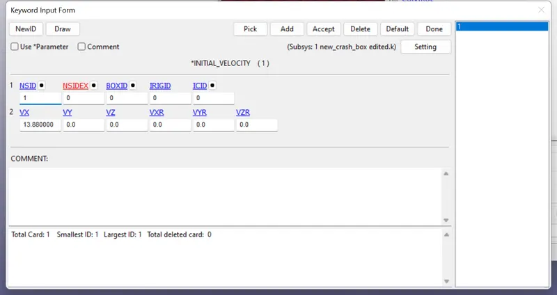
5. Similarly, using Create Entity option, create a Node set using nodes of the Crash Box and apply initial velocity of 15 kmph using INITIAL_VELOCITY card.
Velocity card:
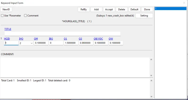
6. Hourglass:
- Hourglass can be defined using HGID. This keyword is used to reduce or control hourglass energy during the simulation.
- Go to Keyword Manager and select the values as shown below.
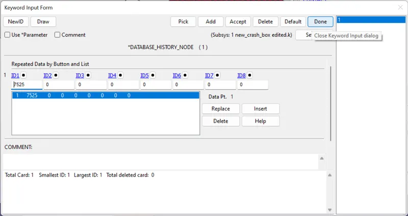
7. We have to find out acceleration of a node at the middle of the crash tube. For that, we can request the accleration of a node approximately at the centre using NODOUT option from ASCII options. First, we input the node id for acceleration calculation using DATABASE_HISTORY_NODE option.
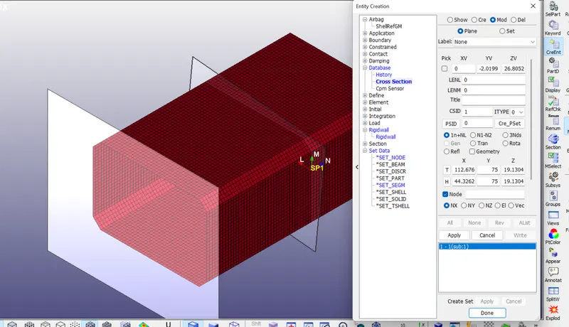
8. create the cross section by create entity.
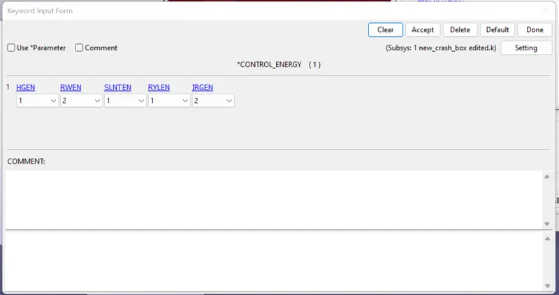
9. Control
- Energy control keyword>>CONTROL_ENERGY
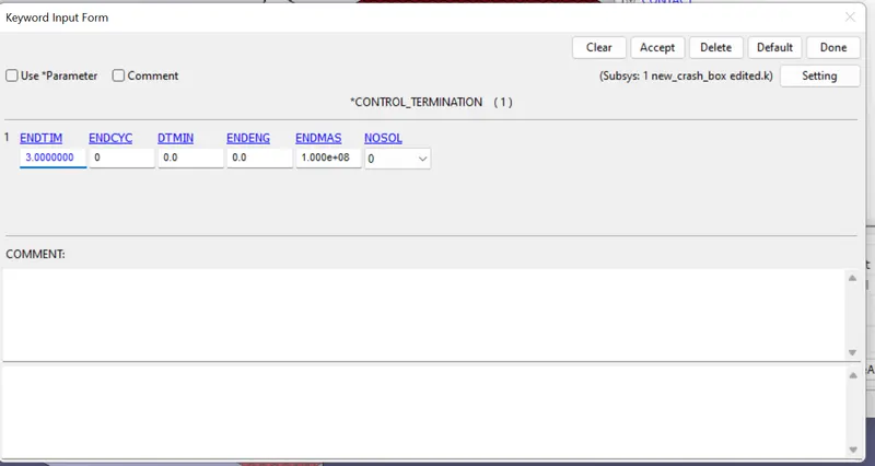
- The termination is assigned by the *CONTROL_TERMINATION card and here the end time can be calculated by taking the ratio between distance and the velocity.
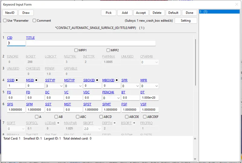
10.Using CONTACT keyword, define CONTACT_AUTOMATIC_SINGLE_SURFACE contact for the crash box as it may come in self contact after crushing.
11. OUTPUT:
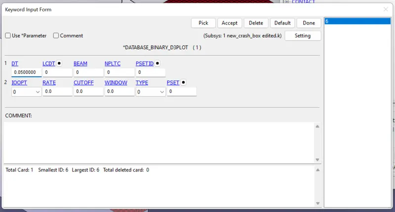
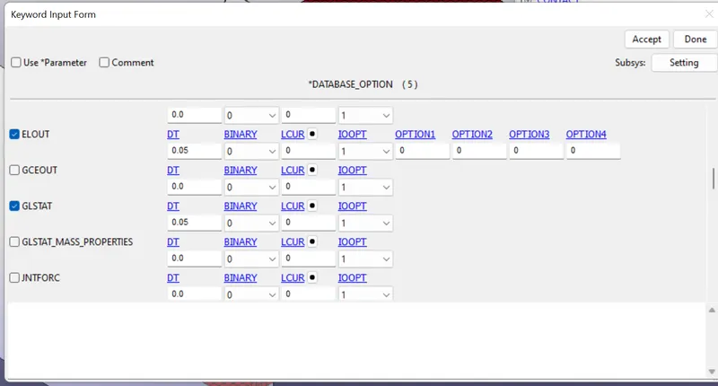
The output files using DATABASE_BINARY_D3PLOT and the ASCII_options Keyword. Time interval of 0.05 ms between the output generation is defined. Using ASCII_option, request ofr GLSTAT, NODOUT, RCFORC etc.
12. Save the key file and Run the file for the simulation.
SIMULATION:
ANIMATION OF THE FINAL SIMULATION
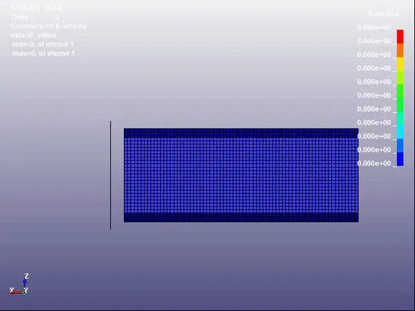
X- STRESS ANIMATION FOR CRASH BOX 1.2 MM
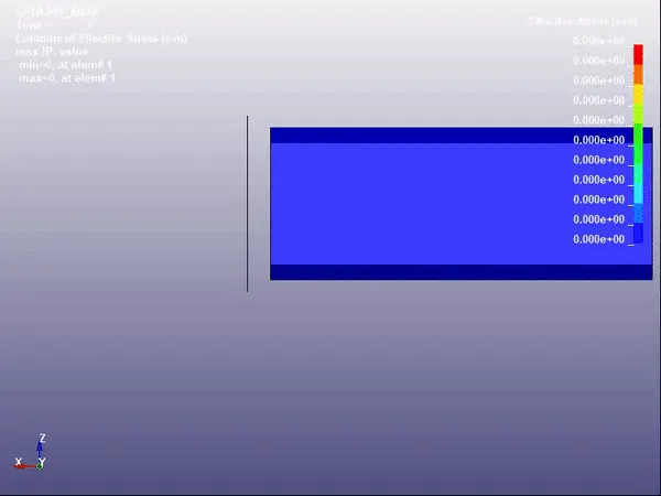
EFFECTIVE STRESS ANIMATION FOR CRASH BOX 1.2 MM
X- STRESS ANIMATION FOR CRASH BOX 1.5 MM
EFFECTIVE STRESS ANIMATION FOR CRASH BOX 1.5 MM
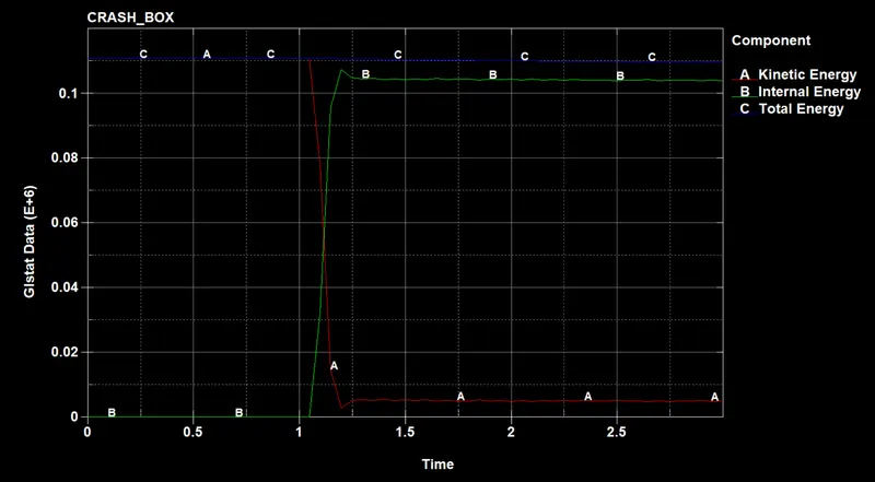
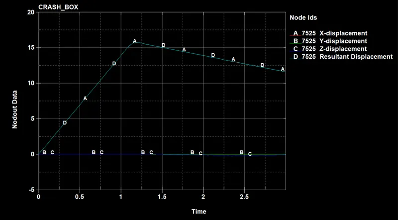
Plots for 1.2mm thickness:
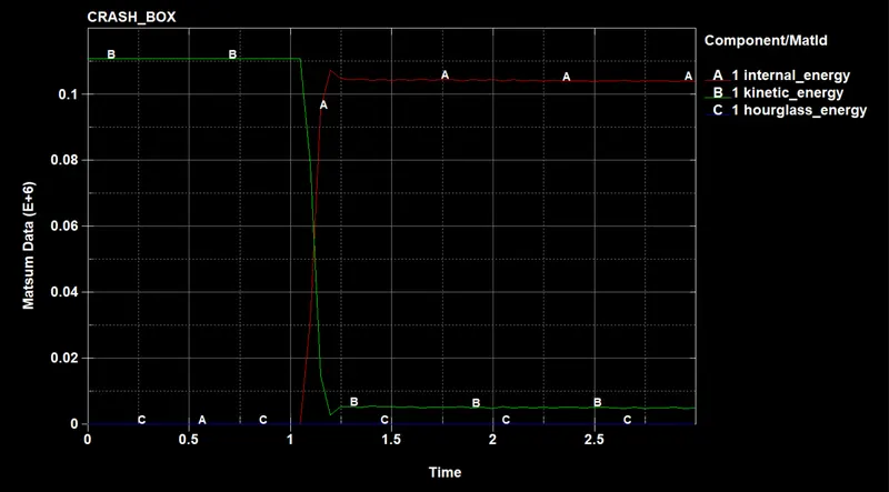
GLSTAT:
MATSUM:
NODOUT:
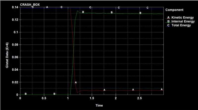
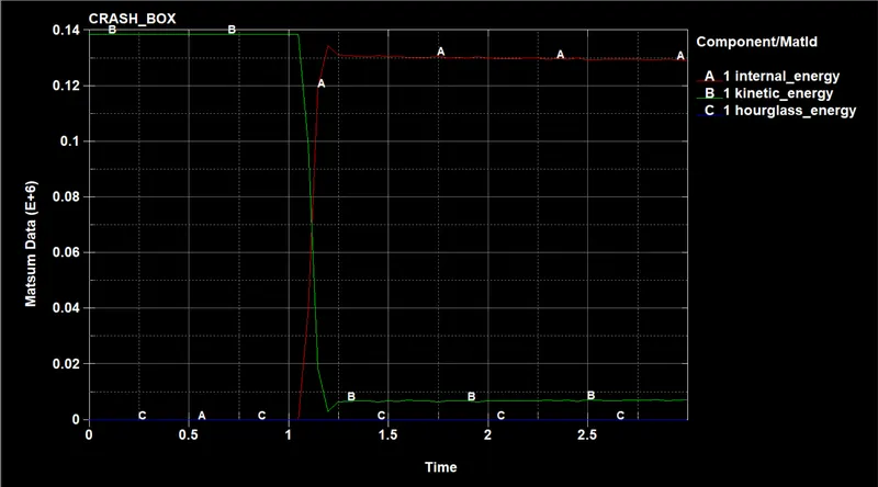
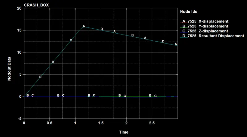
Plots for 1.5mm thickness:
GLSTAT:
MATSUM:
NODOUT:
Acceleration plot of a node for 1.2 mm:
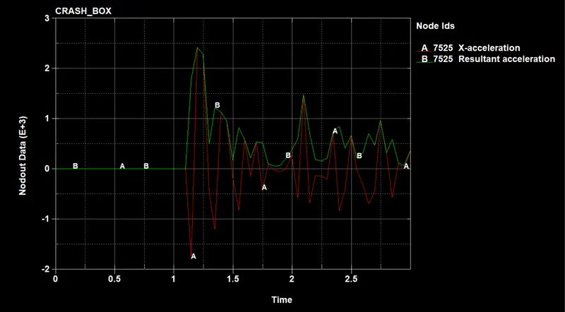
Acceleration plot of a node for 1.5 mm:
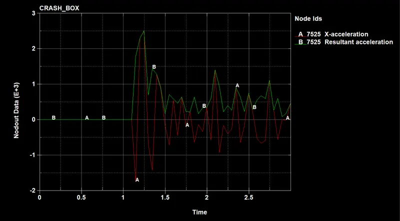
Directional stress and strain:
STRESS:
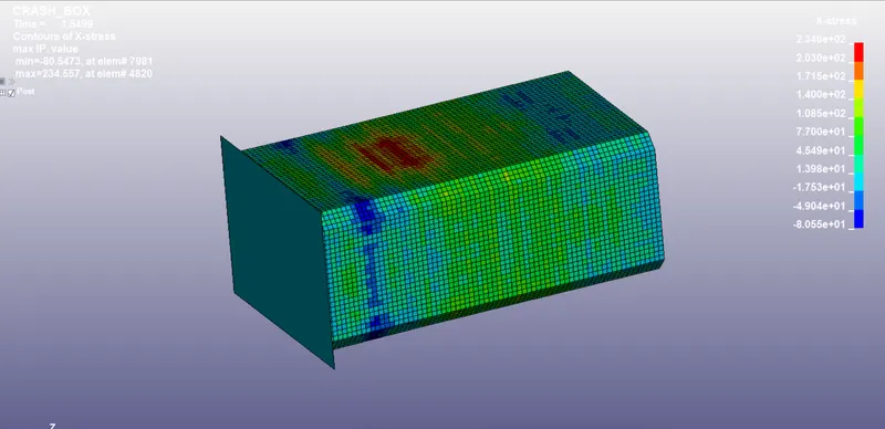
Maximum directional stress in the x-direction for the crash box having 1.2 mm thickness
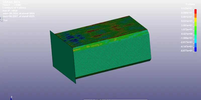
Maximum directional stress in the Y-direction for the crash box having 1.2 mm thickness
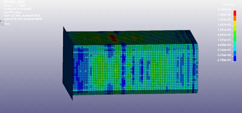
Maximum directional stress in the x-direction for the crash box having 1.5 mm thickness
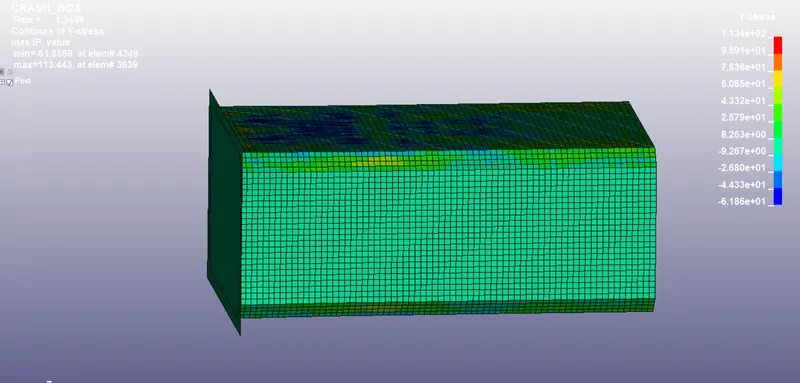
Maximum directional stress in the Y-direction for the crash box having 1.5 mm thickness
Conclusion:
Crashbox simulation is done successfully with 1.2mm and 1.5mm thicknesses respectively. All the objectives are fulfilled. From comparing the plots and animations we can say that simulation results will change as the thickness of the model changes.