Week - 4 - Crash Box Simulation
Introduction
A crash box is a highly energy-absorbing structure that crashes on the application of loads and reduces the impact on other components nearby. A full-fledged crash box is a highly sophisticated design but in this case, we will go with a rectangular channel which can be thought of as the most simple crash box.
- The crash box should crash into a rigid wall created using the *RIGIDWALL_ keyword.
- Material for the crashbox is steel.
- The simulation needs to be started using elastic material to verify its correctness and later a nonlinear material card data will be provided.
- Thickness of the crashbox is 1.2mm.
- Initial velocity for the crashbox should be around 50 kmph
- The units system to be used is gm-mm-ms
procedure to Import model
to import the model into the LS pre post gui we need to import dot k file from the drive.
click on file>click on import and select the dotk file
CREATE RIGID WALL
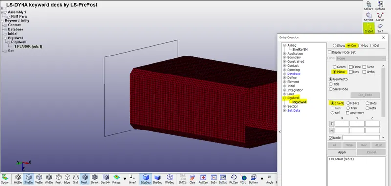
click on create entity>select the planer>select In+NL>select a node as shown in the snap below.
now click on tran option from the same window and translate 45mm in the direction of -ve x
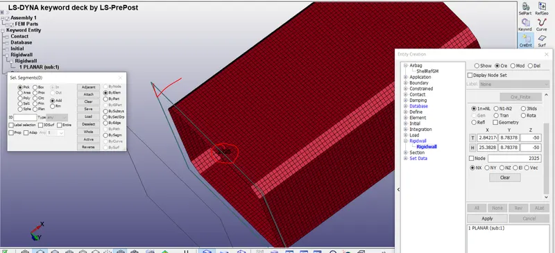
from the fig 2 the rwall has been moved almost 45mm in -ve x direction as shown in the below image
Intial velocity
to assign the intial velocity to the crash box we need to create node set id first therefore we have to click on create entity and click on setdata>click on NODE SET and select all the nodes of crash box .
Now set the name/title as NSET-INVEL as shown in below snap
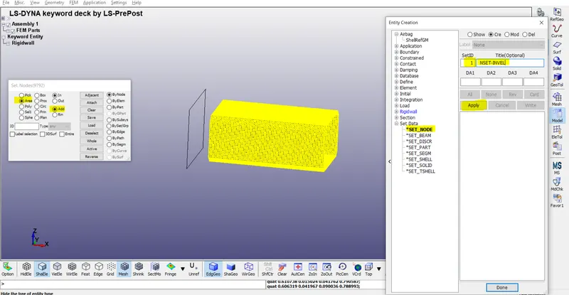
from the above image we have created node set id ,now we are able to give intial velocity to the crash box
click on keword manager select INTIAL >select VELOCITY
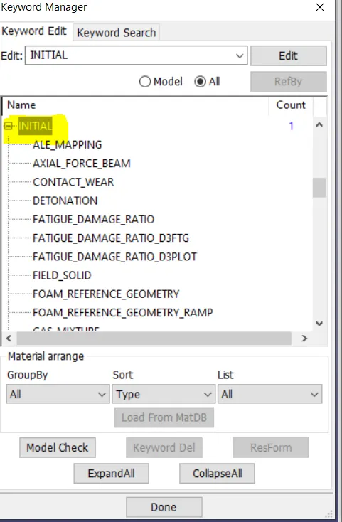
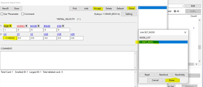
now we need to click on NSID a window will open just like the right side of the below image
we need to select the node set ID here that we have already created and velocity of 50kmph.
here we need to convert the velocity in mm/ms =50*5/18=13.88m/s
=13.88*1000mm/1000ms
=13.88mm/ms
once we set the data we need to accept and click on done
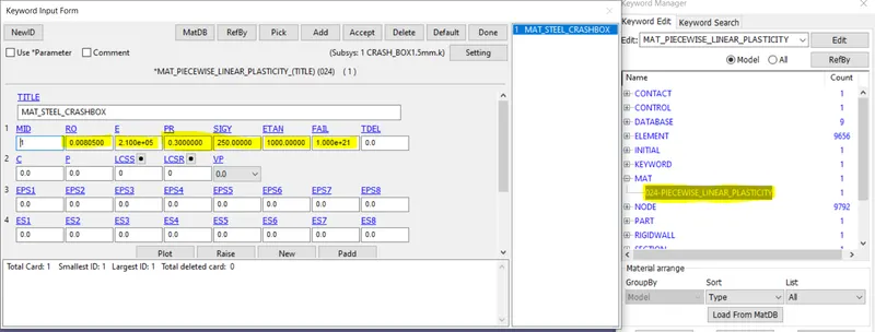
Ceate material card
To assign the thickness and element formulation
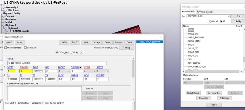
click on keyword manager >click on section >click on SHELL a window will open as shown in below snap
set the title name as SHELL_THICK _ELFORM
SET ELFORM=2
SHARE FACTOR=1
NO OF INT POINT=2
THICKNESS T1=1.2mm
CREATE A SECTION
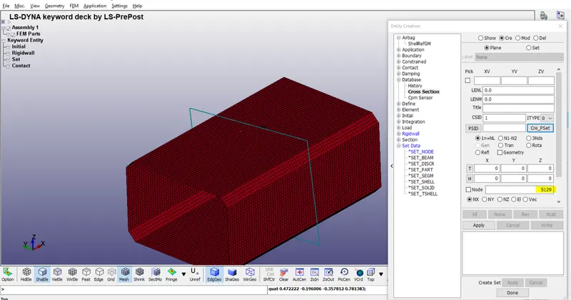
the section can be used to know the stress distribution or sectional forces that are being generated in the crash box
CLICK ON CREATE ENTITY >CLICK ON PLANE>SELECT A NODE ON THE SURFACE OF CRASH BOX >CLICK ON APPLY
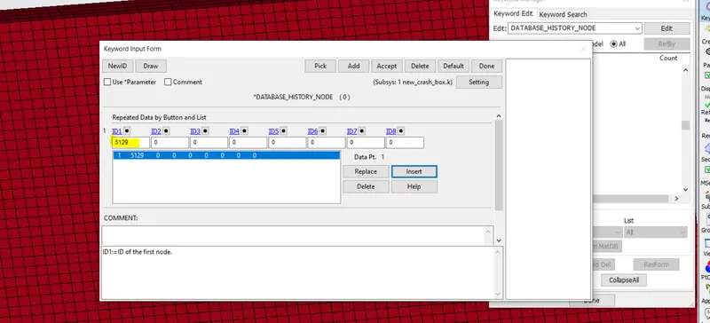
create database history node
we need to create a history of the node so that we can analyse the displacement acceleration of that particular node.
click on keyword manager >go to database >select history node a window will open as shown in below snape
in ID1 select a particular node on the surface of crash box and click non insert>click on accept >click on done
OUTPUT BLOCK REQUEST
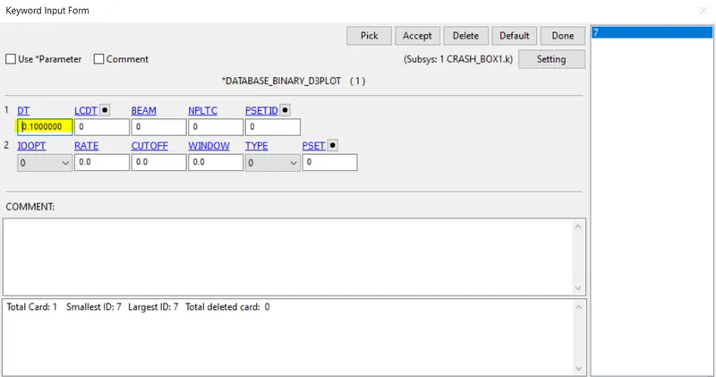
we need to create the D3PLOT these plots can be created on every time step
we have set DT=0.1ms
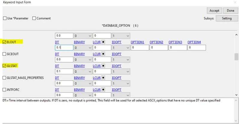
ASCII PLOT
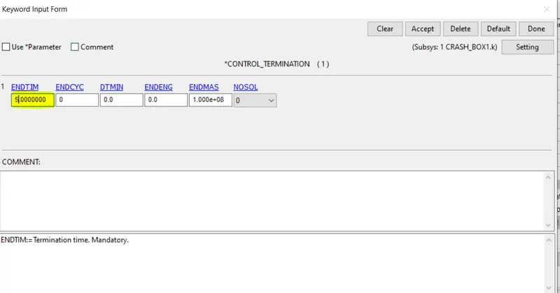
CONTROL TERMINATRION
collision distance = 45mm
initial velocity = 13.889 mm/ms
Time of collision = 45/13.889 ms
Time of collision = 3.24 ms
at 3.24 the crash box is going to impact with the rigid wall and after 3.24 ms the crash box is going to rebound after hiting the rwall so we need extra time for that to visualise the results properly
Total time = 3.24 + some for simulation to happen.
So total termination is to happen after 5ms
Termination = 5ms
now we are going to run the simulation
procedure to run simulation >click on file >click on Run ls dyna a command window will open just like below
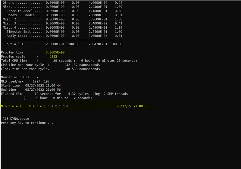
Case 2
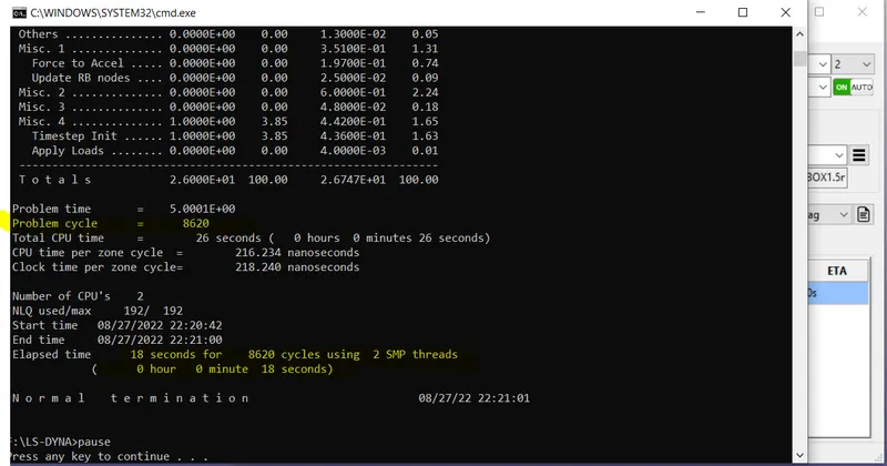
Results
as we have set the distance between the crash box and rigid wall to 45mm , at a velocity of 13.88mm/ms the crash box is going to hit the rwall at exactly 3.24 mili sec and then come back at a certain velocity.
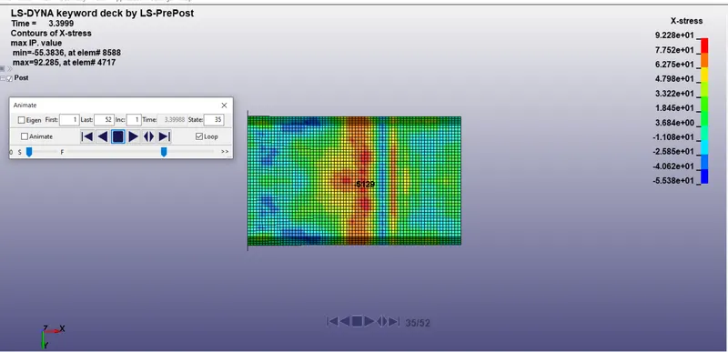
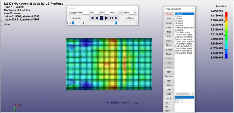
in both the cases as shown in below image the crash takes place at 3.24ms and the stress in the x-direction can be visualized using the X-stress contour plots .It can be seen the stress induced in the 1.5mm crash box is more than that of 1.2mm this is due to the higher mass occupied in the 1.5mm thick crash box.It is obvious that if any component possesses higher mass then it will have higher kinetic energy.
shell thickness 1.2mm
shell thickness 1.5mm
Global energy Data for 1.2mm & 1.5mm
shell thickness 1.2mm
the energy possessed by crash box (1.5mm) is more than that of 1.2mm because 1.5mm thick shell is going to occupy more mass than 1.2mm and more kinetic energy thus we can say more the kinetic energy more will be the stress, strain,plastic deformation etc this can be clearly seen in the below images.
shell thickness 1.2mm
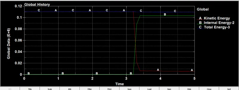
Fig-1
shell thickness 1.5mm
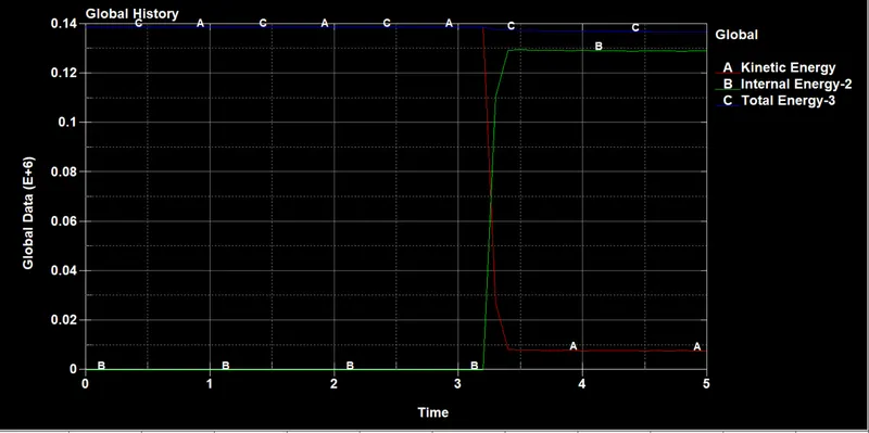
Fig-2
From the above two plots the crash box having a thickness of1.5mm possesses high kinetic energy
the kinetic energy remanins constant upto 3.24ms once the crash box impacts the Rigid wall the kinetic energy suddenly drops and the energy that is going to be stored in the form of internal energy has significant rise after hiting the rigid wall as shown in the green line
Rigid wall forces
the rigid wall forces can be seen higher in the 1.5mm because it posses high kinetic energy and also the higher momentum is also higher as compared to 1.2mm crash box.
when the crash box is going to hit the rigid wall at a higher moment the rigid wall is going to exert more resistive force to the crash box.
from the below plots it can be clearly seen the rigid wall forces is more in 1.5mm thick shell crash box because of higher mass higher KE and higher momentum
the maximum rigit wall forces is at 3.30 ms and was recorded 1.86e6 for 1.5mm and 1.5e6 for 1.2mm crash box
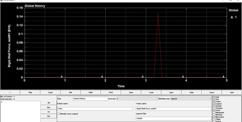
1.2mm
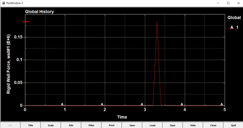
1.5mm
Nodal displacement
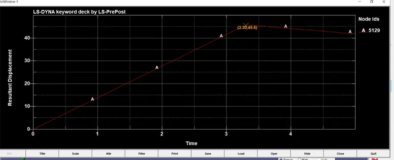
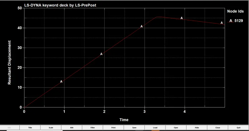
since the distance between the rwall and crash box is same for both the case (45mm).The same can be seen in the below image the node has a covered distance of 45mm but once the crash box hits the rigid wall the crash box is coming back due to resistive force being applied by R-wall ,thus the displacement gets decreased after impact.
ACCELERATION plot
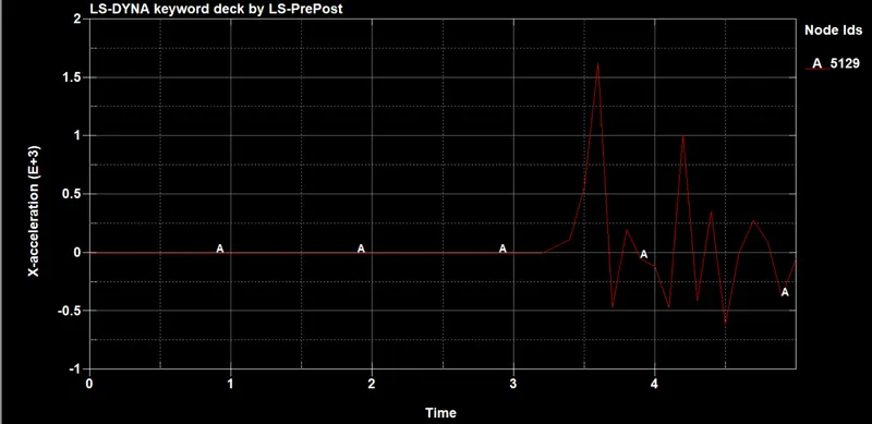
Acceleration along x direction
thickness =1.5mm
the acceleration of the node 5129 is maximum at 3.6 ms and is about 1.7E+03mm/ms2
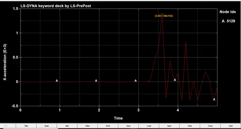
thickness=1.2mm
the acceleration of the node 5129 is maximum at 3.6 ms and is about 1.38E+03mm/ms2
The crash box has been simulated successfully and results are compared of both the cases
we conclude that more the shell thickness and more will be the momuntum, kinetic energy and more is the stress induce in the box