Week - 4 - Crash Box Simulation
CRASH BOX SIMULATION
AIM :- To study the Crash simulation of the Crash Box, crashing into a Rigid wall.
OBJECTIVE :- To simulate the given crash box (1.2 mm and 1.5 mm thick) onto a rigid wall at 50 kmph and obtain the following results.
Deliverables:
- Input.k file and output files (d3plot, glstat, sleout, rcforc).
- Animation of the final simulation.
- Cross-sectional force generated in the middle of the crash box (along its length).
- Acceleration plot of a node in the middle of the crash box (along its length).
- Maximum directional stress and strain along the length of the crash box (X strain, Y strain etc).
- Plot of all energies (total, internal, kinetic, hourglass, sliding).
- Compare the accelerations and stress/strain plots of 1.2/1.5mm crash boxes.
PROCEDURE :-
- Open LS-PrePost. Import crash_box.k file in LS-PrePost.
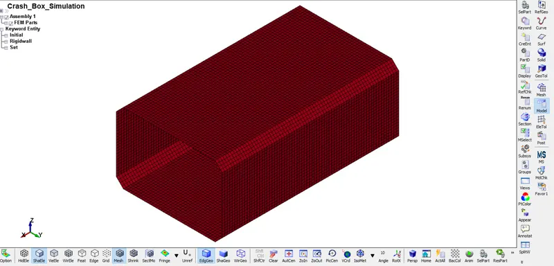
- Image 1: Imported Crash Box Model
- Then we need to give the contact and also, we need to apply the velocity to the whole Crash Box model.
- In the contact creation we need to make the Contact - Automatic - Single - Surface.
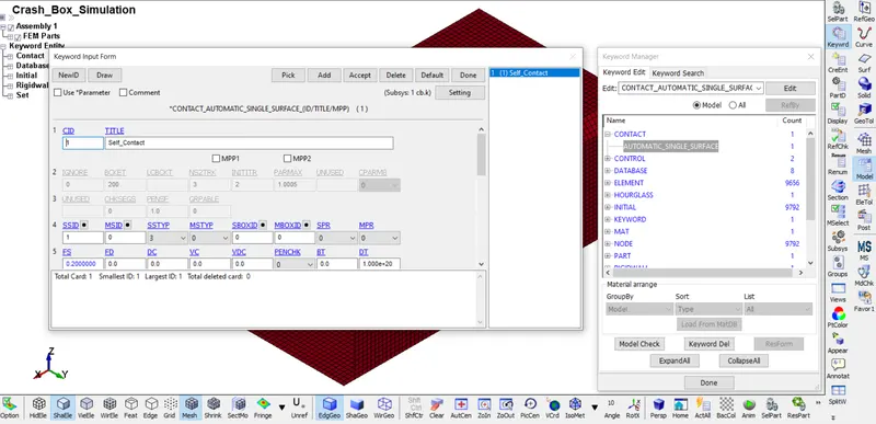
- Image 2: Contact Automatic Single Surface
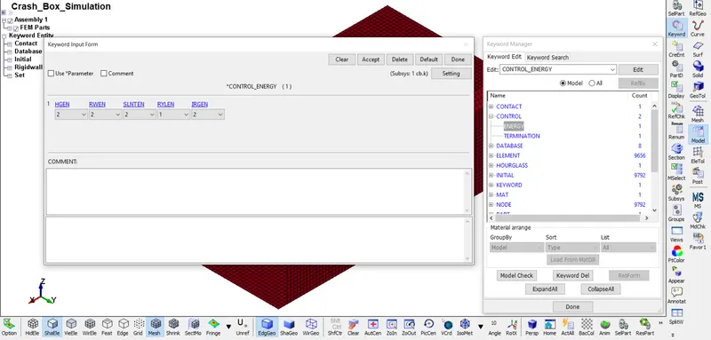
- Image 3: Control Energy Card
- Then we need to set control termination card, for that Model - Keyword Manager - Control - Termination - Set the total time of run.
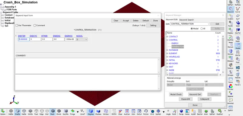
- Image 4: Control Termination Card
- Similarly, we can request for contact force d3plot, glstat, sleout, (RCFORC) etc in the database ASCII option card.
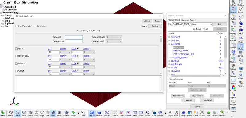
- Image 5: Database ASCII Option
- Since, we need to generate the plot of the energies of the simulation we need to request for it using the GLSTAT in Database ASCII keyword and set the DT which is the time interval in which the points on the plots are plotted.
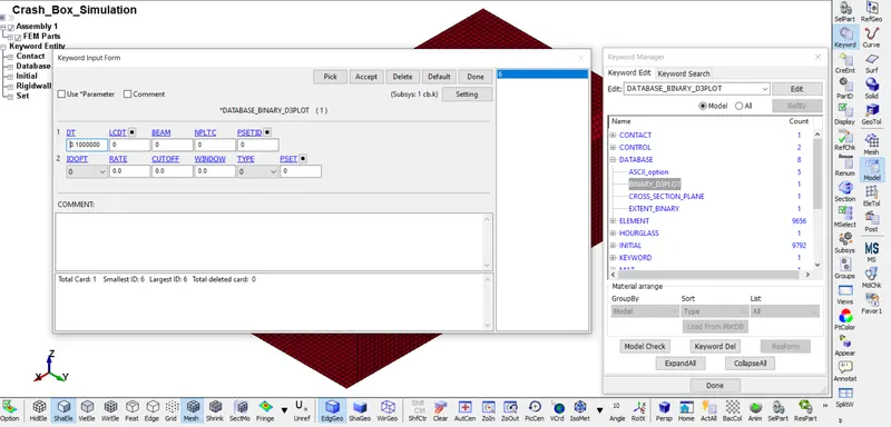
- Image 6: Database Binary D3PLOT
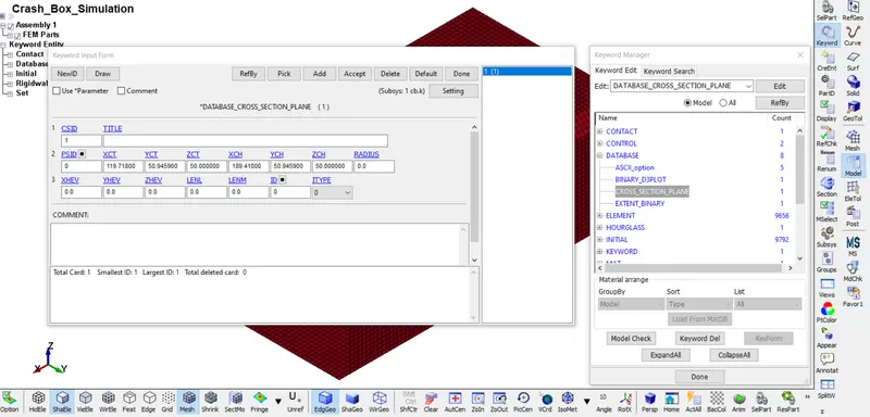
- Image 7: Database Cross Section Plane
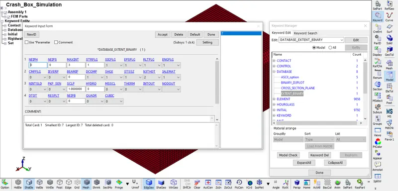
- Image 8: Database Extent Binary
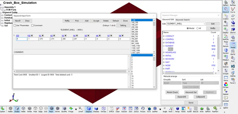
- Image 9: Element Shell
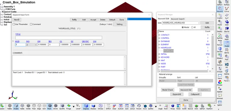
- Image 10: Hourglass Card
- Initial velocity has been assigned by using Initial - Velocity - Assign the Node Set Id - Give the Velocity as - the velocity is in negative X axis - Accept - Done.
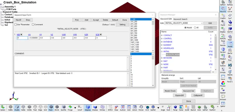
- Image 11: Initial Velocity Node Card
- In LS-DYNA there is no unit system, so in this project we have used unit system of gm, mm, ms ....... etc.
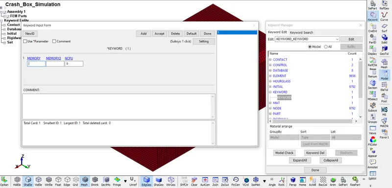
- Image 12: Keyword Card
- Steel material has been chosen for Crash Box material.
- Material card is created by using Model - Select Keyword - Choose MAT Keyword - Open MAT (001) card - select the Crash Box - Input the values of Density (Rho), E, Etan and Poison's Ratio (PR) in that card - Accept - Done.
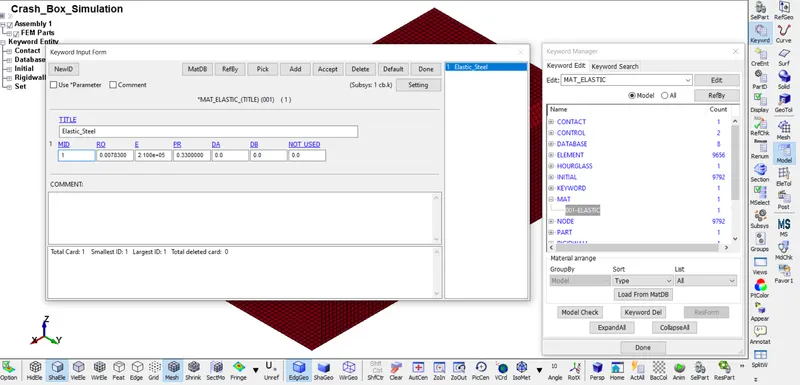
- Image 13: MAT 001 Elastic Card
- Nodes has been selected by using model - Keyword Manager - Node card - Select particular part - Accept - Done.
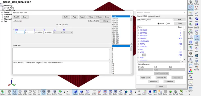
- Image 14: Node Card
- To define part id's Model - Keyword Manager - Assign Part - Assign PID and SECID - Accept - Done.
- This way we can create the part set for Crash Box.
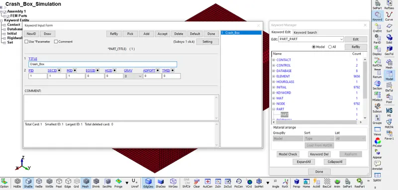
- Image 15: Part Card
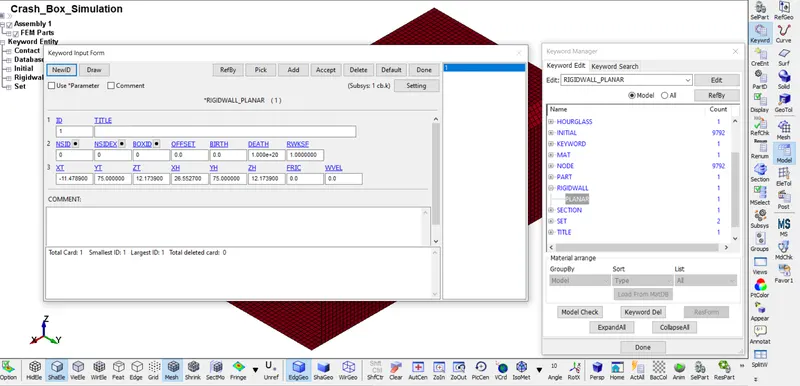
- Image 16: Rigid wall Planar Card
- Here, we need to create a section for Section Shell. we need to define section for Crash Box.
- Model - Keyword - Section - Shell - Accept - Done.
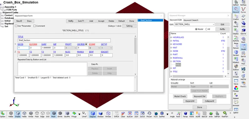
- Image 17: Section Shell Card
- NODESET id created on crash box to assign the velocity.
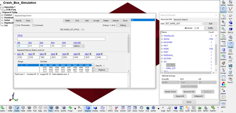
- Image 18: Set Node List Card
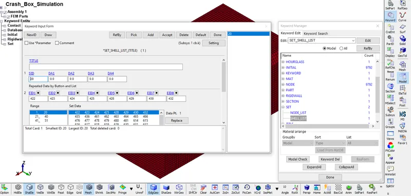
- Image 19: Set Shell List Card
- Title of this project given as Crash Box Simulation by using Title card.
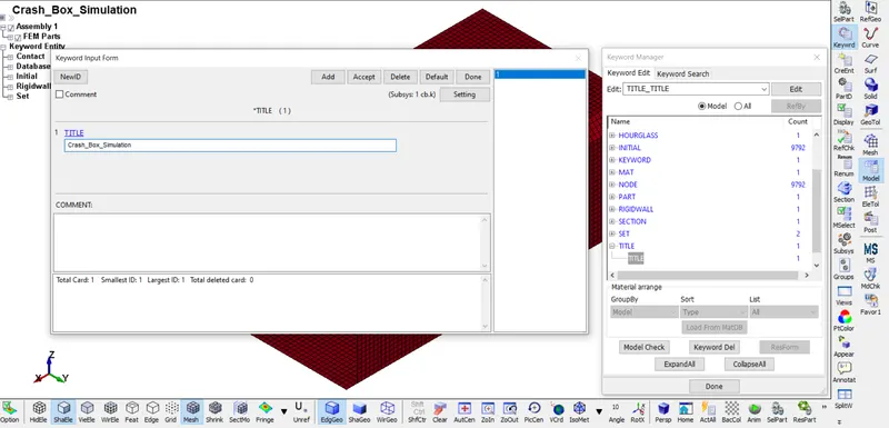
- Image 20: Title Card
RESULTS =
- Open new LS PrePost - File - Open Binary Plot - Select the d3plot file of Crash_Box_Simulation - open. This will show up the simulation in the LS PrePost.
- Select Fringe component tool on side tool bar - Select stress - Choose Von Mises Stress - Apply.
- This will show the Von Mises Stresses stress contour of the simulation.
POST-PROCESSING :-
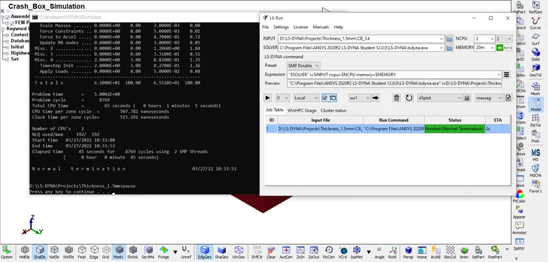
- Image 21: Normal Termination
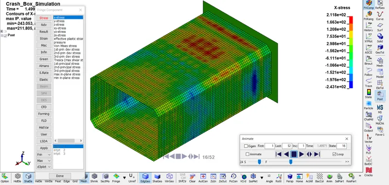
- Image 22: X-Stress
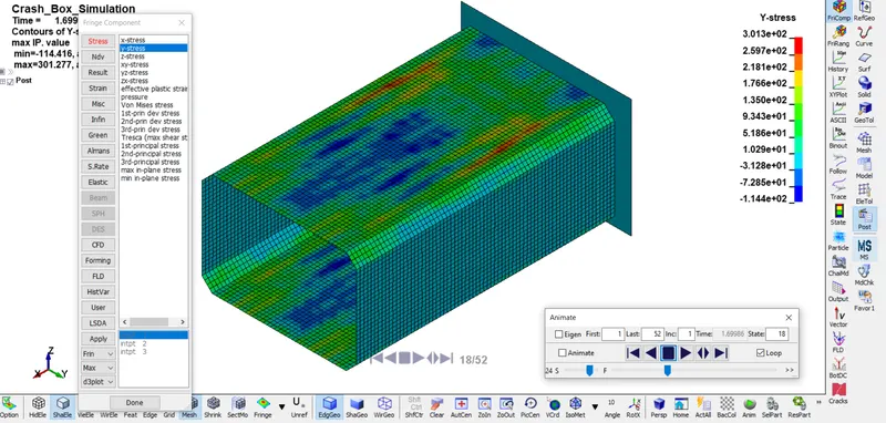
- Image 23: Y-Stress
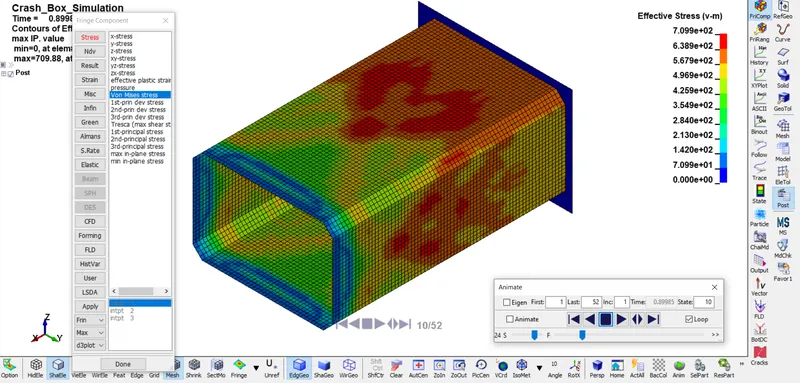
- Image 24: Von Mises Stress
Comparison of 1.2 mm and 1.5 mm Thickness Component :-
- The 1.5 mm thickness crash box is deformed less when compared with 1.2 mm thickness crash box.
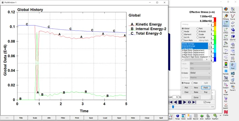
- Image 25: Energy plot for 1.2 mm thickness
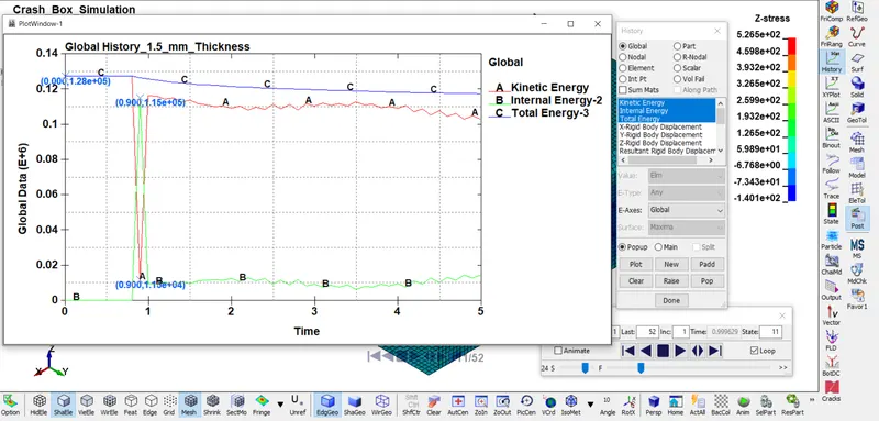
- Image 26: Energy plot for 1.5 mm thickness
CONCLUSION :-
- Crash Box hitting on a rigid wall has been simulated and results have been discussed. From this challenge I learned about the process of setting up the solver deck for the Crash Box simulation.