Week - 4 - Crash Box Simulation
AIM:
To simulate a crash test for a crash box for which mesh is given.
Assumptions and information required:
- The crashbox should crash into a rigidwall created using *RIGIDWALL_ keyword. Check the manual to understand and create a rigidwall.
- Material for the crashbox is steel. The simulation needs to be started using elastic material to verify its correctness and later a nonlinear material card data will be provided. Thickness of the crashbox is 1.2mm.
- Initial velocity for the crashbox should be around 50 kmph
- The units system to be used is gm-mm-ms
- The simulation should satisfy either of the two situations - (1) It crashes on the rigidwall and rebounces completely or (2) it buckles and folds in the axial direction so as to come in self-contact.
- Once the simulation is completed and results as asked for below is collected, run another simulation by increasing the thickness of the crashbox from 1.2 to 1.5mm.
- Input .k file and output files (d3plot, glstat, sleout, rcforc)
- Animation of the final simulation
- Cross-sectional force generated in the middle of the crashbox (along its length)
- Acceleration plot of a node in the middle of the crashbox (along its length)
- Maximum directional stress and strain along the length of the crashbox (X strain, Y strain etc)
- Plot of all energies (total, internal, kinetic, hourglass, sliding)
- Compare the accelerations and stress/strain plots of 1.2/1.5mm crashboxes.
THEORY:
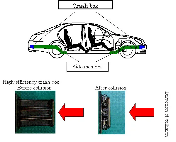
A crash box is a highly energy absorbing structure that crashes on application of loads and reduces impact on other components nearby. A full-fledges crashbox is a highly sophisticated design but in this case we will go with a rectuangular channel which can thought of as the most simple crashbox.
PROCEDURE:
Import the .K File into LS-PREPOST:
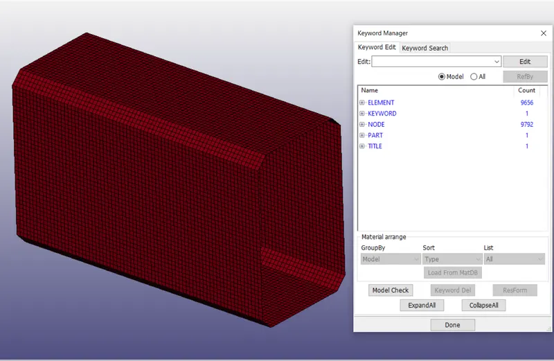
We can see only the parts are defined in the keyword manager.
Steps to follow:
1. Change the Title
2. Create a material card
3. Create the Section card
4. Assign the material and section to the parts
5. Create the rigid wall
6. Create the velocity card
7. Create the sectional force card
8. Create the control energy card
9. Create the Control Termination card
10. Request for the Database cards
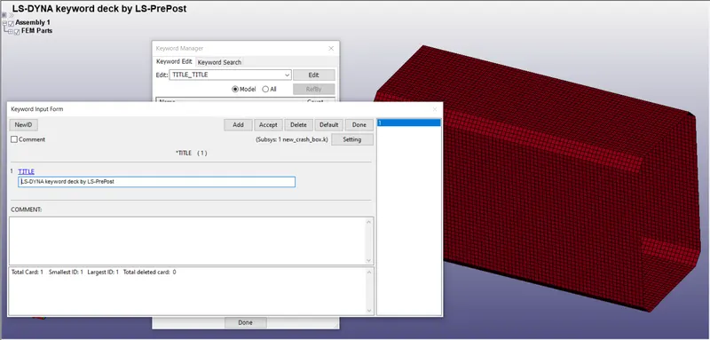
Step 1: Change the Title
Go to keyword manager >>> Title
Step 2: Create a material card
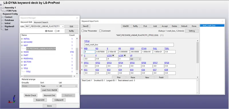
We have to create the material for the parts given. Steel is considered in this case
Density = 0.0078 gm/mm^3
Youngs modulus = 210000 MPA
Poissons ratio = 0.3
Maximum stress = 350 MPA
Step 3: Create the Section card
A Section card is defined for every part to provide the element formulation
ELFORM = 2 is used. (Belytschko-Schwer resultant beam)
The thickness = 1.2 mm is provided
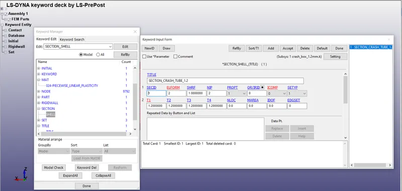
The thickness = 1.5 mm is to be provided by creating a new card.
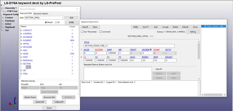
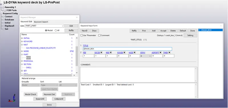
Step 4: Assign the material and section to the parts
We have to assign the sections and materials created to the respective parts as shown below.
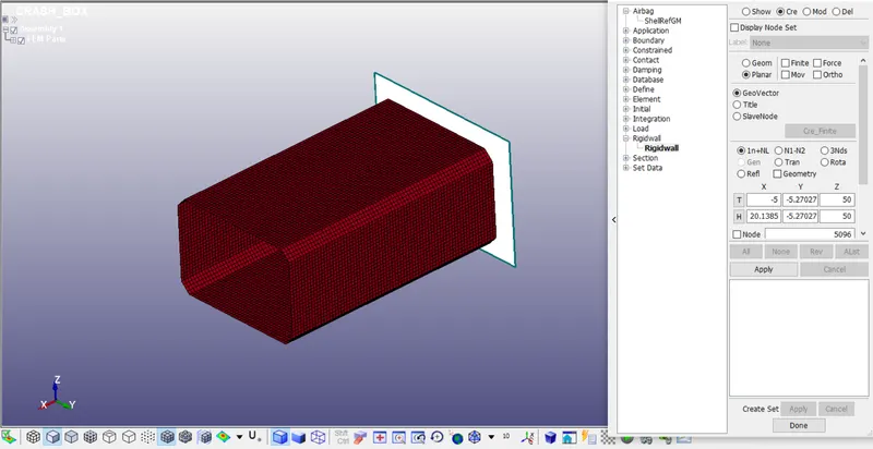
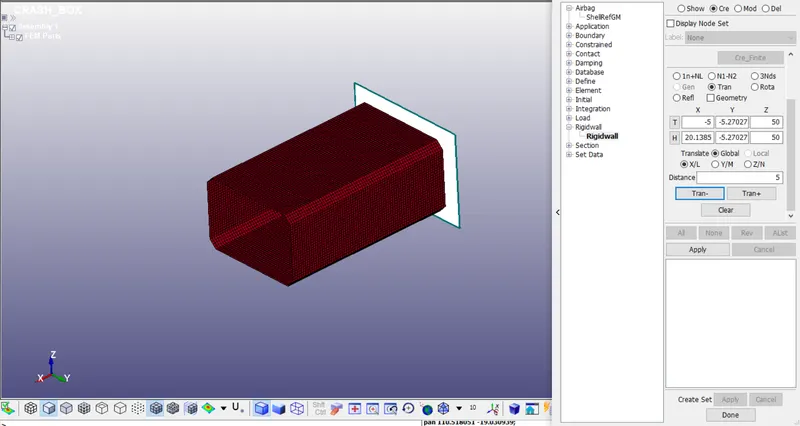
Step 5: Create the rigid wall
Go to create entity >>> Rigidwall >>> Create >>> Planar >>> By nodes >>> translate global and provide some gap.
Step 6: Create the velocity card
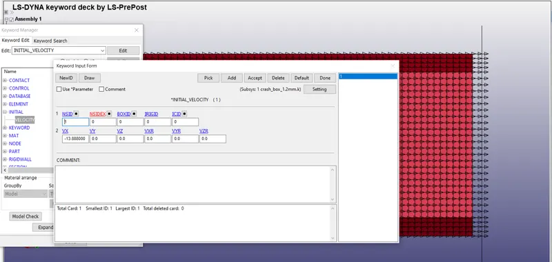
Go to keyword manager >>> All >>> Initial >>> Velocity
Create the node-set for the whole crash box and assign it as NSID
Provide the velocity for the crash box towards the rigid wall
V = -13.888 mm/ms
Step 7: Create the sectional force card
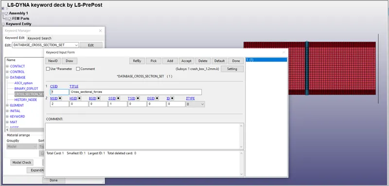
Create the node-set and Shell element set at the middle of the crash box.
Enable the Database_Sectional forces and assign the NSID and SSID to the card.
Step 8: Create the control energy card
To consider the Hourglass energy, Sliding energy, Rigid wall energy, we have to activate the respectives in the Control_Energy card.
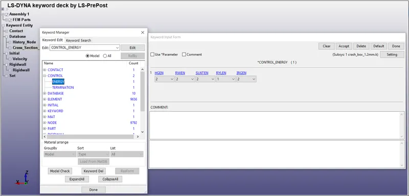
HGEN: Hourglass energy is computed and included in the energy balance.
RWEN: Rigid wall energy dissipation is computed and included in the energy balance.
SLNTEN: Sliding interface energy is computed and included in the energy balance
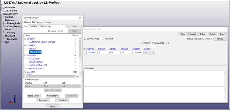
Step 9: Create the Control Termination card
Control_Termination card is to be provided to specify how much time this simulation has to run.
Step 10: Request for the Database cards:
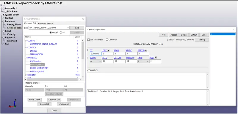
Request for D3PLOT:
DT = 0.2 :Time interval at which the animation files should be printed.
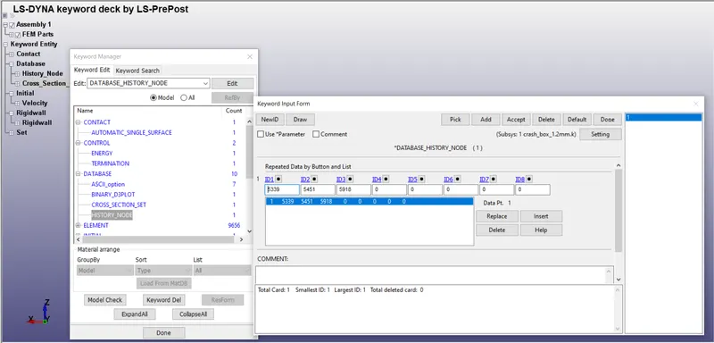
Create a node set ID By choosing random three nodes at the middle of the crash tube.
Go to Database_History_Node >>> Select the nodes >>> Done
History node is used to study the accelaration, velocity and displacement at a particular node.
In Database_Ascii >>> Activate GLSTAT, ELOUT, MATSUM, NODOUT, SWFOR, SLEOUT, SECFORC
GLSTAT: GLOBAL DATA
ELOUT: ELEMENT DATA
MATSUM: NATERIAL ENERGIES
SLEOUT: SLIDING INTERFACE ENERGIES
SECFORC: SECTIONAL FORCES
NODOUT: NODAL POINT DATA
SWFORC: SHEARWALL FORCE
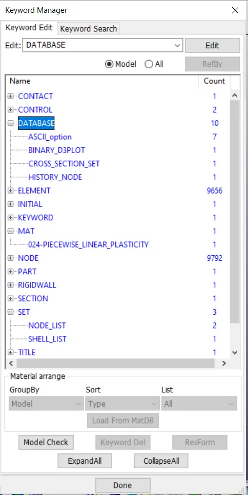
Keywords used:
Explaining the deliverables:
Von-mises STRESS 1.2mm:
We import the Binary D3 plot.
Go to Post-proccesing >>> Fringe component >>> Stress >>> Von-mises >>> Plot
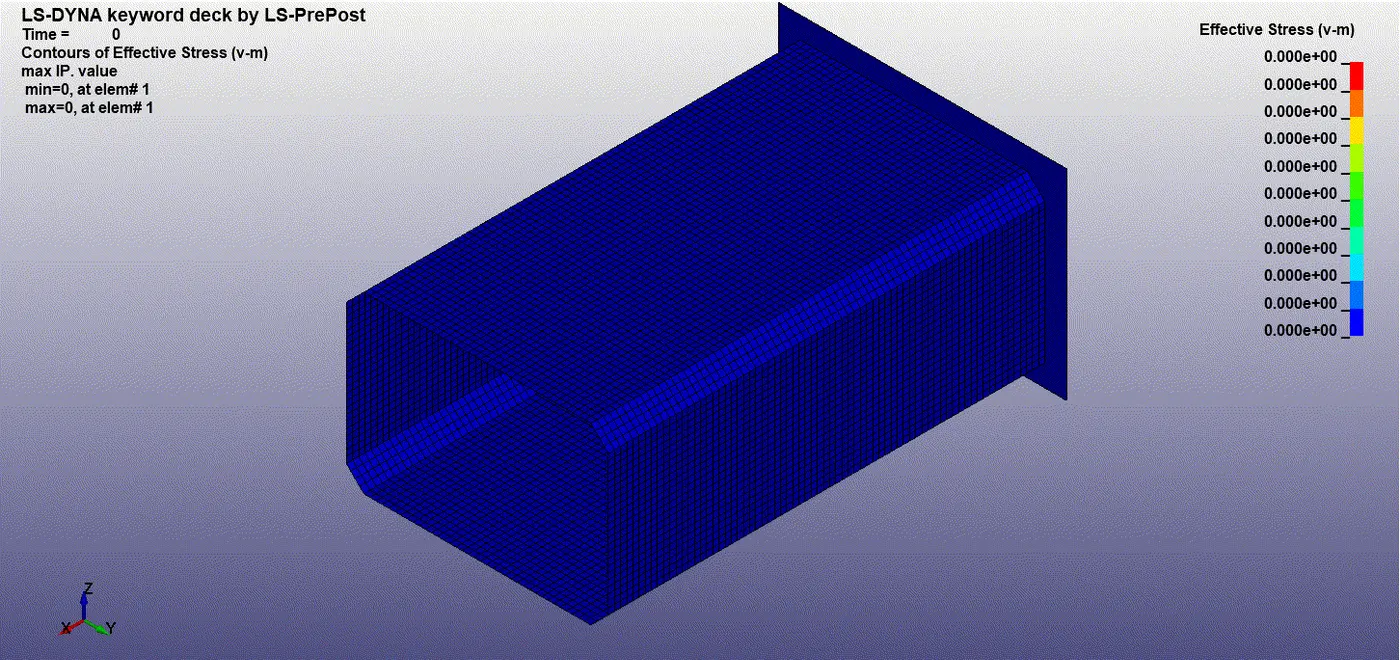
Maximum stress during impact = 430.4 MPa at node Id = 9523.
Von-mises 1.5mm:
Maximum stress during impact = 429.49 MPa at node Id = 9523.
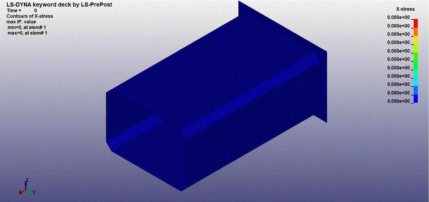
X-Stress 1.2mm:
The maximum x-stress is seen during the impact = 426.3 MPa.
X-stress 1.5mm:
The maximum x-stress is seen during the impact = 393.9 MPa.
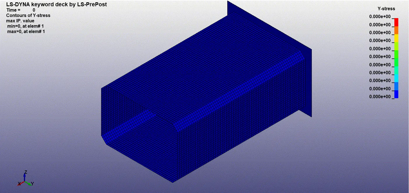
Y-stress 1.2 mm:
The maximum y-stress is seen during the impact = 407.2 MPa.
Y-stress 1.5 mm:
The maximum y-stress is seen during the impact = 336.9 MPa.
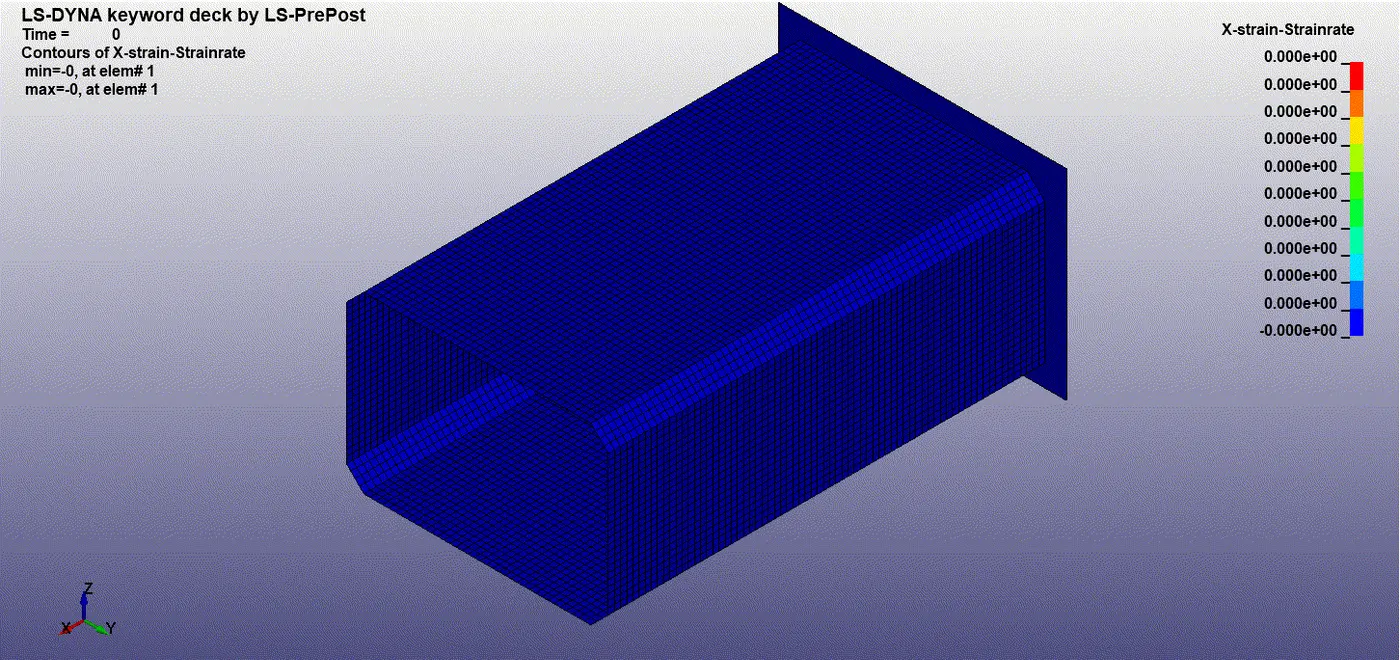
X-strain 1.2 mm:
The maximum x-strain rate is seen at element number 1628: 0.8878.
X-strain 1.5mm:
The maximum x-strain rate is seen at element number 1628: 0.9047
Y-strain 1.2 mm:
The maximum y-strain rate is seen at element number 1628: 0.8878.
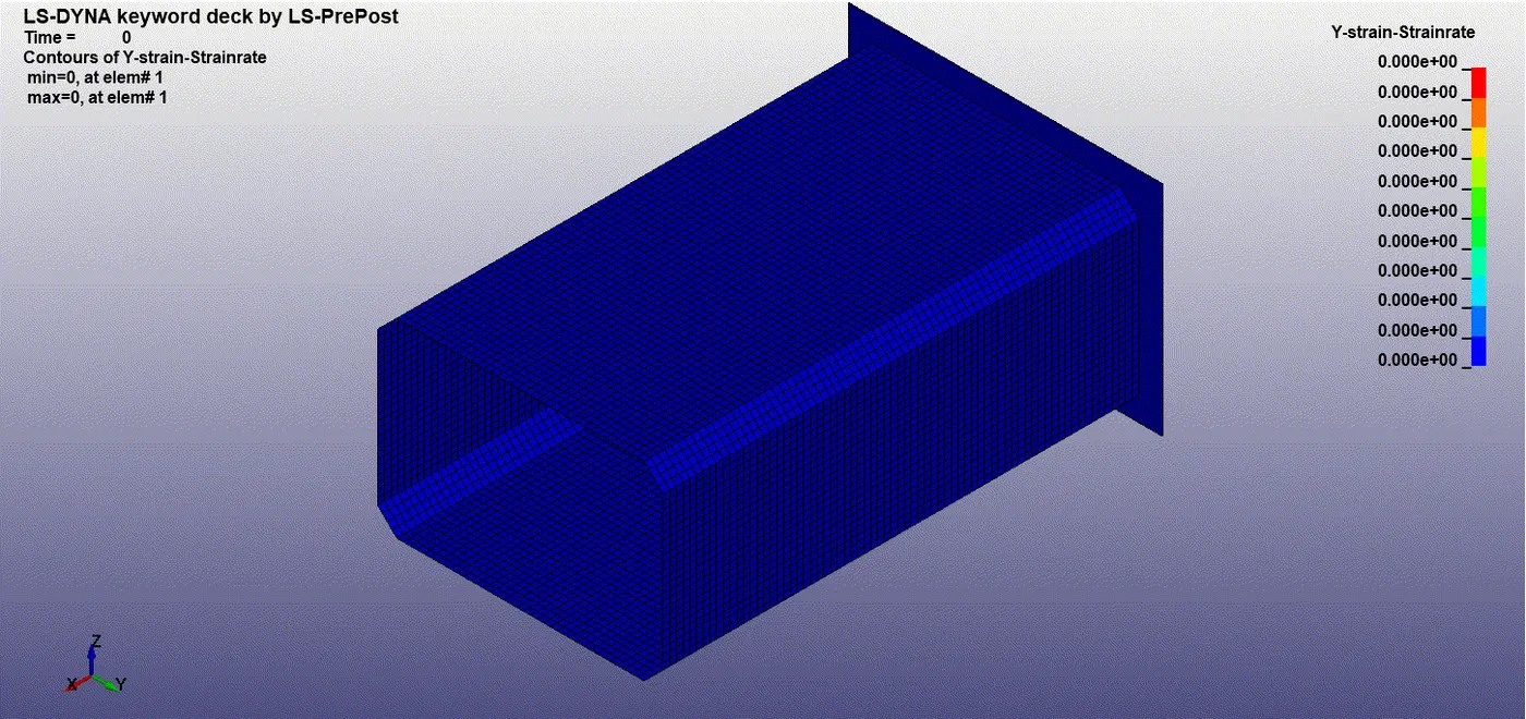
Y-Strain 1.5 mm:
The maximum y-strain rate is seen at element number 3079 : 0.11872.
Plotting:
We plot the energies, Sectional forces, Nodal acceleration using post-processing
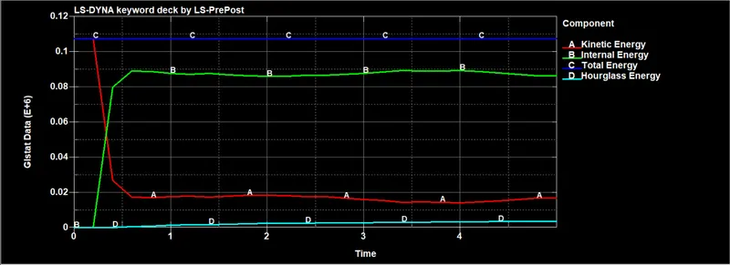
Global data is plotted as shown below, which consists of internal energy, kinetic energy, hourglass energy, total energy.
We can see as soon as impact happens the kinetic energy due to the initial velocity gets decreasing there by increasing the internal energy.
The hourglass energy is almost neglicible when compared with the total energy.
The total energy is constant through out, because of decreasing kinetic energy and increasing internal energy.
Crashbox 1.2mm:
Maximum Internal energy = 0.09 E+6 kJ
Maximum Kinetic energy = 0.108 E+6 KJ
Maximum Total energy = 0.108 E+6 KJ
Maximum Hourglass energy = 0.003 E+6 KJ
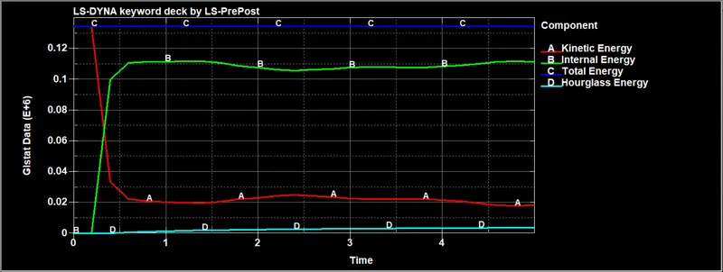
Crashbox 1.5mm:
Maximum Internal energy = 0.11 E+6 KJ
Maximum Kinetic energy = 0.134 E+6 KJ
Maximum Total energy = 0.134 E+6 kJ
Maximum Hourglass energy = 0.003 E+6 KJ
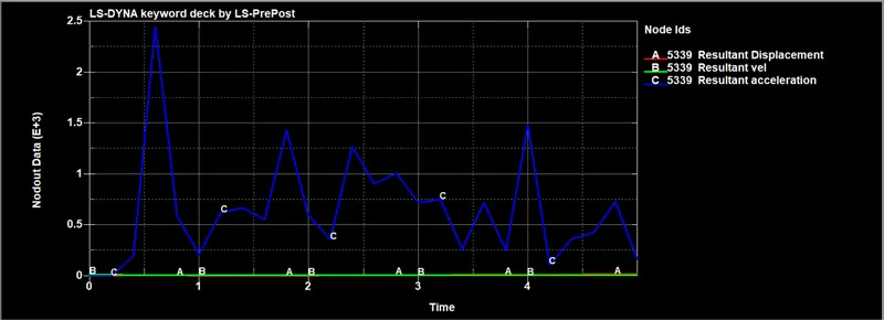
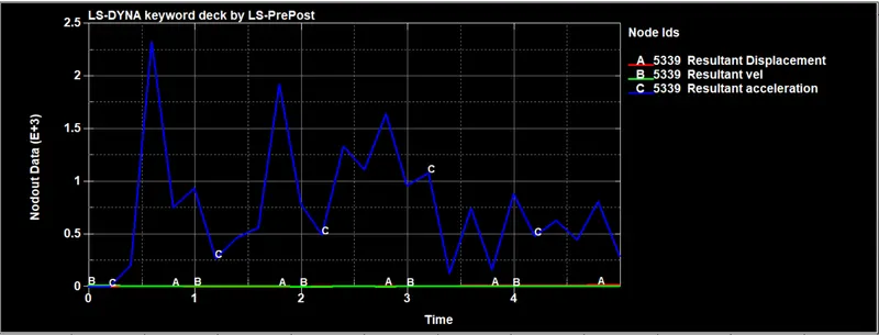
Crashbox 1.2mm
PEAK ACCELERATION during impact = 2.45 mm/ms^2
Crashbox 1.5mm
PEAK ACCELERATION during impact = 2.3 mm/ms^2
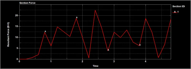
Sectional forces in the cross section:
Crashbox 1.2mm:
Peak force due to impact = 25 KN.
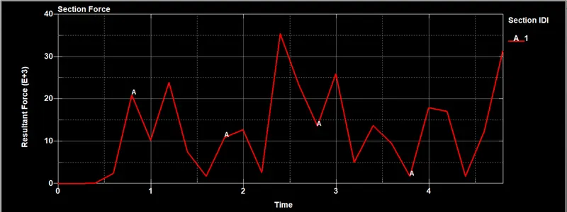
Crashbox 1.5mm:
Peak force due to impact = 35 KN.
COMPARISON:
GLOBAL DATA OF CRASH BOX:
| ENERGY | 1.2 mm | 1.5 mm |
| Internal Energy | 0.09 E+6 KJ | 0.11 E+6 KJ |
| Kinetic energy | 0.108 E+6 KJ | 0.134 E+6 KJ |
| Total Energy | 0.108 E+6 KJ | 0.134 E+6 kJ |
| Hourglass Energy | 0.003 E+6 KJ | 0.003 E+6 KJ |
We can see that the internal energy in 1.5mm Crash box is more than in the 1.2 mm crash box. This shows that the box with 1.5mm thickness can absorb more energy.
We can see hourglass energy is well below 15% of the total energy, This is due to fully integrated formulation of elements.
DIRECTIONAL STRESS AND STRAIN:
| DIRECTIONAL STRESS AND STRAIN | CRASH BOX 1.2mm | CRASH BOX 1.5mm |
| X- directional Stress | 426.3 MPa | 407.2 MPa |
| Y- directional Stress | 393.9 MPa | 336.9 MPa |
| X- directional Strain | 0.8878 | 0.88780.9047 |
| Y- directional Strain | 0.9047 | 0.11872 |
the x-directional stress is more in the 1.5mm crash box because of applied initial velocity in that direction and thereby decreasing the acceleration which resulted in more stress.
Cross Sectional forces:
| CRASH BOX 1.2mm | CRASH BOX 1.5mm | |
| Cross sectional forces | 25 KN | 35 KN |
| Acceleration | 2.45 mm/ms^2 | 2.3 mm/ms^2 |
As we can see cross-sectional forces for crash box with 1.5mm thickness is more because of the extra mass of 1.5mm shell when compared to 1.2 mm shell.
It shows the peak acceleration is more in 1.2 mm shell compared to 1.5mm shell. we can see the acceleration values negative, this is because the crash box is stopped by a rigid wall and thus deccelerates. Whereas the resultant acceleration is the magnitude equal to x- direction acceleration value because acceleration in y & z direction are neglicible.
CONCLUSION:
From the results plotted we can conclude that the crash box with 1.5mm thickness is better than 1.2 mm thickness because the crash box with 1.5mm has more internal energy which absorbs more energy.