Week - 4 - Crash Box Simulation
CRASH BOX SIMULATION USING LS-DYNA
A crash box is a highly energy absorbing structure that crashes on application of loads and reduces impact on other components nearby.
OBJECTIVE:
- To check the cross-section force generated in the middle of the crashbox.
- Behavior of box after contact.
- Effect of different thickness on stress, energy, strain and acceleration of box.
Unit system followed here is gm-mm-ms.
In this challenge, crash box collide with rigid wall with initial velocity of 50km/hr i.e. 13.88mm/ms.
Procedure:
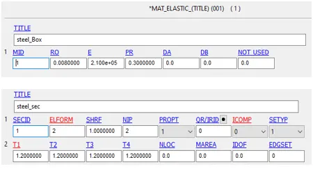
- First open the .k keyword file, After that assign material and section to the box. Here, elastic material is assigned to check the correctness of model.
- Elastic material properties like density, young's modulas, poision ratio is assigned.
- As this is a shell part, so shell section is assigned using section-shell with thickness of 1.2mm.2.
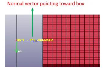
2. After that a planar Rigidwall is created using creEnt - Rigidwall - planar.
- wall is translated to certain distance like here is 20mm.
- Wall normal vector orientation is corrected, as it should point toward the object which is going to collide.
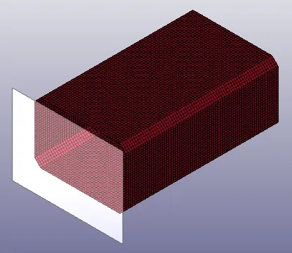
3. Then initial velocity is given to all the nodes of box. For that first a node set is created of all nodes and a velocity of 13.88mm/ms is given.

4. Here we need to give the automatic single suface contact because when box will strike the wall, there is chance of collision among the box elements. Box is given the slave id because it is the deforming part with slave set part ID 3.
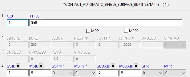
5. Now from the control keyword--
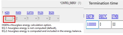
- Termination time is given 8ms.
- As here we need to calculate the hourglass energy so from control - energy - hourglass energy option is switched on by setting values to 2.
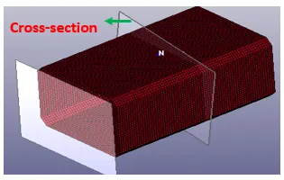
6. As we need to calculate the force at the centre portion of the box, so a cross-section is created using database - cross-section - node select.
7. Now complete model is set, we just need to give the output parameters that we want to calculate. Output parameters are
- Binary d3plot
- ASCII- GLSTAT - To calculate the global statistics and energies.
- ASCII- MATSUM - To calculate all material energies.
- ASCII- RCFORC - This is calculated but it will not show any output because there is no contact between two parts. It only works where a contact is present between two parts. Not work for single body contact.
- ASCII- SLEOUT - To calculate sliding interface energy.
- ASCII- SPCFORC - To calculate the force at cross section that we created above.
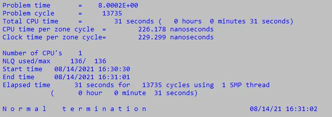
8. Now model is saved as .K file and simulation is run. Simulation took 31 sec to complete.
9. Results to check model correctness
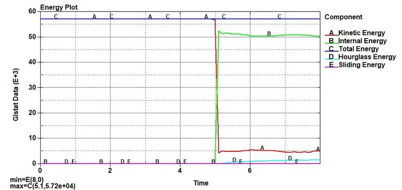
(a) Energy Plot - Here we can clearly see that model is converged, as kinetic energy is transforming into internal energy. Hourglass energy is very less.
Total energy is constant throughout which indicate that our model is correct. As we can see from plot at time 5 ms (time of impact) kinetic energy is converted into internal energy. Here strain is very less so hourglass energy is very less. Sliding energy is almost zero as no sliding is happening in model.
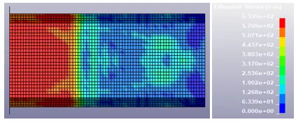
(b) Stress Contour at point of contact
Effect of thickness on stress, strain and energies :
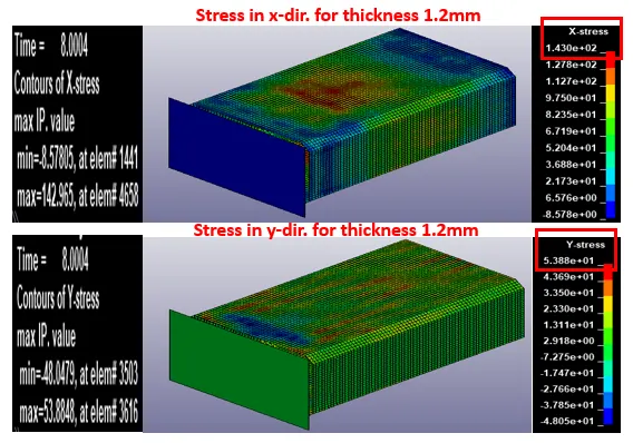
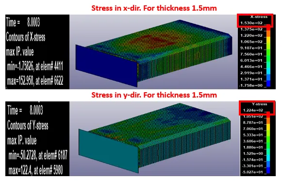
1. Comparison of stress in x and y dir. for thickness 1.2mm and 1.5 mm
From the below results we can see that stress in 1.5m thickness part is more in both x and y direction than 1.2mm thickness. As stress is force per unit area and force is mass*acceleration. Here before contact acceleration is constant for both cases. So box with heavy mass will produce more resistive force and correspondingly more stress.

Stress in t = 1.2mm box
Stress in t = 1.5mm box
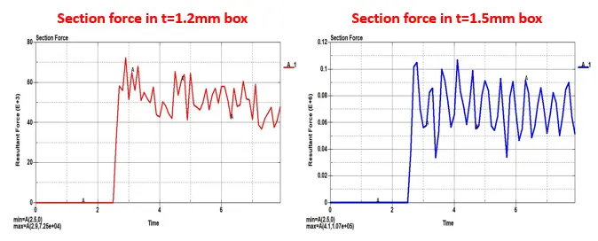
2. Comparison of Section force for thickness 1.2mm and 1.5 mm
As i explained above force in 1.5mm box is more than 1.2mm box.

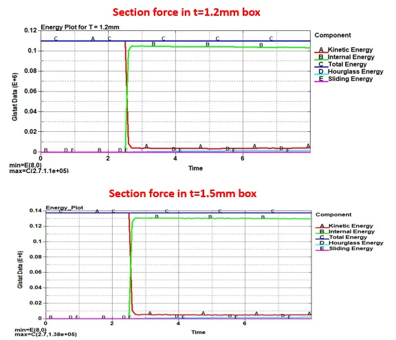
3. Energy plots
In both the cases, model is converged. Total energy remains constant. Kinetic energy is converted into internal energy. And hourglass and sliding energies are very less. More energy is generated in higer thickness part as absorbs more stress due to impact.
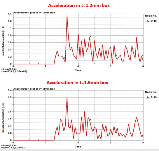
4. Acceleration plots
Middle element 5149 is selected. Here heavier box has less acceleration after impact.

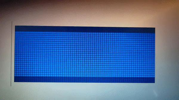
5. Animation
Conclusion:
1. More stress is generated in box with more mass i.e. 1.5mm. As stress is force per unit area and force is mass*acceleration. Here before contact acceleration is constant for both cases. So box with heavy mass will produce more resistive force and correspondingly more stress.
2. As kinetic energy is converted to internal energy and total energy remains constant throughout which indicate that model is correct.
Learning Outcomes:
1. How to model a crash box problem.
2. Which ASCII set is used for what purpose like secforc for calculating force at section, extent binary for strain tensor etc.