Week 4 - CHT Analysis on Exhaust port
Aim : To perform Conjugate heat transfer analysis on Exhaust port and justify the results.
Why and where a CHT analysis is used ?
- Conjugate heat transfer refers to the simultaneous heat transfer between solid surfaces and adjacent fluids (liquids or gases). It considers the interaction between conduction within solids and convection within fluids.
- Conduction within solids: Heat transfer occurs through the solid material by conduction. This involves the transfer of heat due to molecular agitation within the solid material itself.
- Convection within fluids: Heat transfer occurs through the fluid by convection. Convection can be either forced (due to external factors like pumps or fans) or natural (due to density differences within the fluid).
- Interfaces: At the interface between the solid and fluid, heat is exchanged between the solid surface and the adjacent fluid. This exchange involves both conduction into or out of the solid surface and convection of the fluid over the solid surface.
- Conjugate heat transfer analysis is important in many engineering applications where heat dissipation, thermal management, or energy efficiency are critical factors.
- It provides a more accurate results.
- Conjugate heat transfer has widespread applications in various engineering fields, including electronics cooling, thermal management of engines, and HVAC.
Procedure :
1. Import the geometry to the spaceclaim.
2. Extract the fluid volume by Prepare - Volume extract - Edges.
3. Combine the regions by box selecting the two volumes and share the region by Workbench - Share.
4. The shared region will be represented in pink color.
5. Move to mesh and give the three different mesh
i.) default mesh size
ii.) Mesh size - 10mm with inflation layer - 5, max thickness - 5mm
iii.) Mesh size - 5mm with inflation layer - 5, max thickness - 5mm
6. Go to setup section, check for materials Solid - Aluminum & Liquid - air.
7. Boundary Conditions:
Inlet, Velocity=5 m/s and the temperature=700 k.
For the outer wall, choose convection with Heat Transfer Coefficient=20 w/m^2.k
Outlet, pressure = 0.
8. Run hybrid initialization and move to results section create Temperature contour & Velocity contour.
9. Move to solution tab, run calculation for 500 iterations.
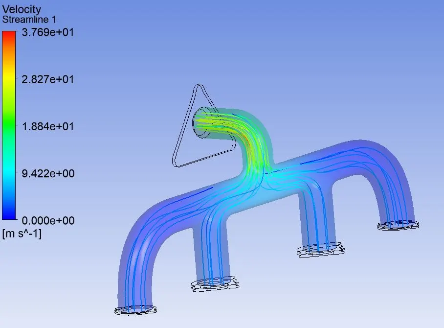
10. After 500 iterations, close the application and move to results create streamline velocity.
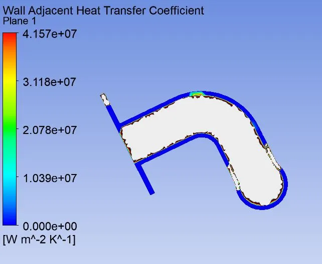
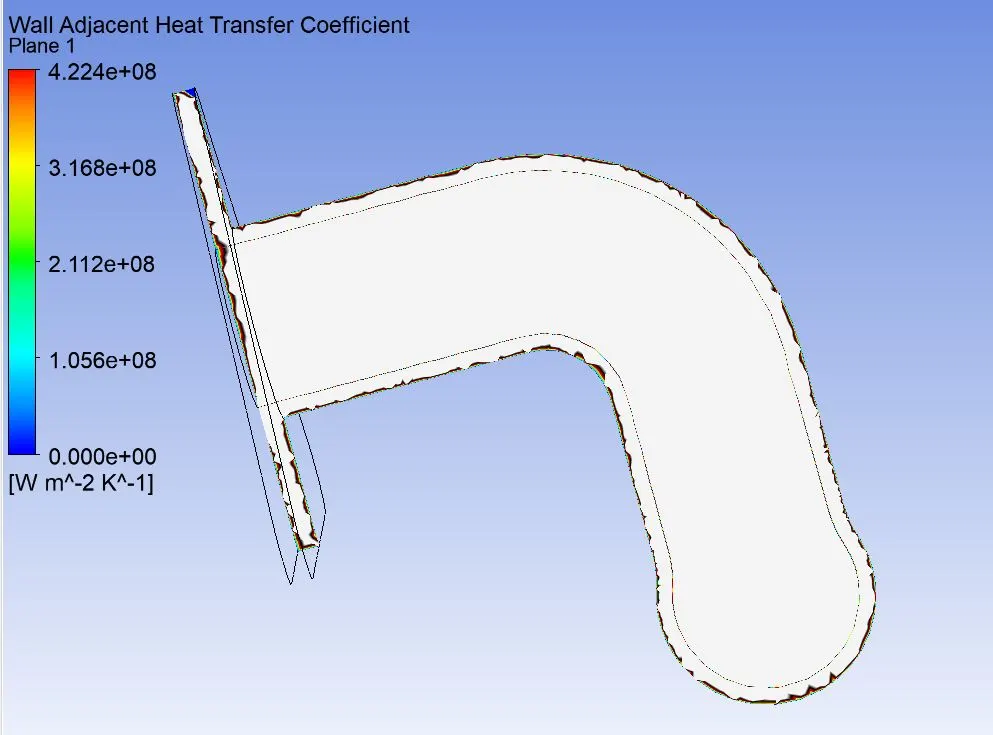
11. Insert - Plane, Create an xy plane and color mode - variable, variable - wall adjacent heat transfer coefficient.
12. Interpret the results and make a report.
Case 1 :
Case 2 :
Case 3:
Conclusion :
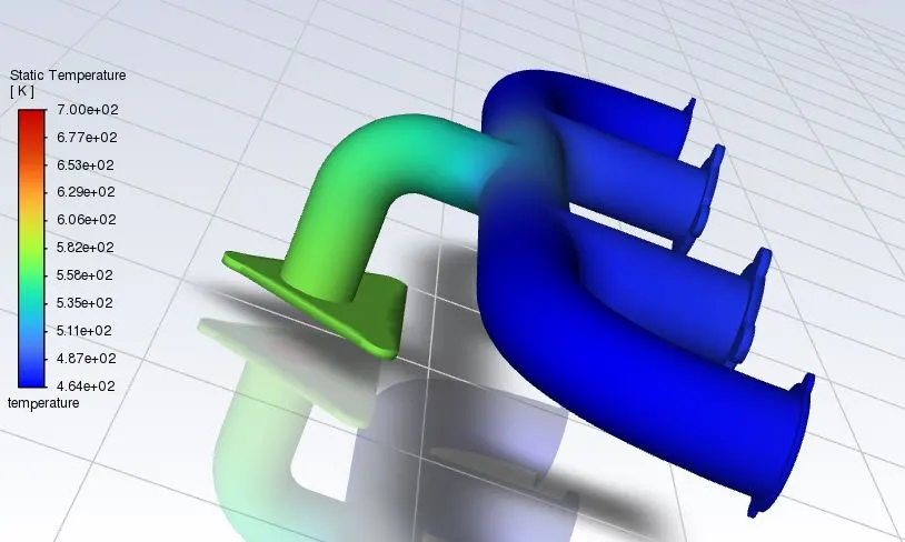
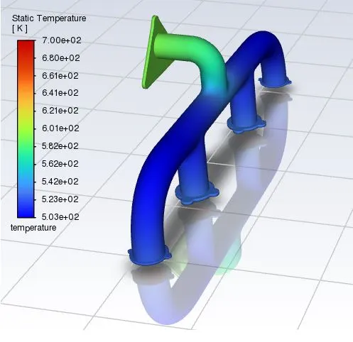
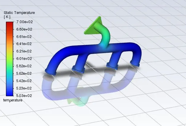
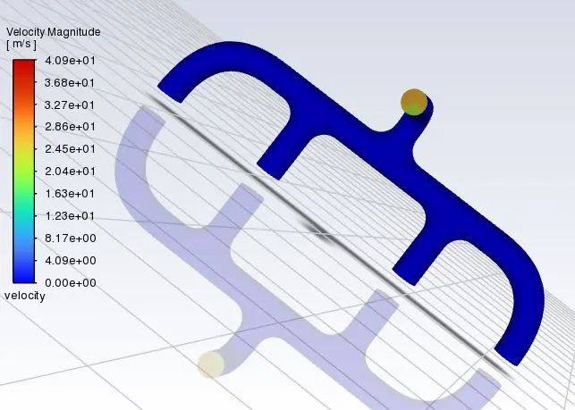
1. The temperature remains almost same until it reaches the throat region of outlet and it hikes rapidly since the velocity is increased at that region.
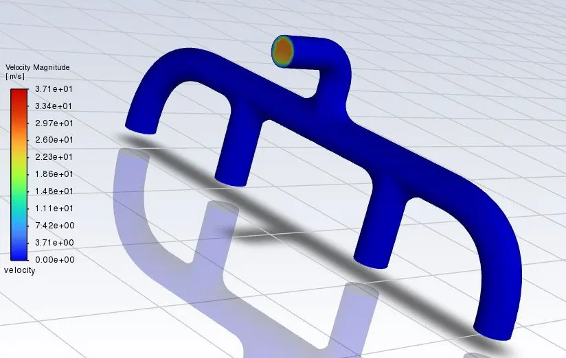
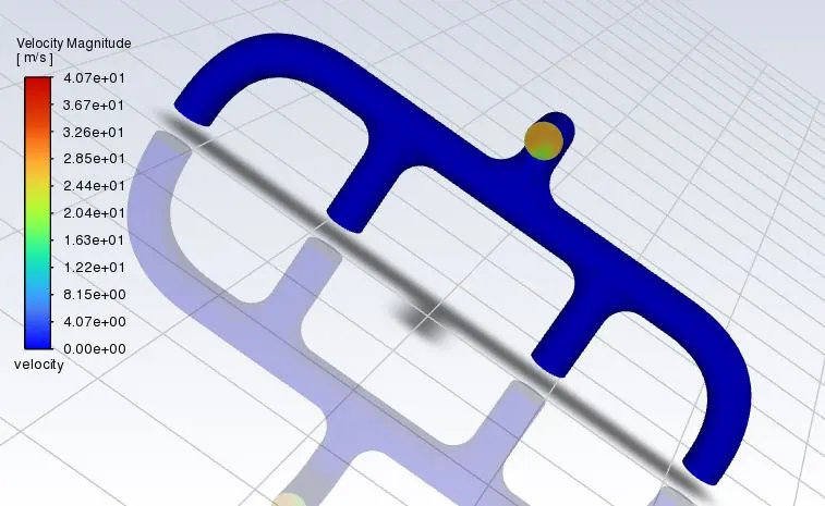
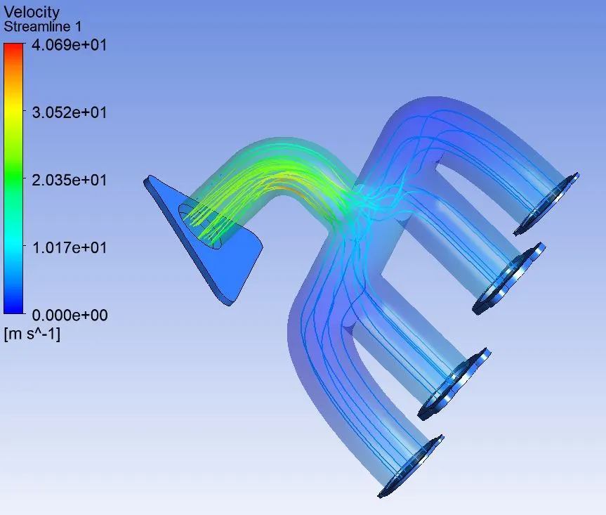
2. Velocity increases once the fluid comes closer to the throat region it is due to mass conversation ie where the fluid of all four inlet comes to a single outlet which eventually increases the velocity with turbulence mixture of fluids.
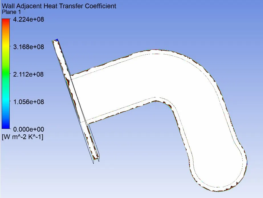
3. As we go with finer mesh, we can see the temperature, velocity & wall heat transfer coefficient increases . The case 3 mesh is more finer and it has highest velocity of 40.9m/s.
4. The maximum temperature is also produced at the curvature of the throat where the maximum heat transfer occurs due to conduction. Therefore, the Wall adjacent heat transfer Coefficient is higher at that location.
5. Finer mesh gives more accurate results.
6. Methods for Verification of HTC Predictions:
- Compare with experimental data
- Grid dependency test
- Comparison with analytical solution.
- Mesh Quality
- Fluid property representation
- Choosing the type of flow. ie laminar or turbulence.