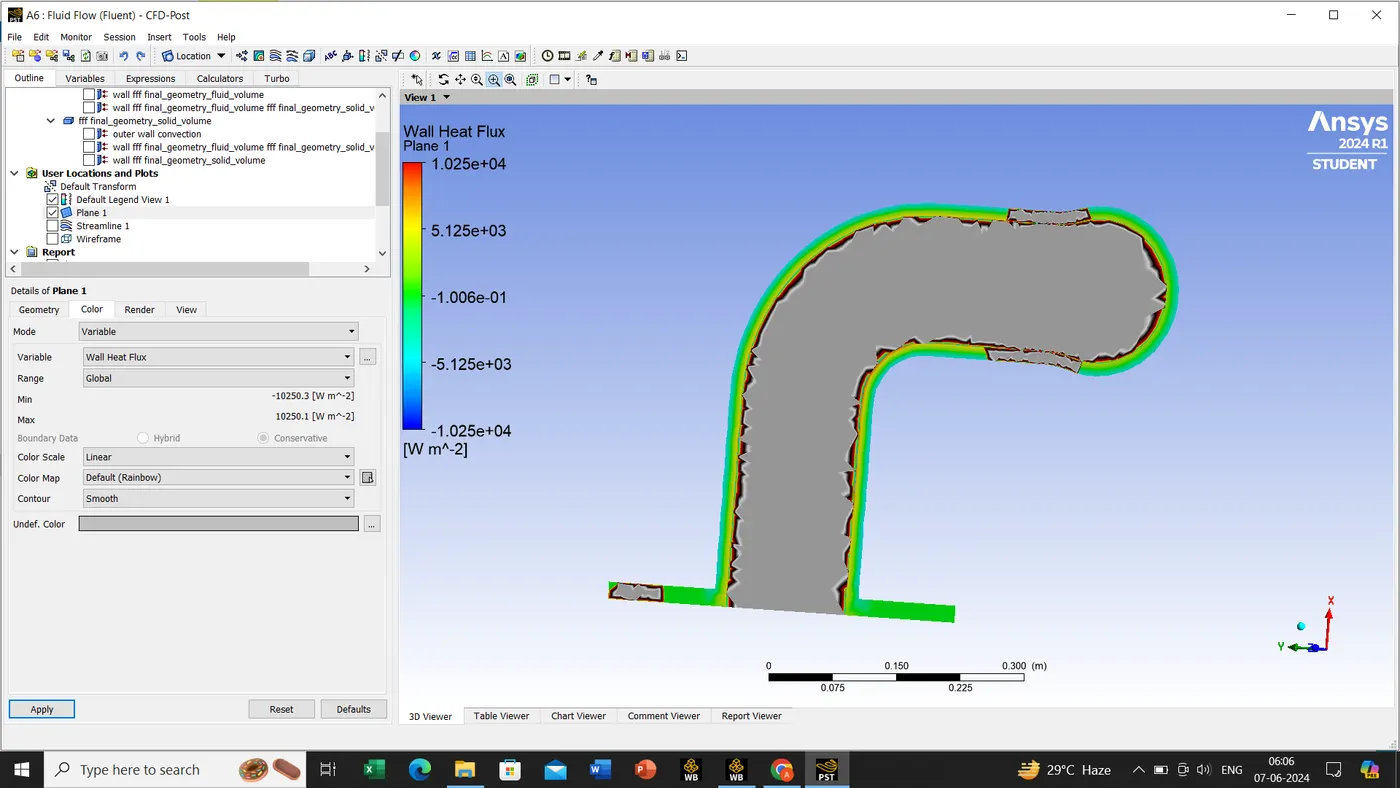
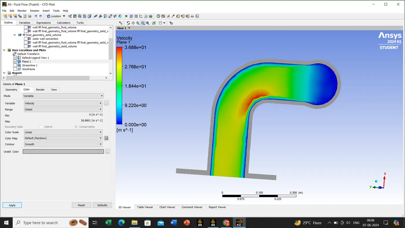
Week 4 - CHT Analysis on Exhaust port
Aim:-
The objective of the report is to perform a conjugate heat transfer(CHT) analysis on the exhaust port and validate the results. The CHT analysis is done in which conduction and convection of heat transfer takes place and simulation is performed by using turbulence model in ansys fluent.
Theory:-
The exhaust manifold is a vital component in internal combustion (I.C.) engines, significantly influencing their performance. It acts as the pathway for hot exhaust gases and sound waves produced during the combustion process to be expelled from the engine. Positioned between the engine cylinder head and the exhaust pipe, the manifold experiences extreme temperature and pressure conditions, particularly during and after the exhaust stroke.
Function and Importance
Collection of Exhaust Gases: The exhaust manifold is connected to the engine cylinder head, featuring multiple ports that correspond to each engine cylinder. It gathers exhaust gases from each cylinder and directs them into a single exhaust pipe.
Temperature and Pressure Resistance: The manifold must endure rapid and extreme temperature changes, as the exhaust gases are extremely hot. This thermal stress requires materials capable of withstanding high temperatures without deteriorating.
Material Selection
- Gray Cast Iron: This material is typically used for exhaust manifolds because of its excellent heat resistance, durability, and relatively low cost. Gray cast iron can handle the high temperatures and thermal cycling common in exhaust systems, minimizing the risk of warping or cracking.
CHT (Conjugate Heat Transfer) analysis is used to study the interaction between fluid flow and solid structures in terms of heat exchange. This type of analysis is crucial in various engineering applications where thermal performance and heat management are critical.
Why CHT Analysis is Used
Thermal Management: In systems where both fluids and solids are involved, such as electronics cooling or engine components, understanding heat transfer is essential to prevent overheating and ensure efficient operation.
Design Optimization: CHT analysis helps in optimizing designs for better thermal performance, energy efficiency, and material selection. For intance, in heat exchangers or HVAC systems, it can identify areas where heat transfer can be improved.
Safety and Reliability: Accurate heat transfer predictions are vital for ensuring the safety and reliability of equipment and structures, particularly in aerospace, automotive, and power generation industries where temperature extremes can affect material properties and performance.
Performance Prediction: In applications like gas turbines, nuclear reactors, or chemical reactors, CHT analysis helps predict how components will perform under various thermal conditions, aiding in design and operational decisions.
Where CHT Analysis is Used
Aerospace Engineering: In the design of turbine blades, rocket engines, and heat shields, where the interaction between high-speed gases and solid surfaces must be understood.
Automotive Engineering: In the cooling systems of internal combustion engines, electric vehicle batteries, and brake systems to ensure efficient heat dissipation.
Electronics Cooling: For designing cooling solutions in high-performance electronics, including CPUs, GPUs, and power electronics, where managing heat is crucial for performance and longevity.
Power Generation: In nuclear reactors, gas turbines, and other power generation systems where efficient heat transfer affects overall efficiency and safety.
HVAC Systems: In heating, ventilation, and air conditioning systems to design efficient heat exchangers and improve overall system efficiency.
Chemical and Process Engineering: In reactors, distillation columns, and other process equipment where heat transfer between fluids and solid walls is critical for process control and efficiency.
Biomedical Engineering: For designing devices like thermal ablation tools or implants where heat transfer between biological tissues and devices needs to be controlled.
Key Techniques in CHT Analysis
Computational Fluid Dynamics (CFD): Used to simulate the fluid flow and heat transfer processes. CFD tools can model complex geometries and flow conditions to predict thermal performance.
Finite Element Analysis (FEA): Used to analyze the solid structures for thermal stresses and deformations caused by heat transfer. FEA tools can handle complex material properties and thermal loads.
Coupled Simulations: Combining CFD and FEA for a comprehensive CHT analysis. This involves simultaneous solution of fluid flow and solid heat conduction equations to accurately capture the interaction between fluids and solids.
Conclusion
CHT analysis is a critical tool in many engineering fields where heat transfer between fluids and solids significantly impacts performance, efficiency, safety, and reliability. By using advanced simulation techniques like CFD and FEA, engineers can design and optimize systems to better manage heat, ensuring optimal performance and longevity.
Procedure:-
Firstly we shall open the workbench or ansys software.
Step 1:- Geometry
Once the geometry/spaceclaim tab is open we will insert the model by drag and drop, for these operation we will using the units in Meters.
File->Spaceclaim options->Units.
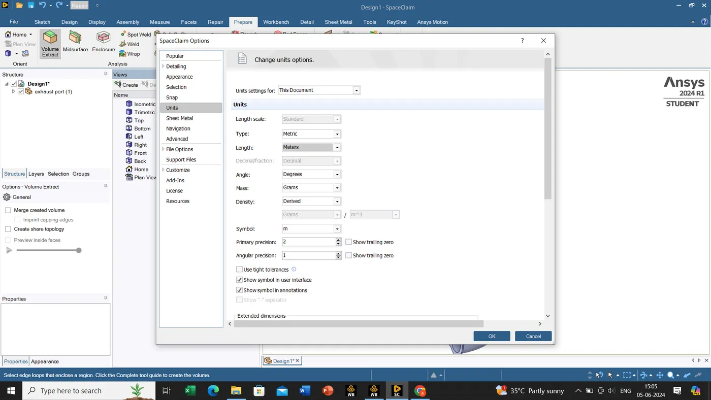
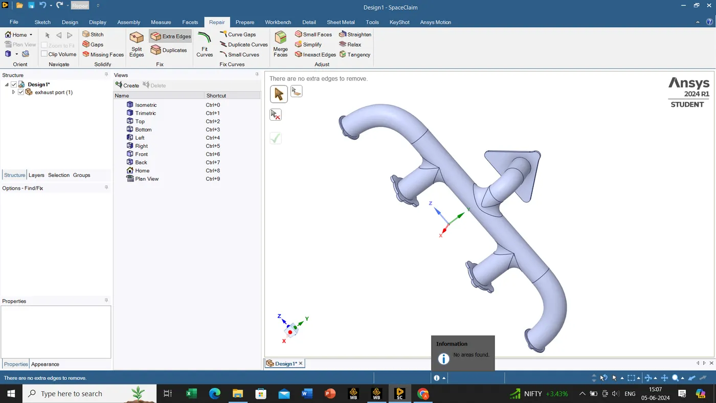
For extra edges or duplication present in the model can be repair with the help of repair tool.
Repair-> extra edges or duplication or etc., -> select the whole model, If something suspicions will be there in model it will be indicate in the red color or the green color tick mark will be visible by clicking the arrow all the extra edges or duplication or etc., will be removed.
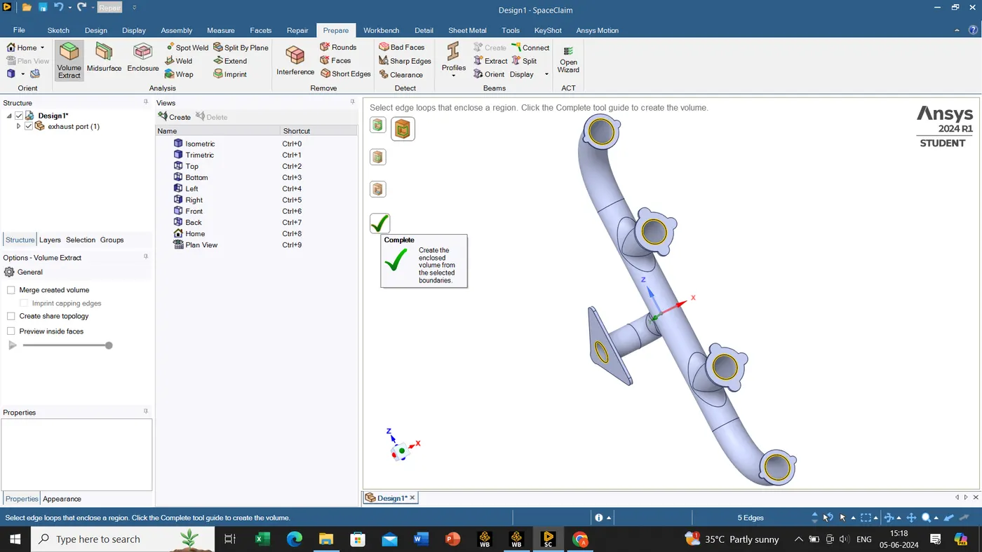
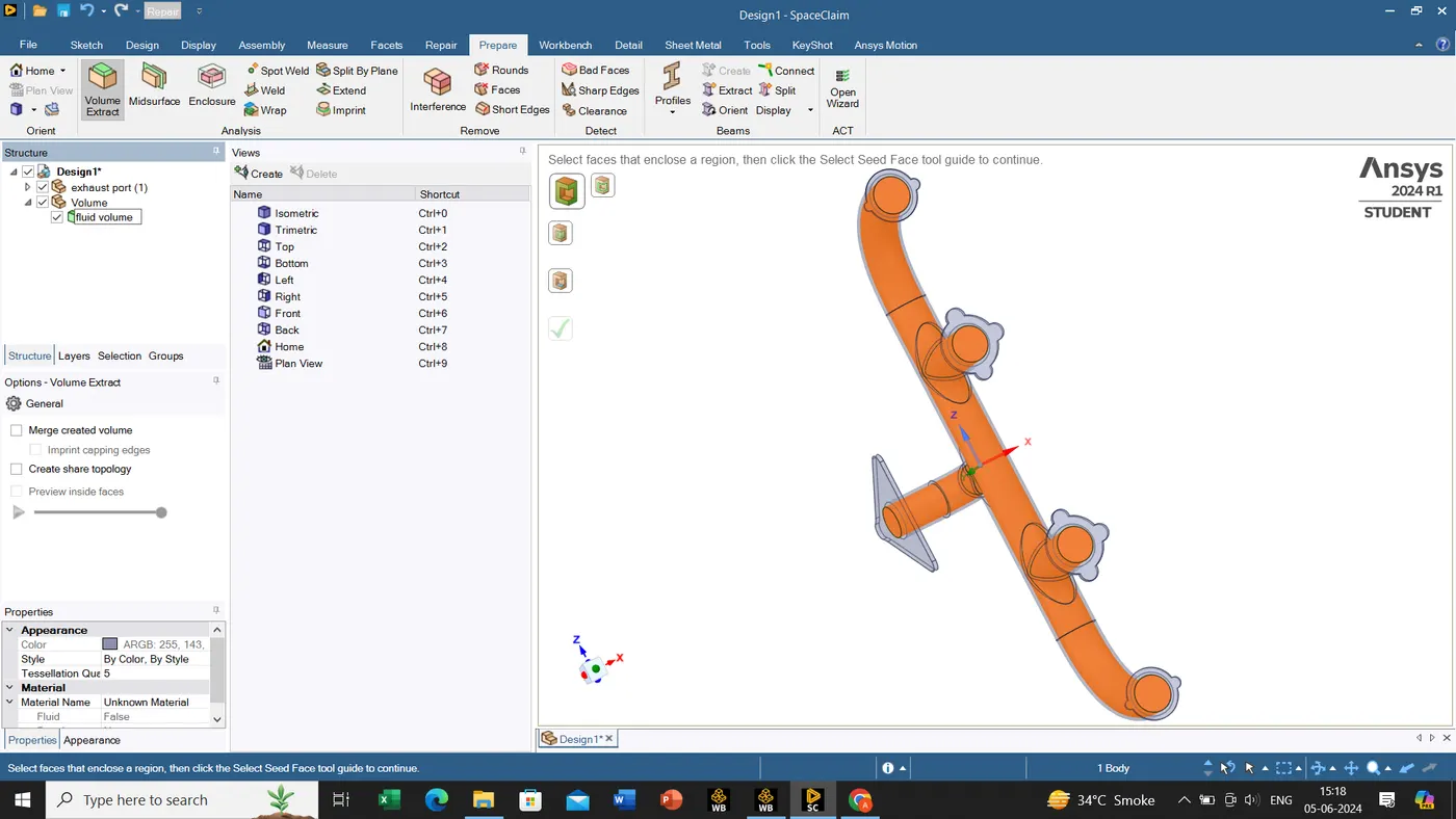
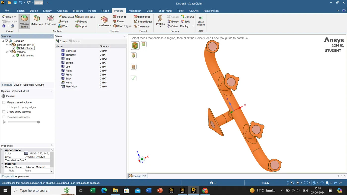
Prepare-> volume extract-> select the edges -> Click on the green tick mark to be applied.
showing below some images related to volume.
Step 2:- Meshing
Now we are opening the meshing tab.
before generating the mesh we will assign the names.
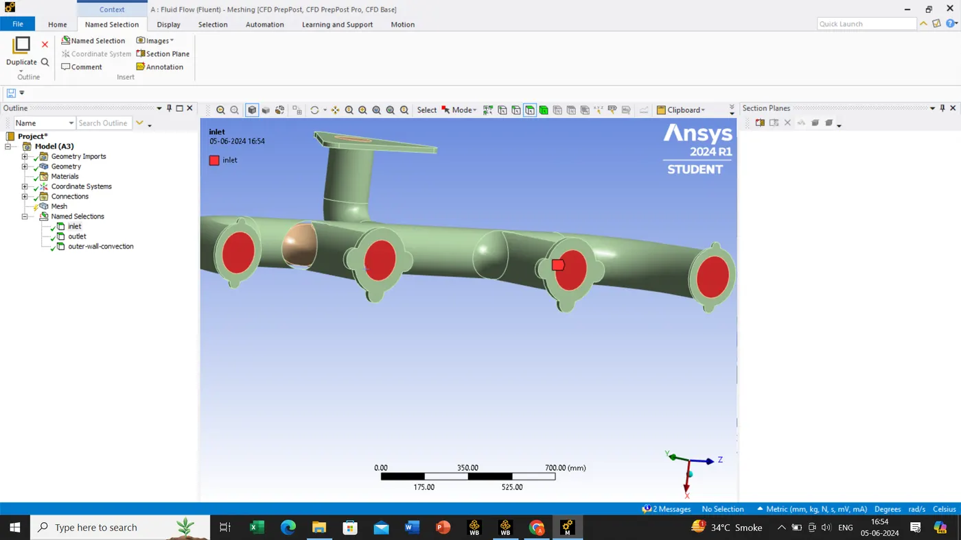
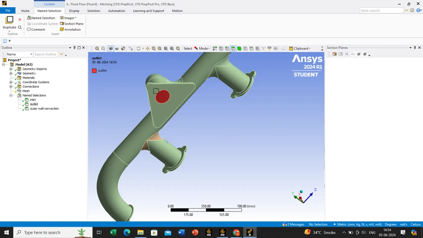
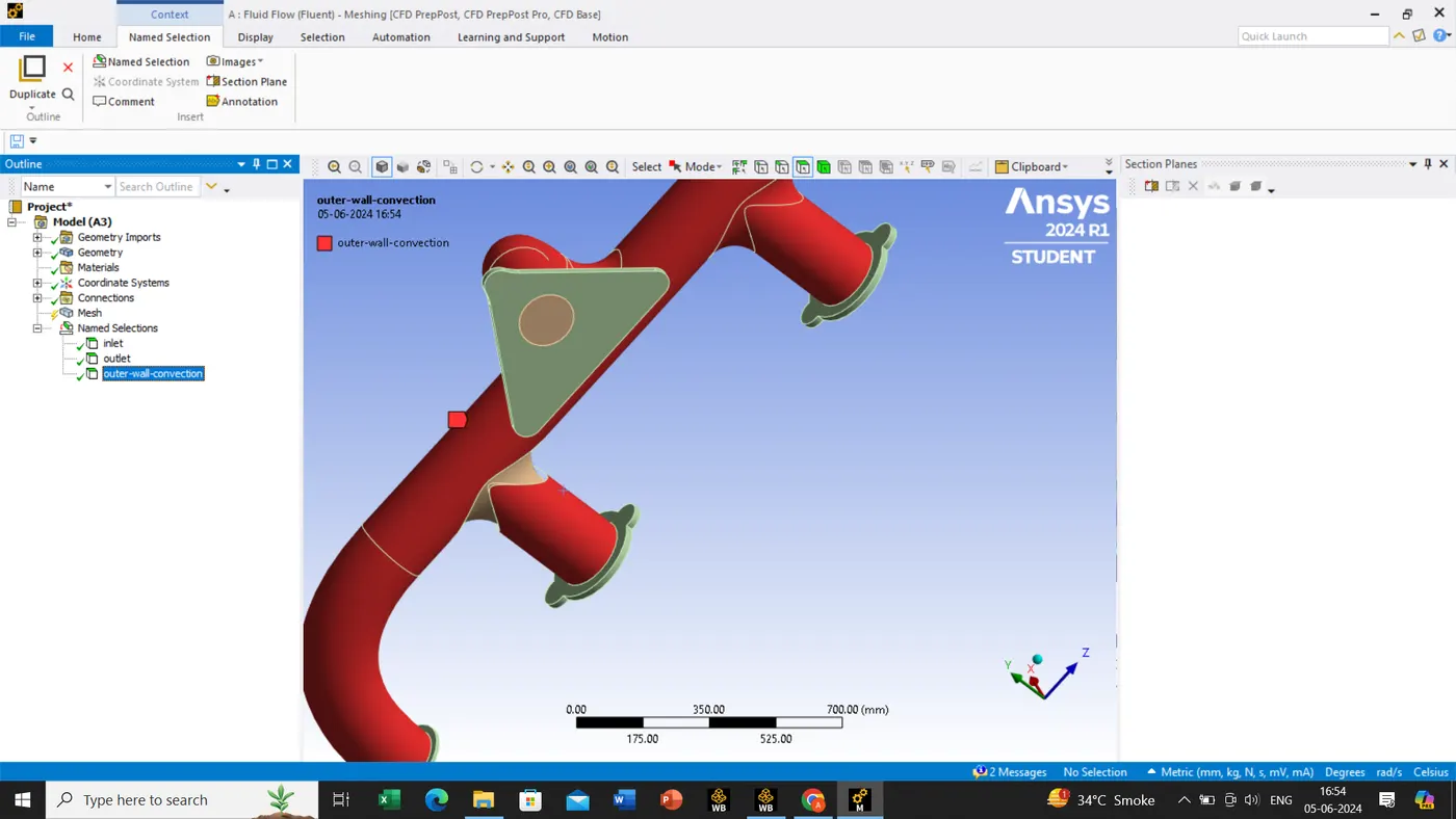
Mesh->generate the mesh
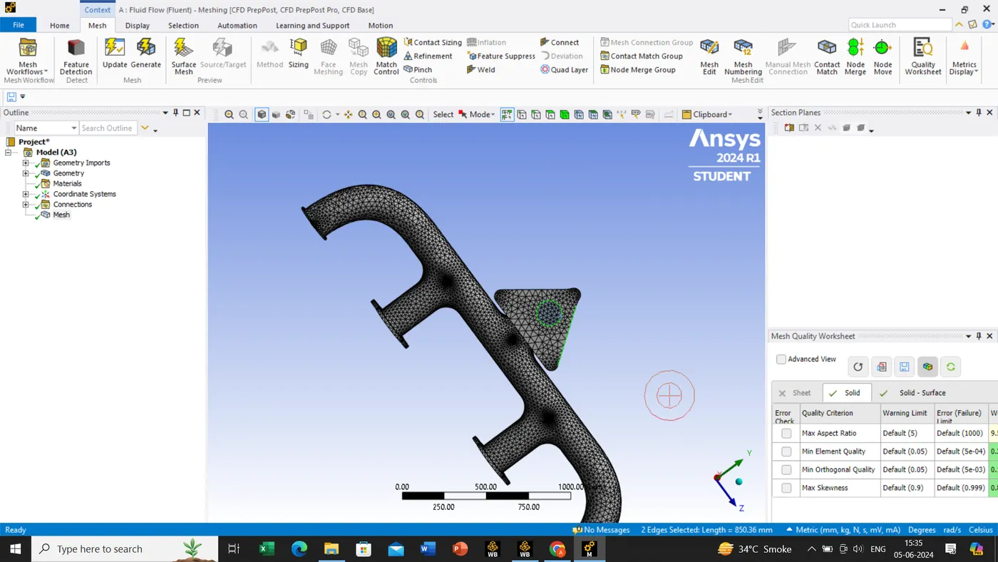
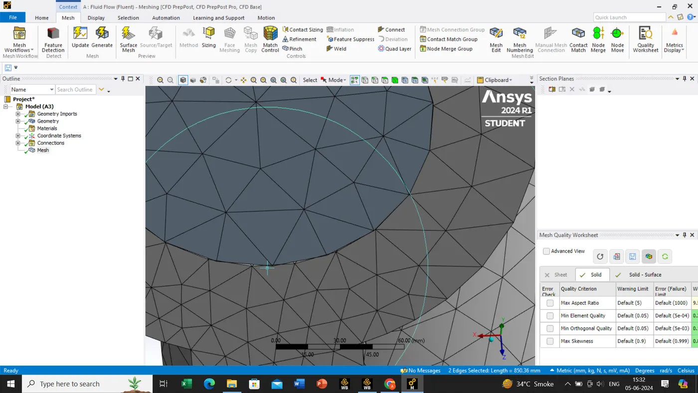
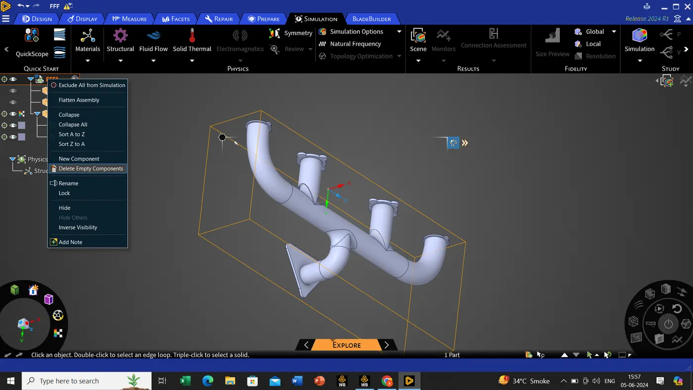
As we can see there is a gap in between the meshing we have to repair it since during the CHT simulation we will be facing problems due to overlap surface.so we required the meshing shall be done properly to repair this surface we will go back to geometry and enable the share topology but before enabling the share topology we have click on the solid volume and fluid volume with the help of ctrl button, right click and create the new component with the name of final geometry. click on the FFF and right click select the empty components so that it will be deleted.
To enable the share topology->FFF design->click->share topology
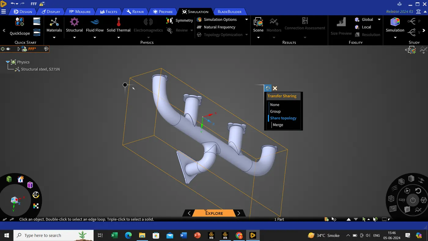
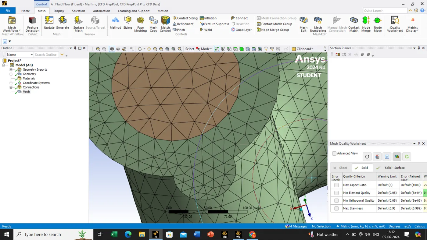
we will be regenerating the mesh, as we can see the mesh is proper there is no gap and the vertices are properly alligned as shown below.
Step 3:- ANSYS
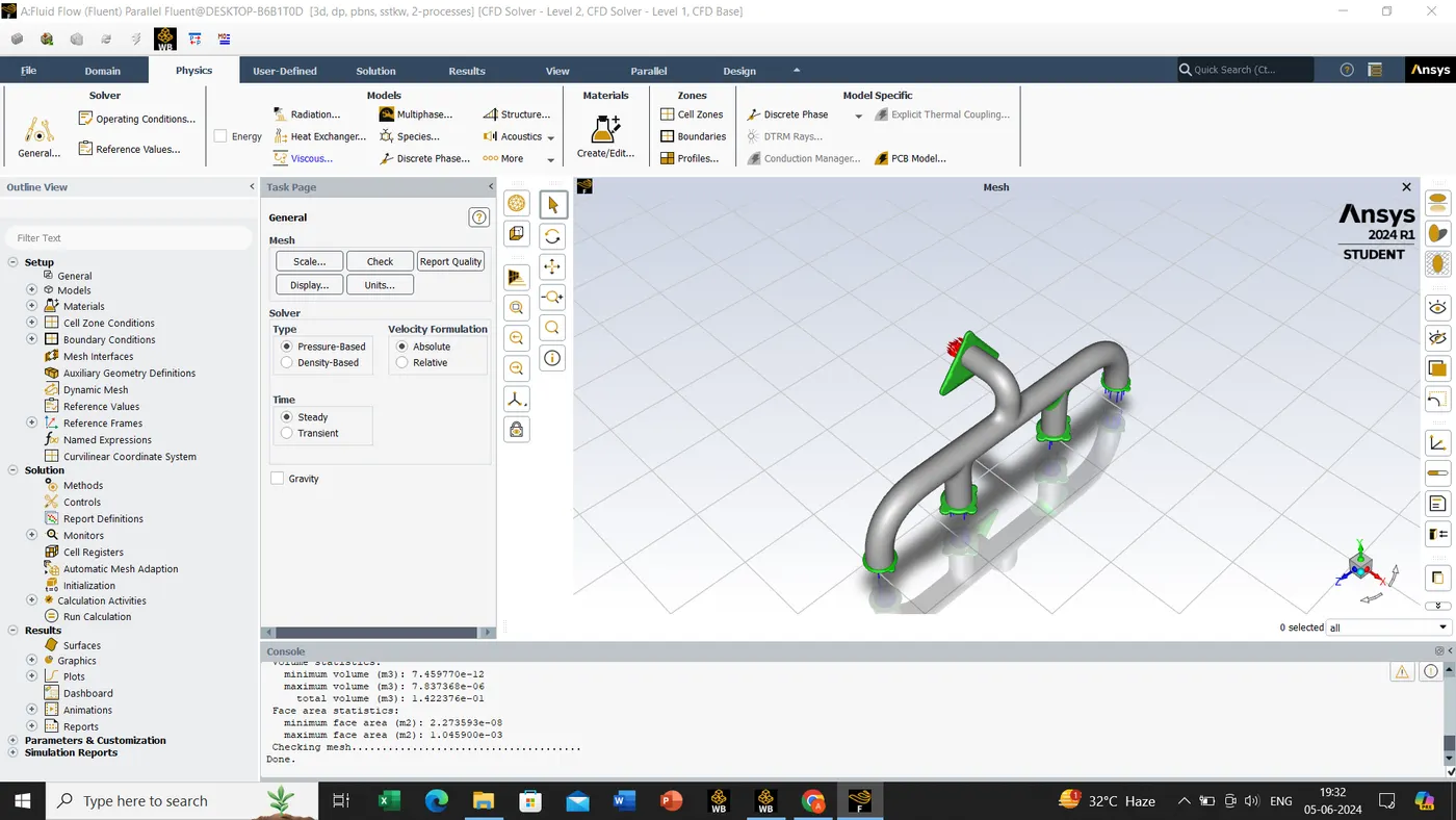
After meshing we will be opening the ANSYS fluent. once the tab is open we will be waiting for a couple of minutes to load the model.
for this simulation we will be using,
type->pressure based
Velocity formulation->Absolute
Time->steady
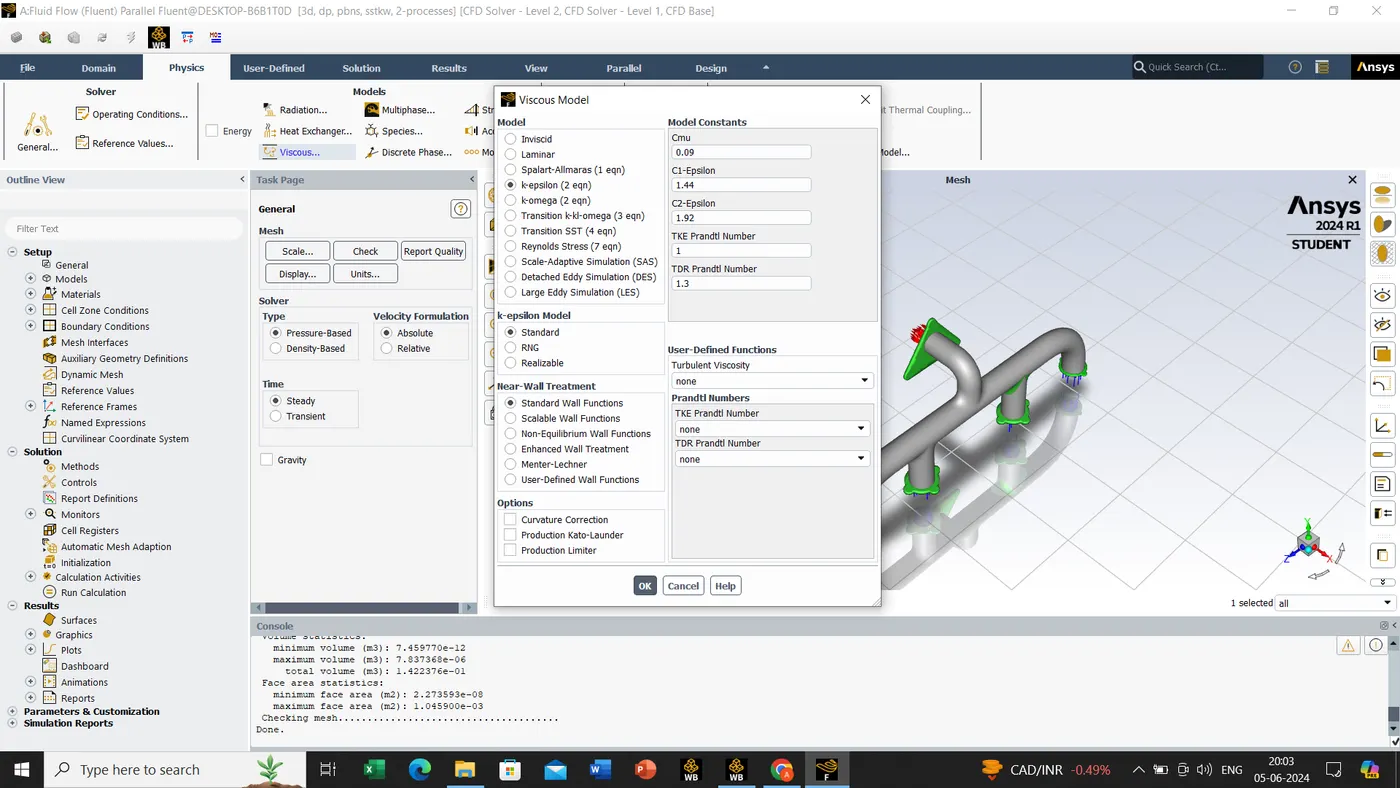
Physics->viscous->viscous model(select the K-epsilon)
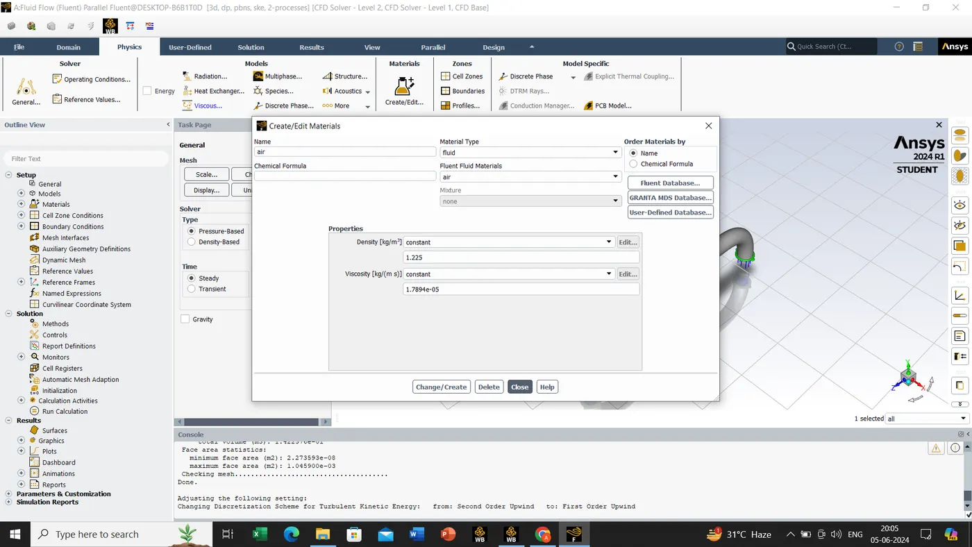
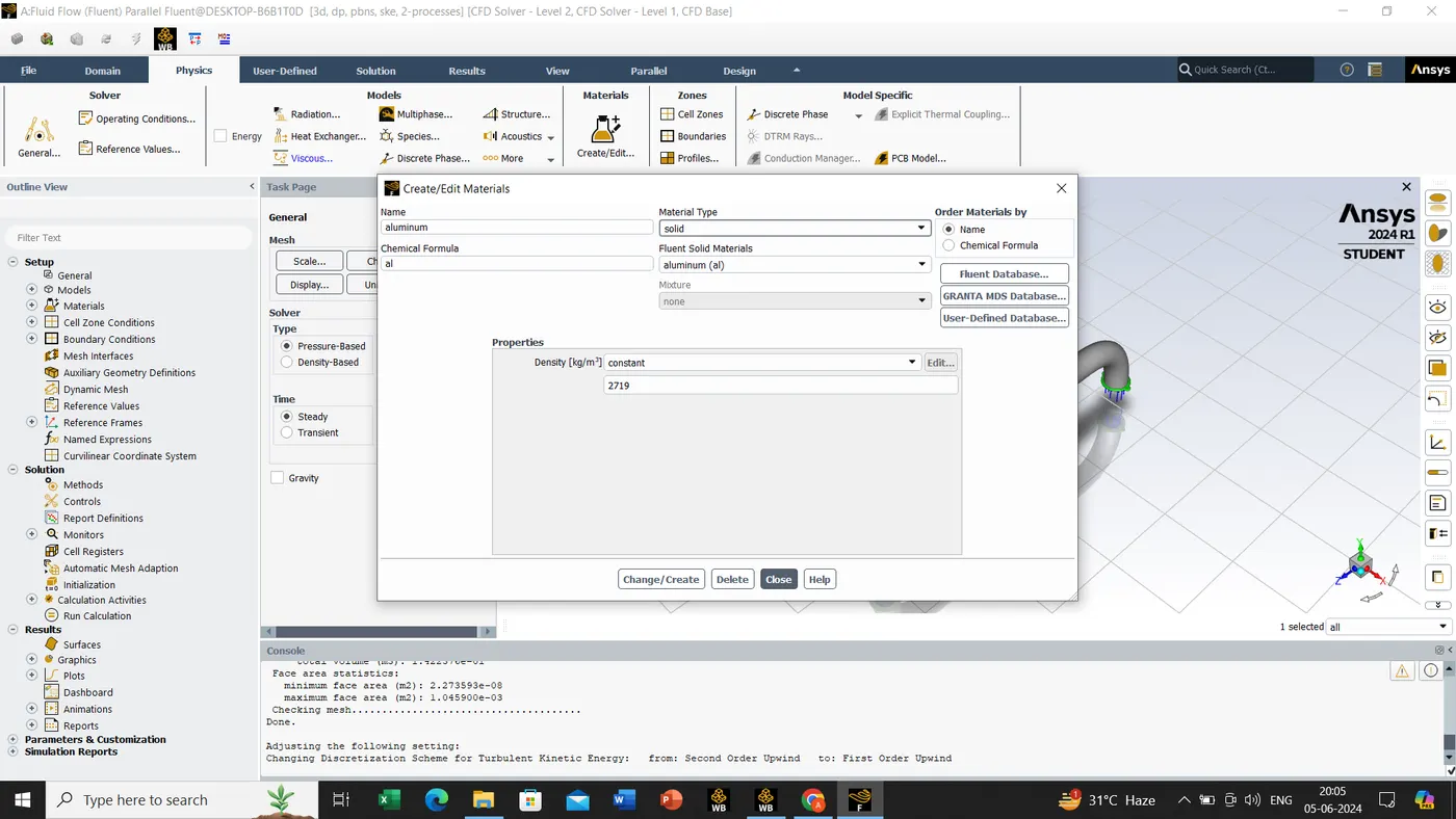
For material we will be using the default material air and for aluminum we will be using solid.
Physics->material
Physics->boundary conditions.
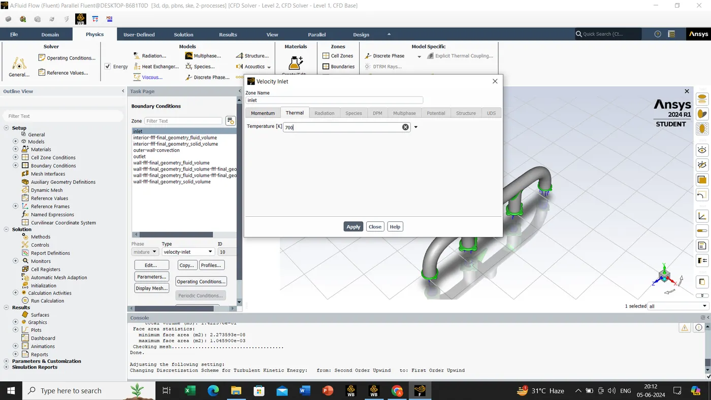
for inlet the BC for velocity is 5m/s and Temperature is 700K
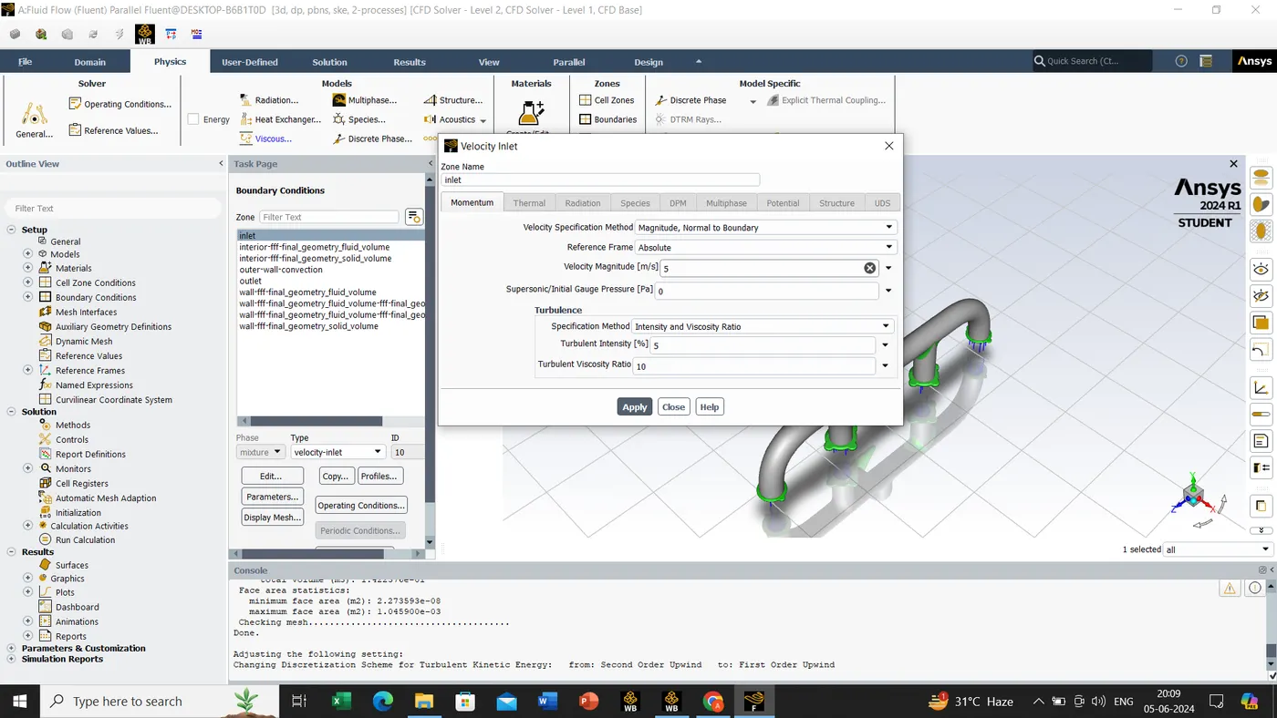
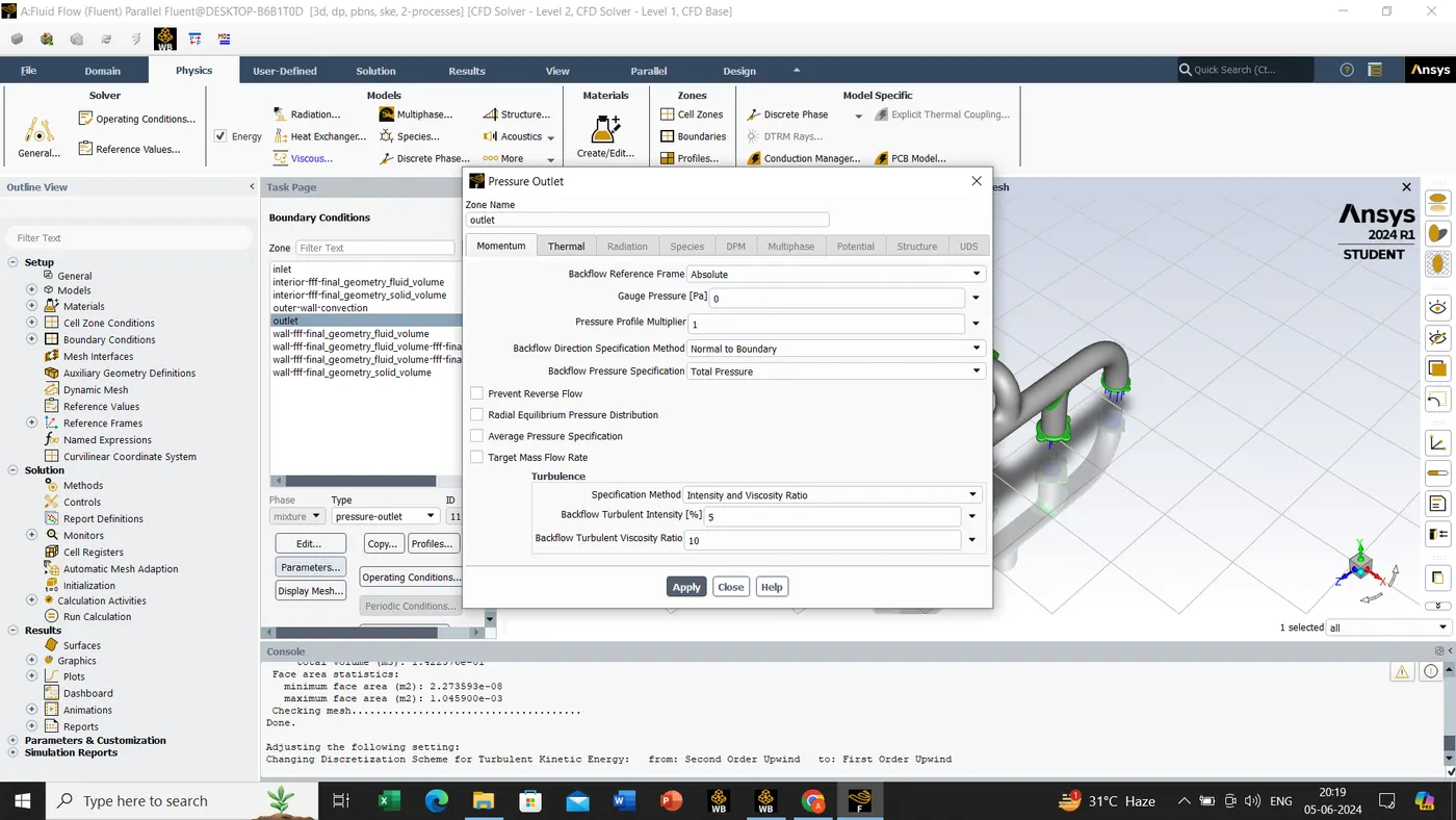
for outlet the BC will be default
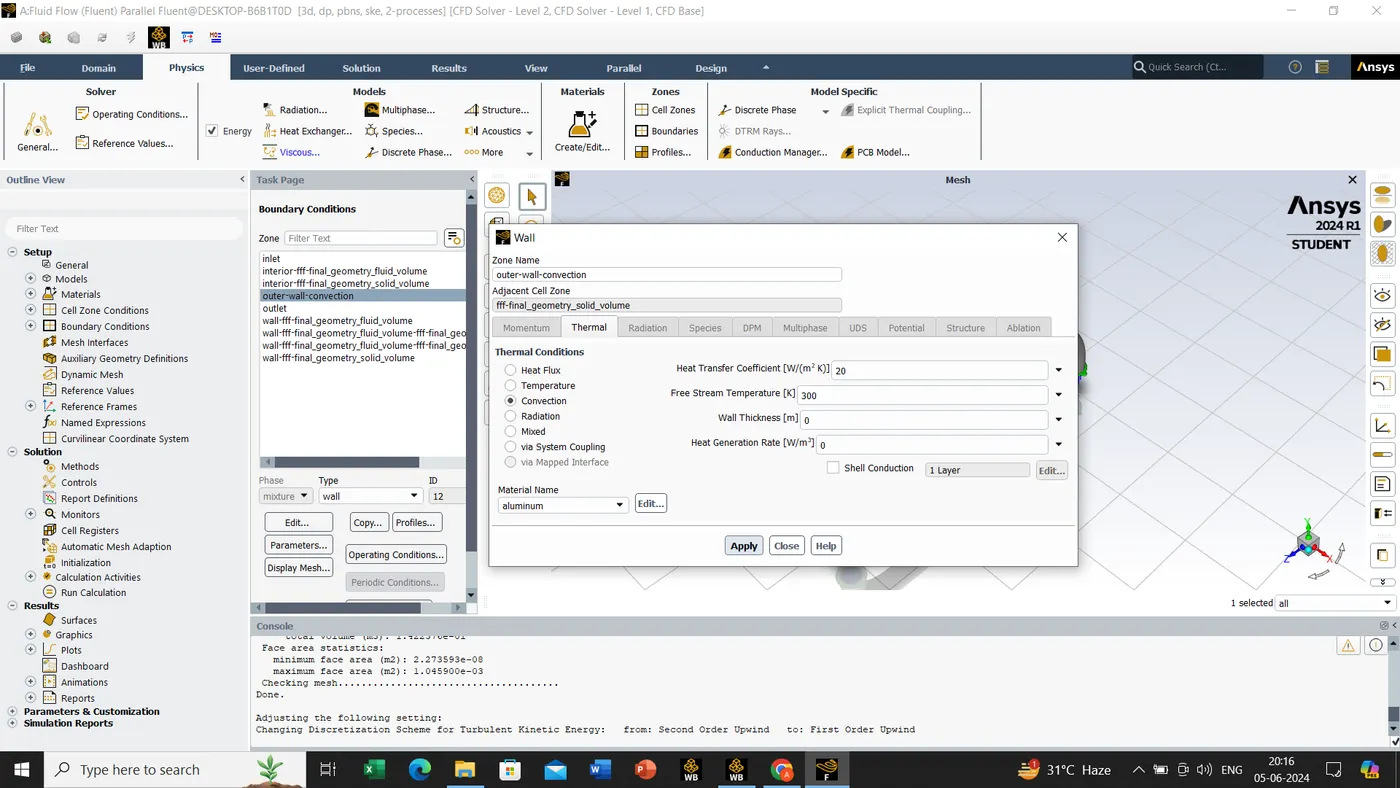
for outer-wall-convection ->convection->HT=20 and temp=300
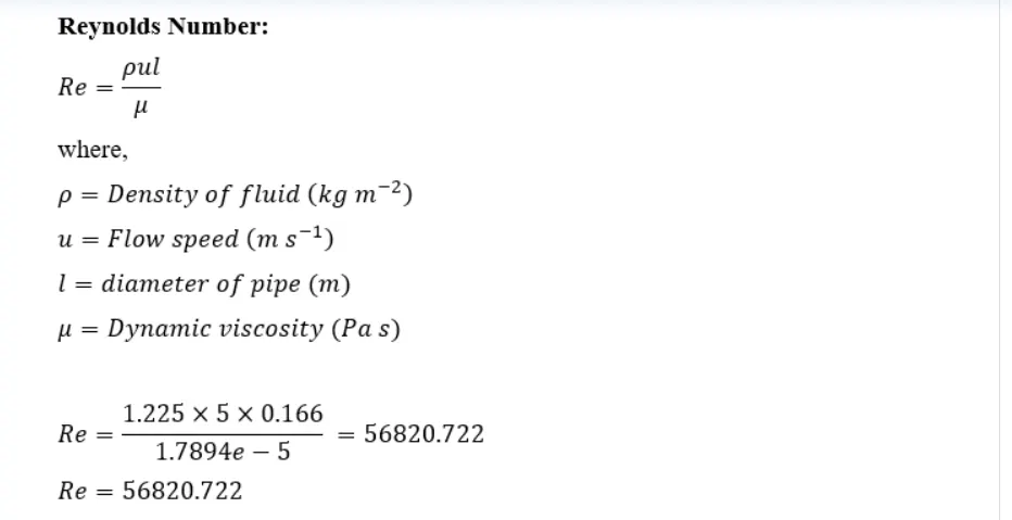
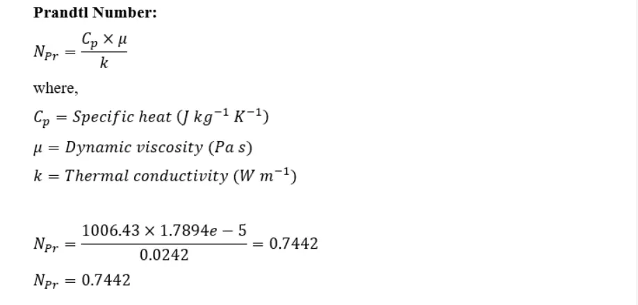
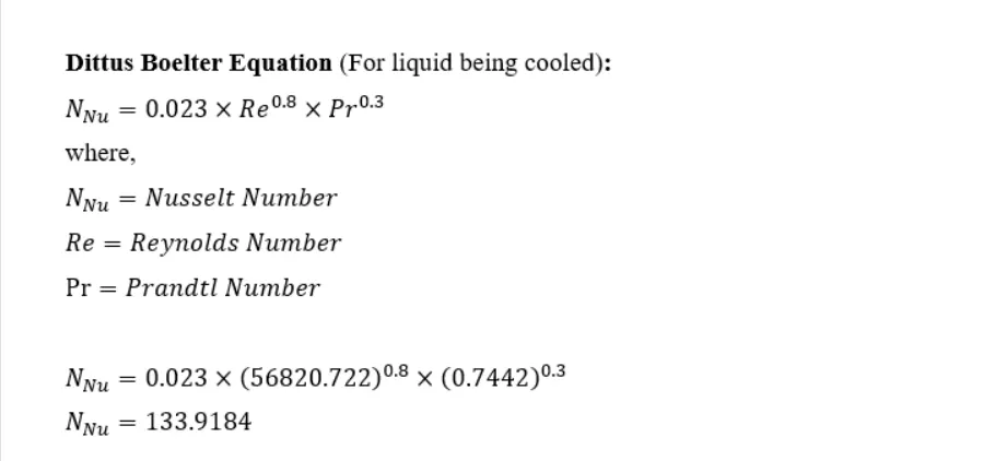
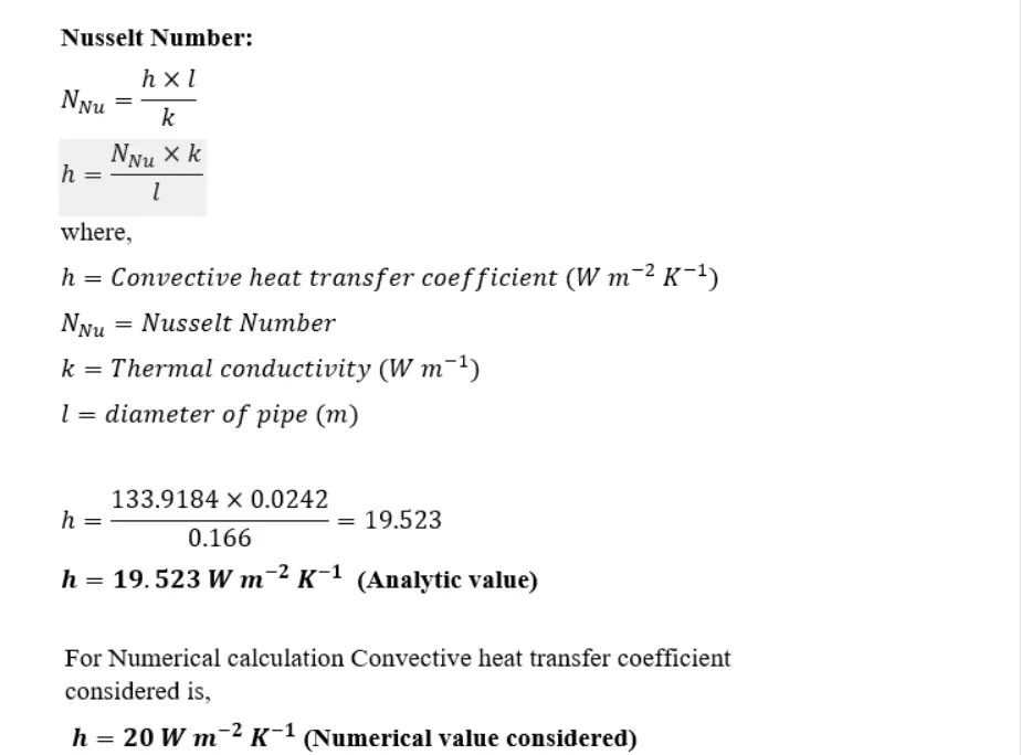
solution->method
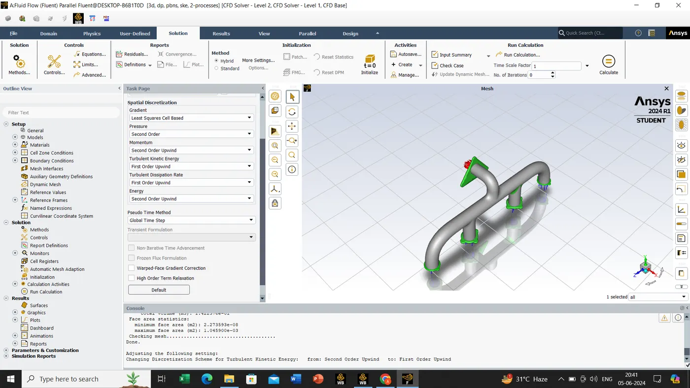
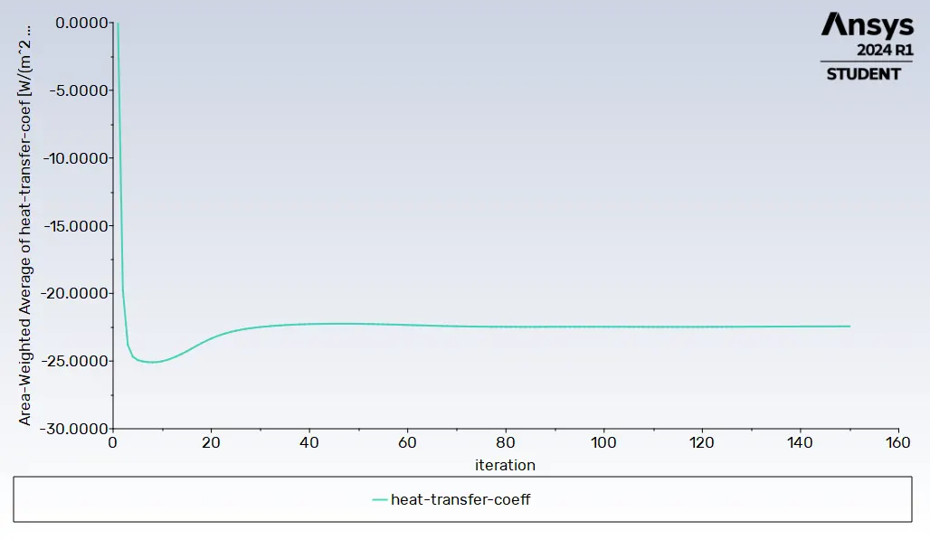
solution->definitions->new->surface report->area weighted average
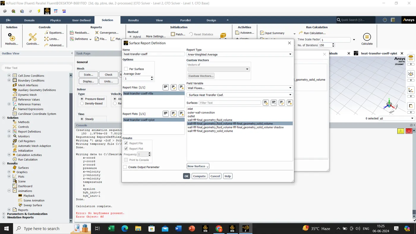
Initialize the model by using hybrid method.
Simulation is carried out for a total of 150 iteraations
Plots & contour :-
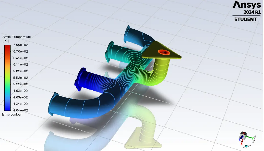
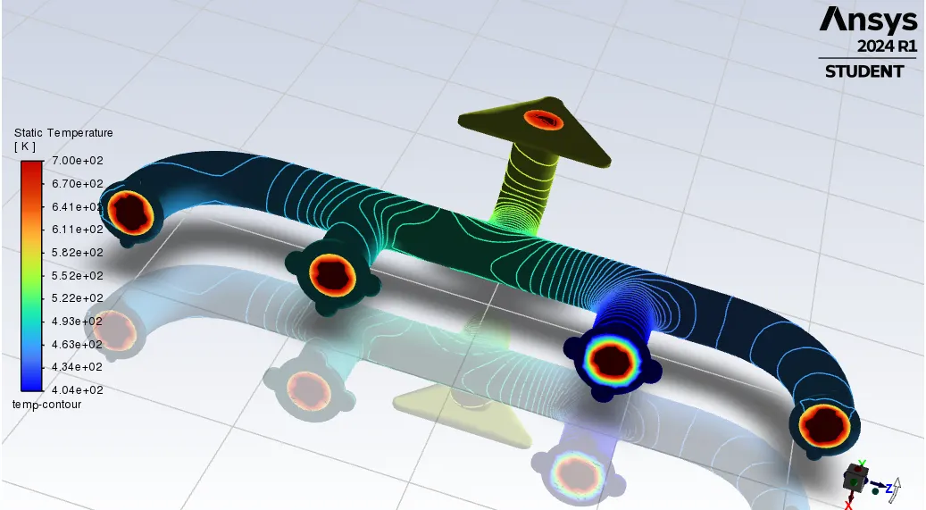
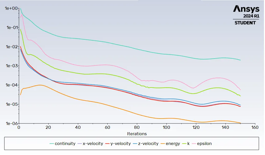
Step 4:- Result
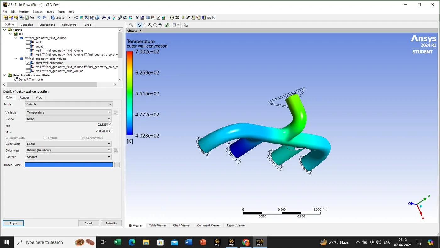
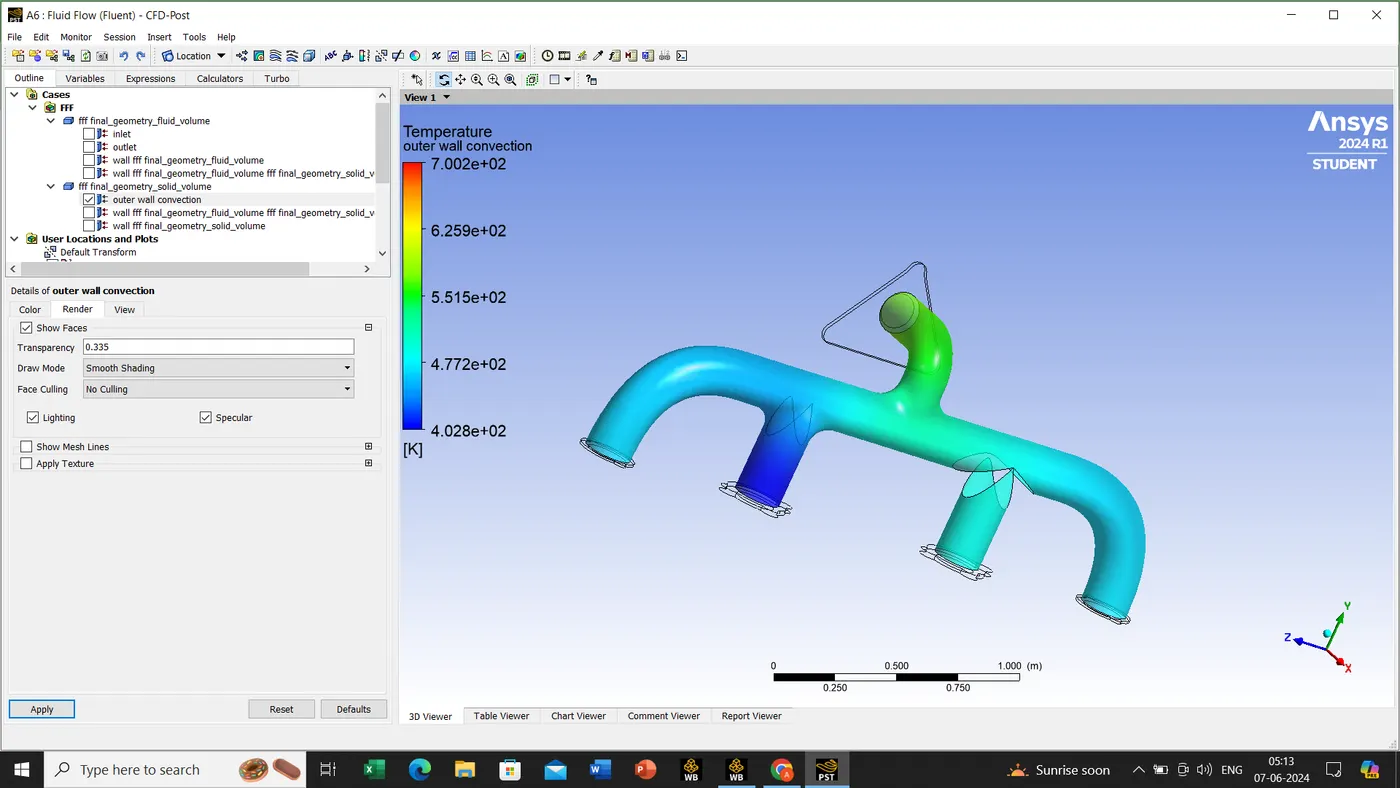
we will select the fff final_geometry_solid_volume->tick the outer wall convection->double click on outer wall convection->color->select the mode in variable->In variable select the variable in temperature->click on apply->Render->transparency should be 0.335 and click on apply button.
Click on the stream line ->starts from inlet->no of points 25->variable is velocity.
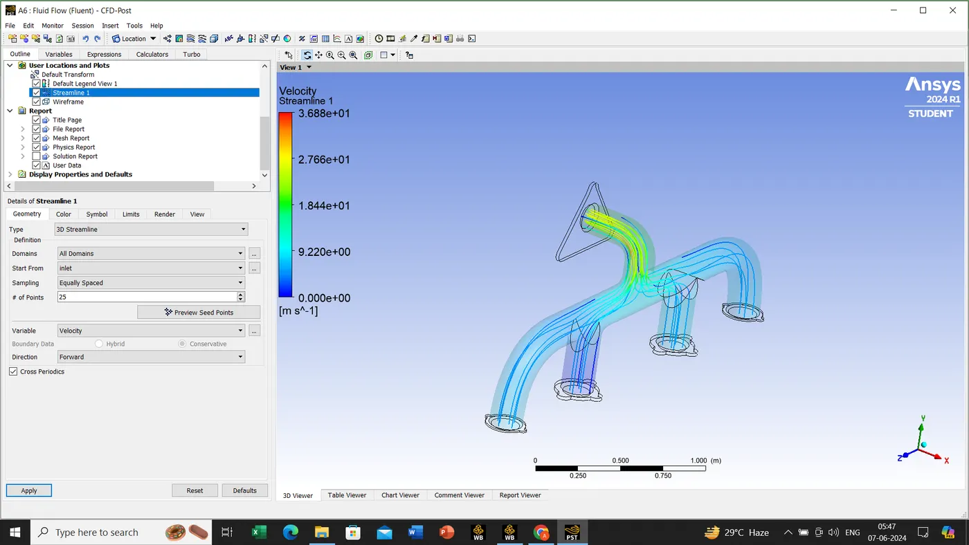
we can say that the velocity is less in exit as compare to inlet velocity.