Week 2 Challenge : Surface meshing on a Pressure valve
Aim:- Surface Meshing on a pressure vessel
Objective :-
For the given model, check for the geometrical errors and perform Topology clean up accordingly. Set three different target lengths as three different cases and mesh the model.
Intro:-
->ANSA- >Automatic net generation for structural analysis) is a computer-aided engineering tool for Finite Element Analysis and CFD Analysis widely used in the automotive industry. It is developed by BETA CAE Systems [Source: - Wikipedia]
->It is used for pre-processing task and it includes proper cleanup like a geometric clean up.
-> 2D & 3D it is very widely used in CA applications.
->ANSA maintains the association between CAD geometry and the FE mesh
Procedure:-
Step 1: - Importing the CAD Model
Go to the file - > open the file - > Search the location, where the CAD model is present- >Supposed another model is open in workspace then it will be discarded or saved - >Certain path where we had download or save the model, It can be identified by ‘’ ANSA’’ - >Select it & click on enter.
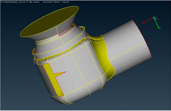
Step 2: - Geometry clean
Geometry checks _> Can we found above the workplace in the line of Script tool _> Checks _ > Geometry _ > Template _ > ANSA checks mode is on/off, click on it to ON
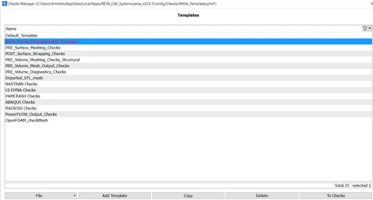
Click on To checks to reach at the start of geometry checks _ > Geometry should be visible and active _ > Select the types of checks i.e. single cons, double cons, overlap faces, triple faces and etc _ > Execute _ > Errors showed it should be solved.
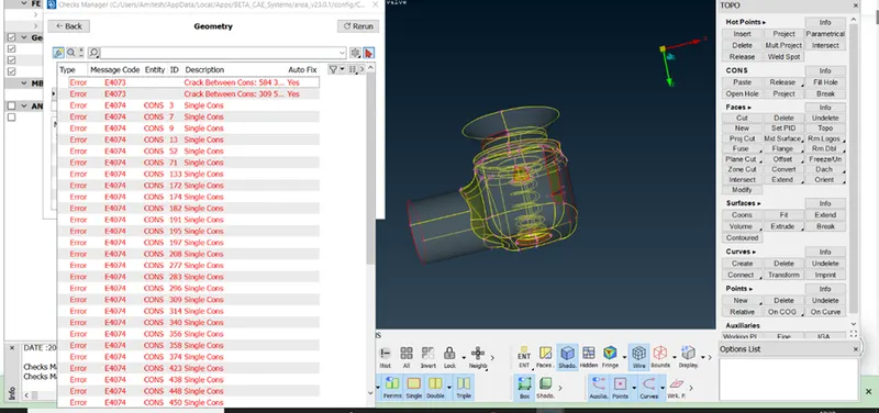
If we want to see the errors in the model like a preview then select the random errors in the geometry check and to select the whole model, we must drag down the cursor and select the model, later we had to click the mouse centre button then it will be shown in a current model where that exactly error is present with a white border.
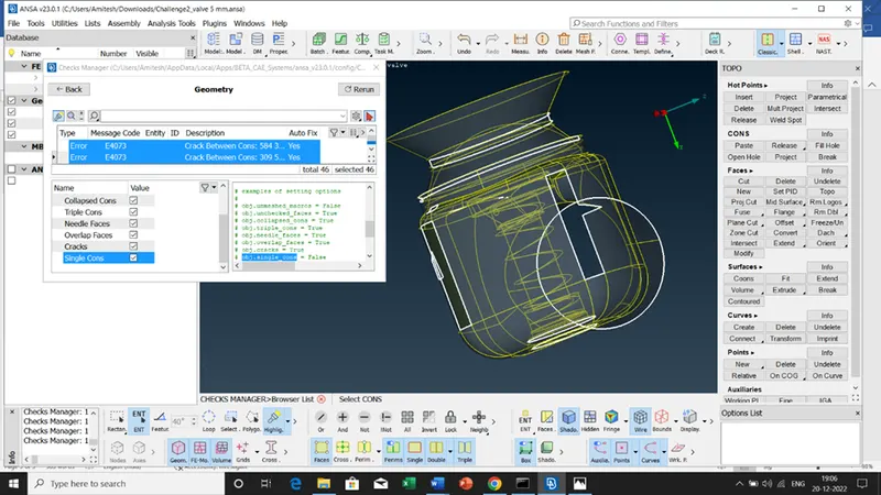
To see the single cons error, we had to deselect the double cons and triple cons along with the shadow tool so that we can only see the single cons error
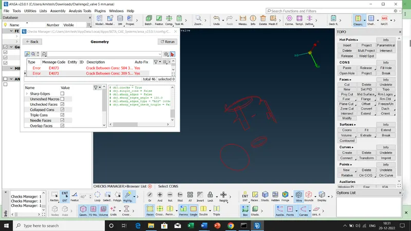
Objective of Geometry is to check the NO of errors present in the model.
Step 3: - Errors should be solved
Since the single cons error can be solved by using new faces
Click on Classic TOPO tool _ > Faces _ > New _ > Surface type _ > Select the Existing Surf _ > Select the Cons border through Cursor ì _ > Click the mouse centre button.
Existing surf surface type
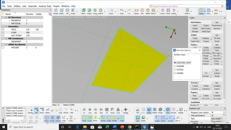
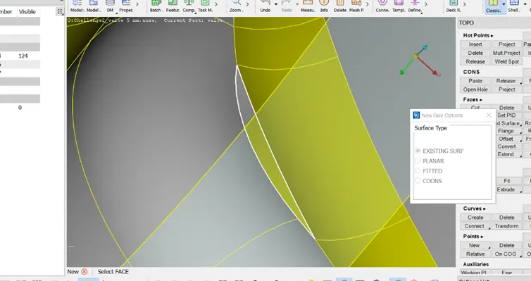
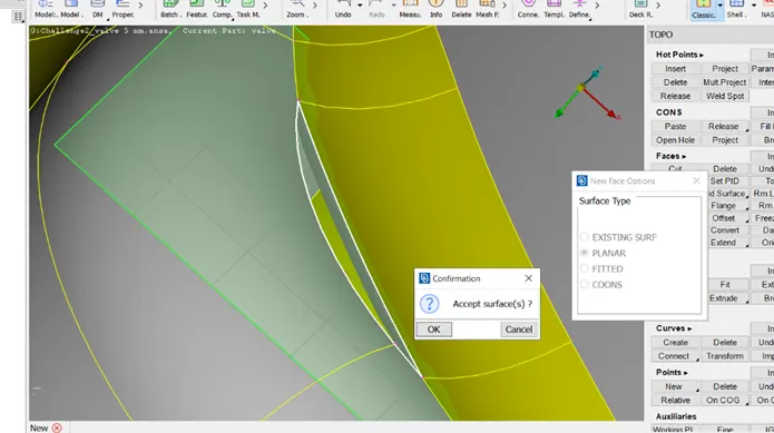
Note :- We can’t apply Existing Surf, Planar, Fitted, coons surface type in all the faces due to the improper surface face, for better understanding presenting some pictures below.
A] We can’t use existing surf surface tool due to improper face layer
B] We can’t use Planar surface tool due to improper face layer
C] We can’t use Fitted surface tool due to improper face layer.
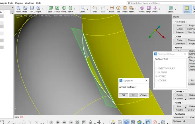
D] We can use Coon’s surface tool due to proper face layer.
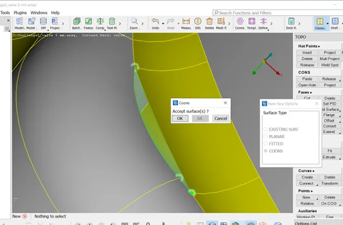
Similarly, we can use this tools for face layer.
Step 3:- PID
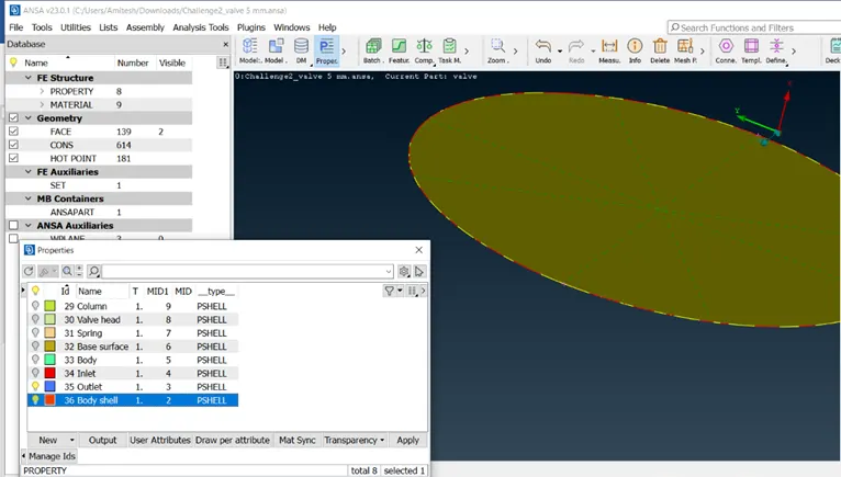
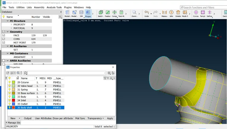
Properties _ > Click _ > New pop-up box, It will shows the Pshell contain or PID
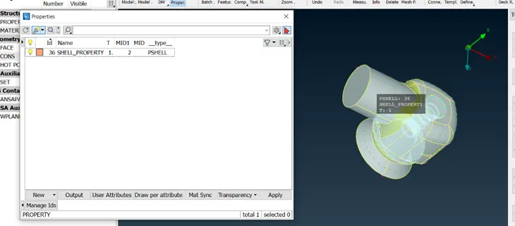
How to create a new PID?
To create a new PID_ > Right click _ > New _ > Pshell _ > new box will come up _ > Name (e.g.:- Outlet) _ > OK _> Properties new PID present _ > we can also change the colour by clicking twice on this □
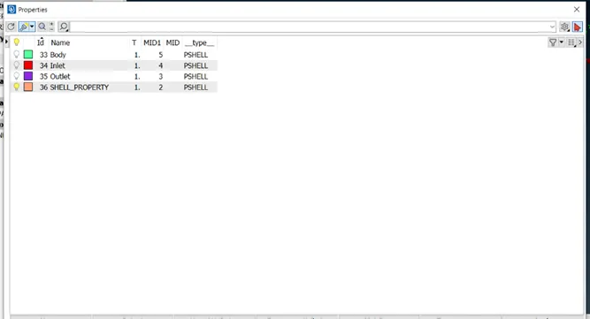
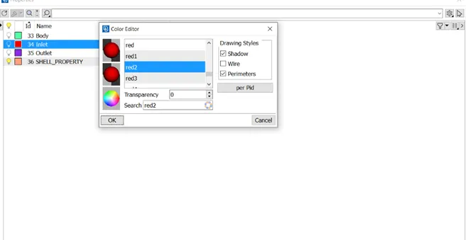
To assign PID _ > Click on the PID, which has to apply on our model _ > Right click _ > Apply _ > Go to the model _ > Take the cursor to the Cross edge / face and click centre button.
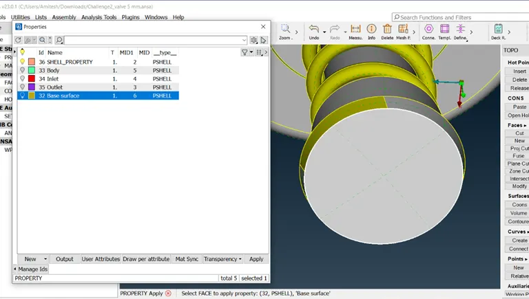
Note: - The moment when we are going to assign the PID for outer region we had to first eliminate the inner part since for this model we had a spring, Click the or tool _ > Check the cursor is in PID region mode or not, if not then click the sign down arrow we get a list from there select the PID region. _ > Click the centre button in workplace where the model is present. _ > always use wire frame mode to see the selection of the model {Shortcut key- ctrl+shift}
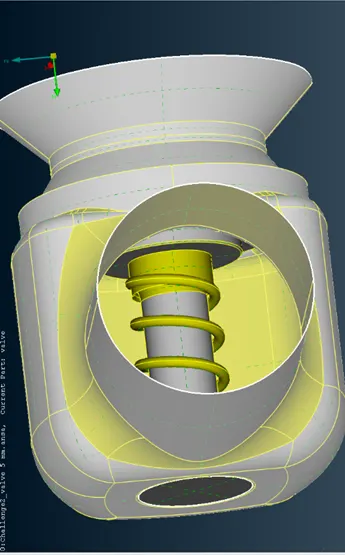
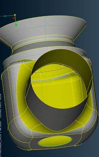
Suppose we need to Retrieved/ return that surface which is been deleted by us, TOPO _ > Faces _ > Click Undelete _ > In the model the surface/plane which is deleted by us is displayed in white colour and the green cross edge _ > After Clicking the Cross edge then the deleted surface is retrieved and it can be shown in light green colour, which can be seen more clearly by control+shift and enable the shadow, After doing this we should select the Face _ > Click TOPO _ > Select the surface which is seen in light green colour and then click centre button
Step 4:- Meshing
- Now going for the mesh option here we are considering the following terms,
Case- 1
- Target length = 1 mm
- Element type = Tria
Case- 2
- Target length = 3 mm
- Element type = Tria
Case-3
- Target length = 5 mm
- Element type = Tria
Result:
Case No: - 1
- Target length = 1 mm
- Element type = Tria
Select Classic MESH tool - > In that we had to go in perimeters after then click on Length.
- > choose the perimeters and to select the whole model we have to drag down the cursor and select the whole model, later we had to click the mouse centre button - > In length we have to give the number 1 as shown below in the picture
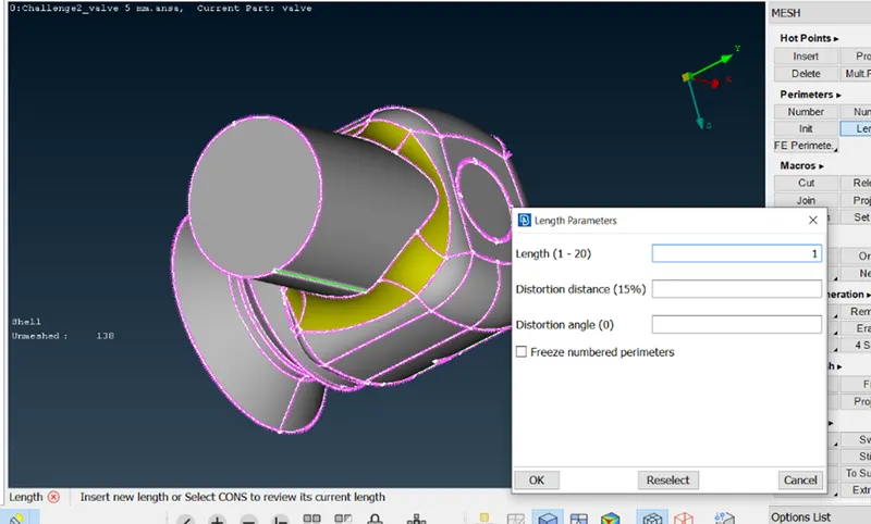
> Since after doing this for perimeters we are going to do exactly similar for macros.
Since we are moving for a mesh parameters and Quality criteria.
Select Mesh parameter - > In basic we had to choose the element type has TRIA and in mesh size the target length should be 1 as per these assignment.
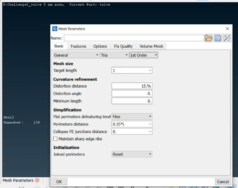
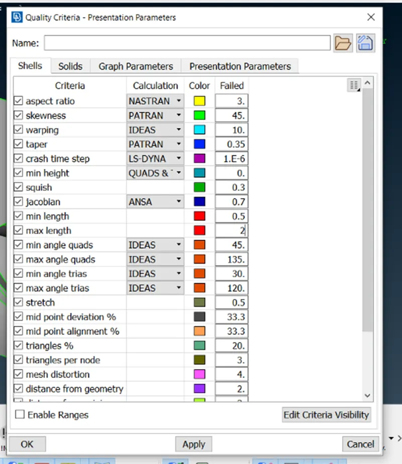
Quality criteria _ > Tick all the parameters as shown in below picture _ > Minimum Criteria should be 0.5mm and maximum Criteria should be 2mm _ > Click on Apply.
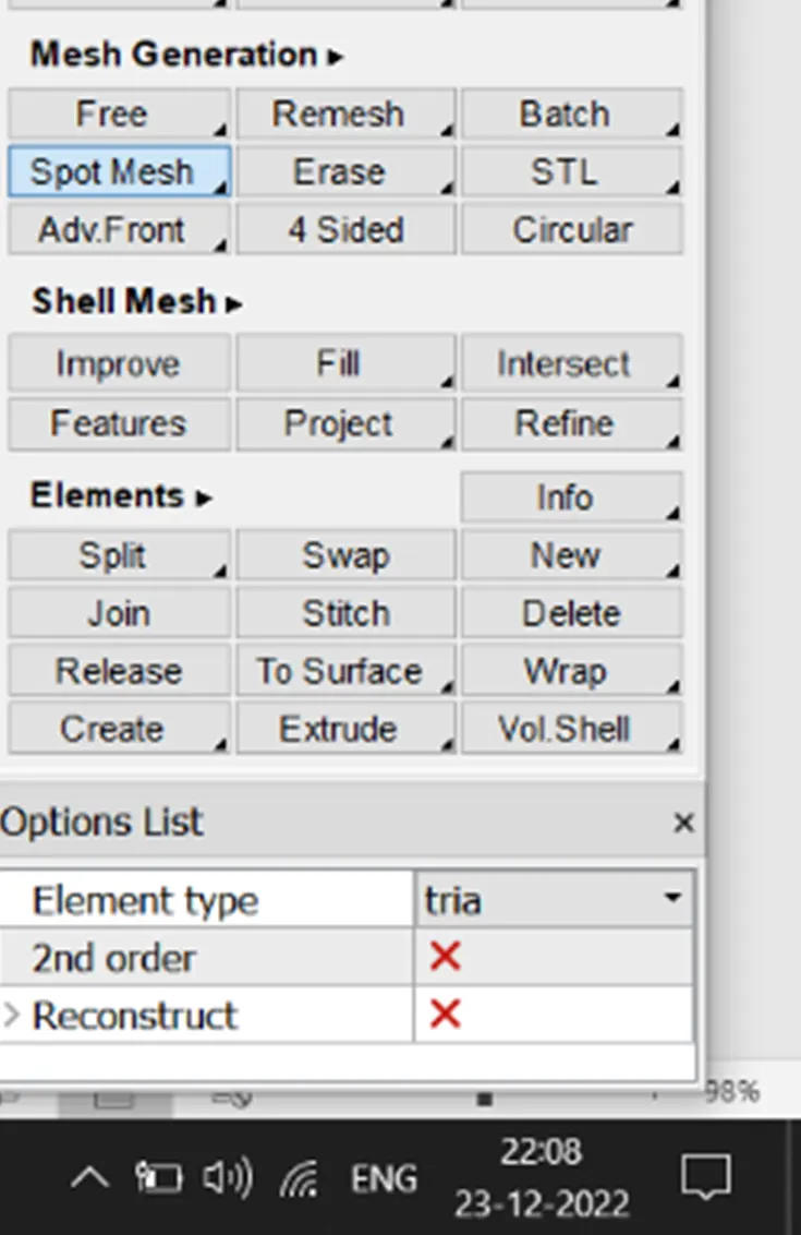
- Now using Spot mesh to provide the meshing for the given model.
For Spot mesh _ > Mesh generation _ > spot mesh
Meshed Element with the target size of 1mm
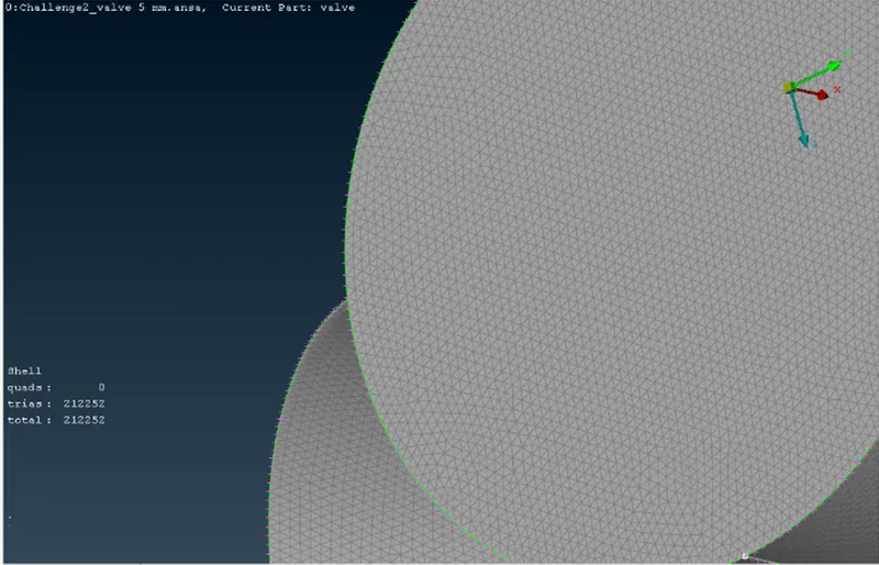
The total no of elements under 1 mm is 212252.
Case No: - 2
- Target length = 3 mm
- Element type = Tria
Select Classic MESH tool - > In that we had to go in perimeters after then click on Length.
- > choose the perimeters and to select the whole model we have to drag down the cursor and select the whole model, later we had to click the mouse centre button - > In length we have to give the number 3 as shown below in the picture.
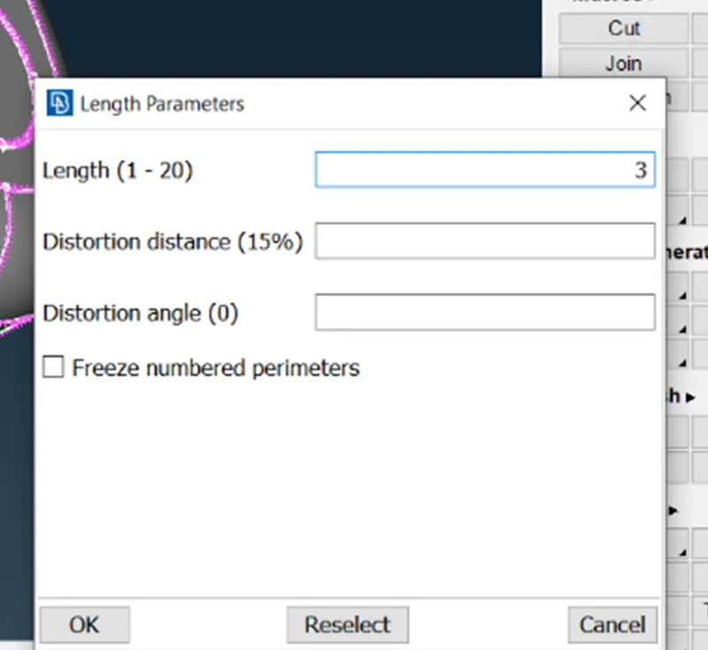
> Since after doing this for perimeters we are going to do exactly similar for macros.
Since we are moving for a mesh parameters and Quality criteria.
Select Mesh parameter - > In basic we had to choose the element type has TRIA and in mesh size the target length should be 3 as per these assignment.
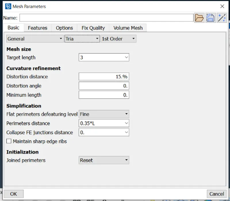
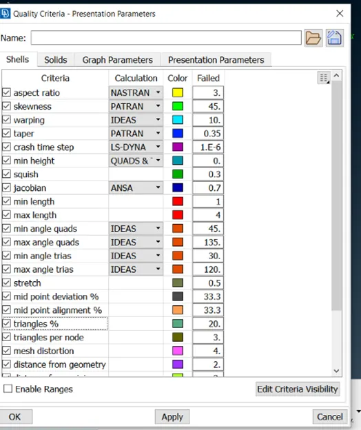
Quality criteria _ > Tick all the parameters as shown in below picture _ > Minimum Criteria should be 1mm and maximum Criteria should be 4mm _ > Click on Apply _ > OK
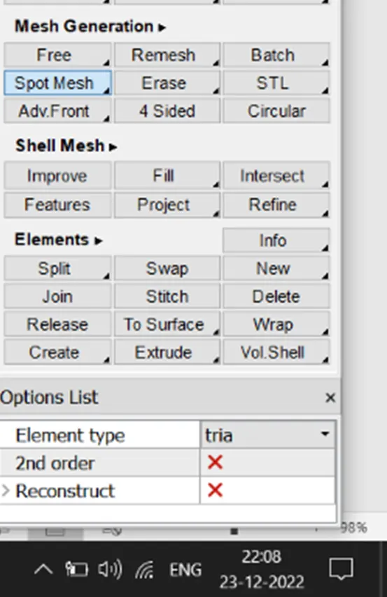
- Now using Spot mesh to provide the meshing for the given model.
For Spot mesh _ > Mesh generation _ > spot mesh
Meshed Element with the target size of 3 mm
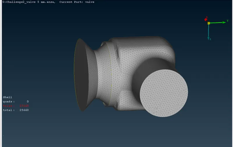
The total no of elements under 3 mm is 25660.
Case No: - 3
- Target length = 5 mm
- Element type = Tria
Select Classic MESH tool - > In that we had to go in perimeters after then click on Length.
- > choose the perimeters and to select the whole model we have to drag down the cursor and select the whole model, later we had to click the mouse centre button - > In length we have to give the number 5 as shown below in the picture.
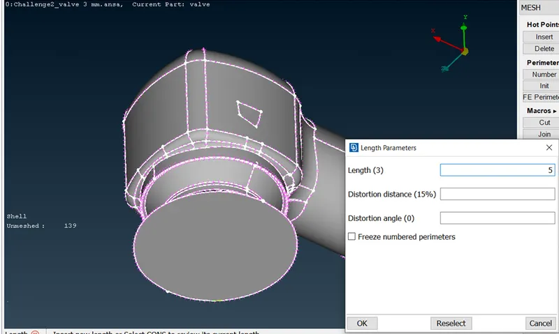
> Since after doing this for perimeters we are going to do exactly similar for macros.
Since we are moving for a mesh parameters and Quality criteria.
Select Mesh parameter - > In basic we had to choose the element type has TRIA and in mesh size the target length should be 5 as per these assignment.
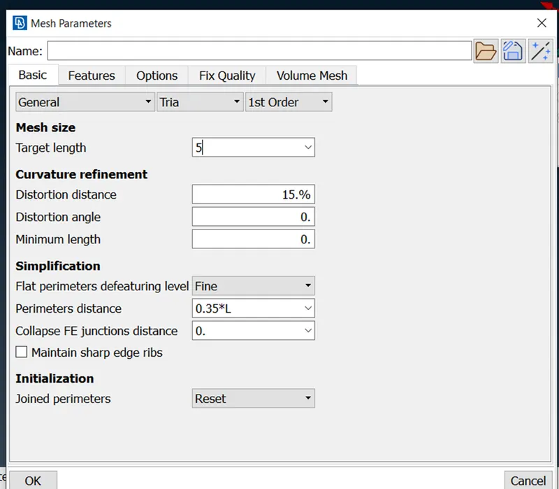
Quality criteria _ > Tick all the parameters as shown in below picture _ > Minimum Criteria should be 1mm and maximum Criteria should be 7mm _ > Click on Apply _ > OK
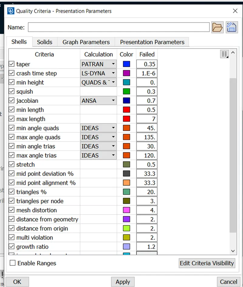
- Now using Spot mesh to provide the meshing for the given model.
For Spot mesh _ > Mesh generation _ > spot mesh
- Meshed element with the target length size is 5 mm, but the inside the model the following parts like column, spring, Valve head, base surface are not meshed properly as shown below in the picture, so for these we will be meshing target length size is 1 mm.
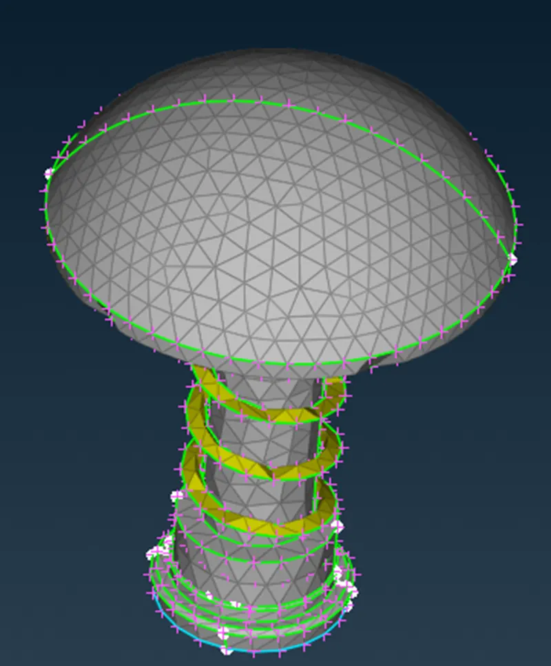
Click Lock model tool _ > erase the old mesh by selecting the erase tool which is present under the mesh generation, we have to drag down the cursor and select the whole model, later we had to click the mouse centre button to apply that command.
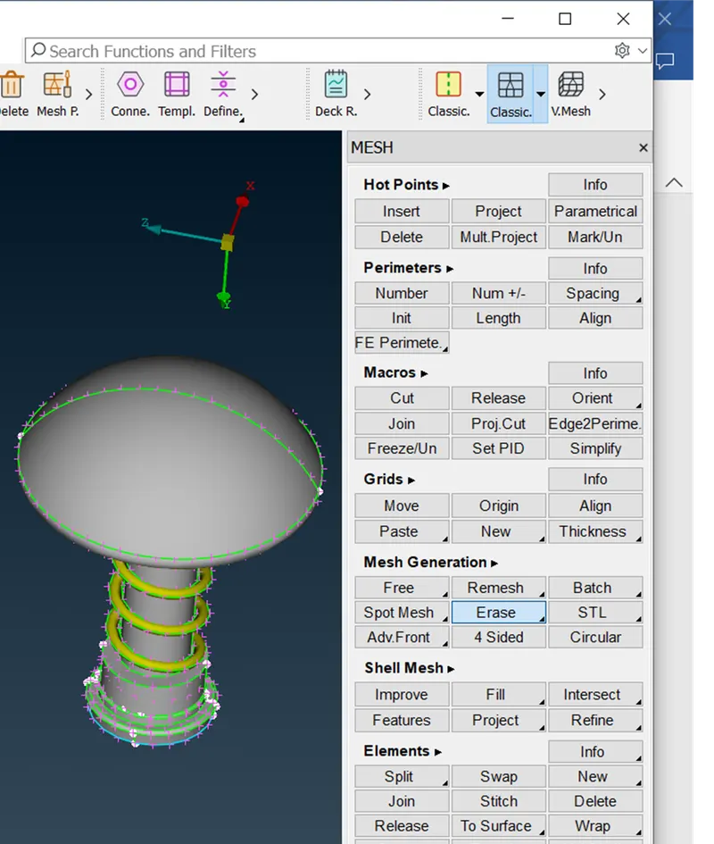
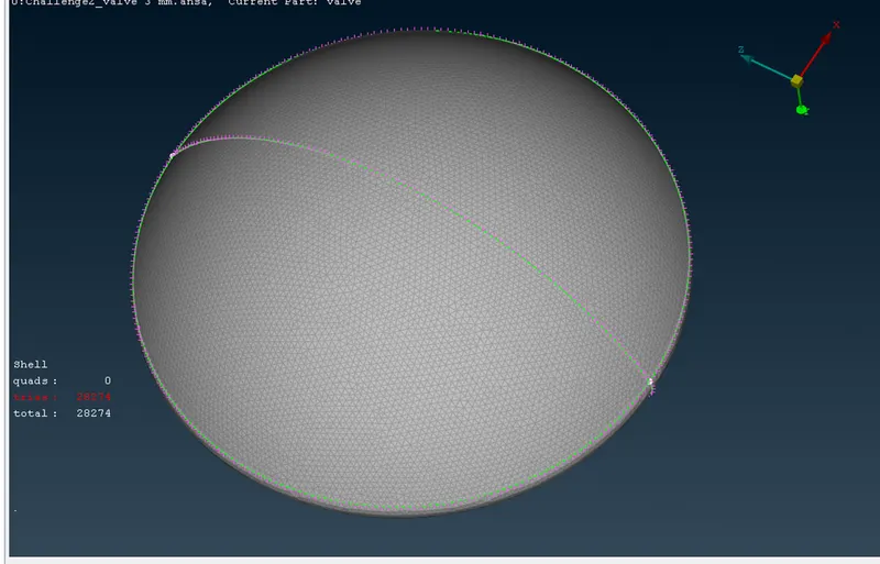
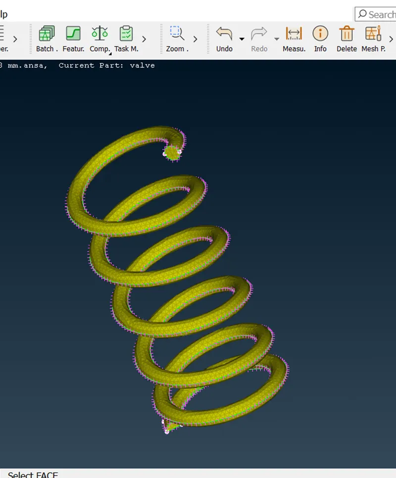
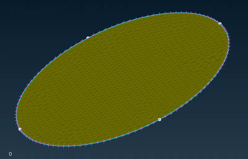
Now mesh this parts by dividing the model like saved in properties, by using the same procedure what we had one in the case 1 or 2,
- Valve head
- Spring
- Base surface
- Column
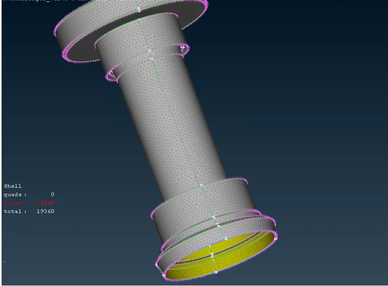
Meshed Element with the target size of 5 mm
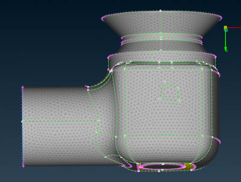
The total no of elements under 5 mm is 79115.
Learn in this challenge: -
In this challenge I have learned how to create a PID , Assign PID , Geometric errors to check and how to solve this error , meshing and the tools like OR , NOT , AND & etc and also learned how to mesh inner model.
Conclusion:-
Here finally we have meshed the given Valve model. You can also see the number of elements meshed in the model as shown above, in this as the target length increase the accuracy gets comprises, we can say that target length is inversely proportional to accuracy.
https://drive.google.com/drive/folders/1NN-dOsuAdc1x9r2KNfYIPLkBTHcWWCkG?usp=share_link