Week 4 - CHT Analysis on Exhaust port
AIM: To perform the steady state CHT simulation on the exhaust port
CHT: It is basically stands for the conjugate heat transfer, it is basically a mathematical model, which is mainly used to understand the heat transfer phenomena between the body and fluid flowing over or inside the surface.
it is mainly used in the application of heat exchanger, cooling or heating of electronic equipment, and for general purpose too.
In the given problem, two modes to heat transfer takes place, firstly the convection, which is between the fluid and solid surface, and conduction, which takes within the wall of exhaust surface.
Procedure for Analysis:
- The exhaust port imported to the space claim, initially, repair operation has been performed, to remove the duplicate edges, afterwards, volume has been extracted by using prepare tab
- Then we rename the fluid volume and solid volume, and activate the share topology, as a result we get the conformal mesh generated between the solid and fluid volume
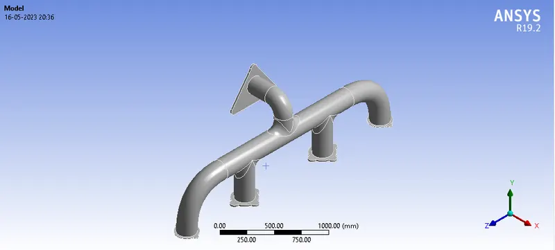
Fig: Model View
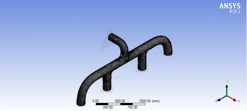
Fig: Mesh View
In meshing we had added a inflation layer having max thickness of 5mm and no. oflayers to be 5 and growth rate to be 1.2
The stats of the Mesh are:
Node:131466
Elements:475920
- Afterwards, after generating mesh, we entered the setup tab, in which i used the pressure based and steady state for analysis
- Under the tab of setting up physics, we opt on for energy equation, and choose k-epsilon as viscous model, assuming turbulent flow, choosing air a material for fluid and Al for solid,
- Boundary Condition: Inlet velocity = 5m/s, T= 700K
For outer wall: Thermal convection set to H=20W/m^2k - Finally, run the simulation by initialising the hybrid, and then press the calculate tab for around 150 iterations
Set the post processing contour for temperature contour for Inlet, Outlet, and outer wall convection
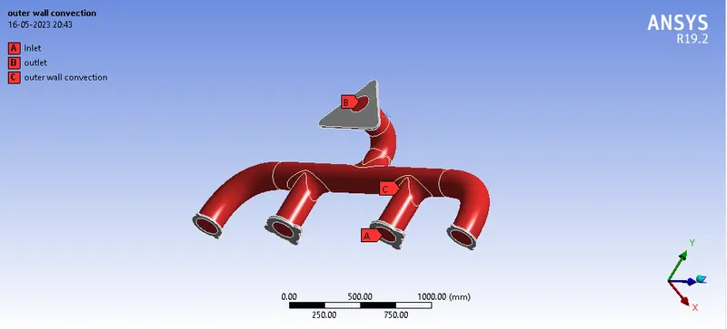
Fig: Name Selection
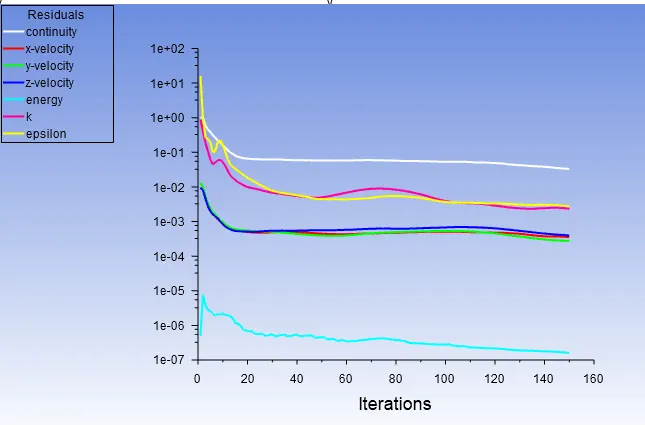
Fig: Residual Converges to about e-03 at around 20 iterations
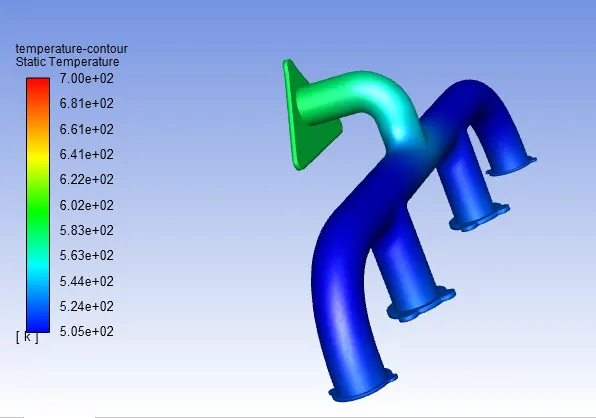
Fig: Depicts the temperature profile of exhaust system
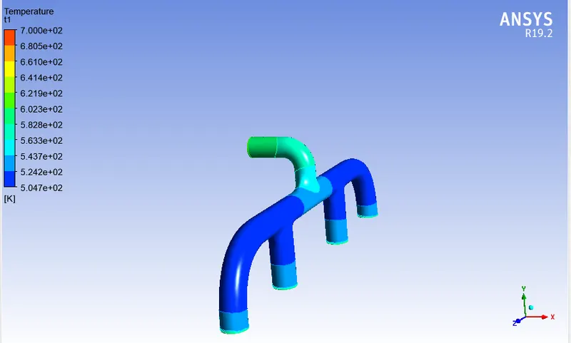
Fig: Temperature Profile, as it is witness that, temperature at the outer end is higher as compared to the inlet end, due to high velocity at the outlet as to maintain the law of continuity (mass conservation) in our space as velocity increases, reynold no. increases, as a result friction and temperature increases
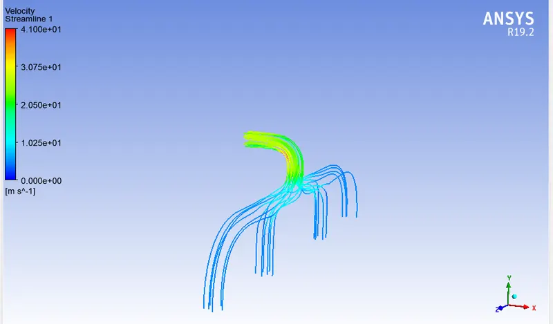
Fig: Depicts the velocity contour, as witnessed that, velocity is higher at the outlet as compared to inlet, due to law of conservation of mass.
The following shows the outer wall Surface Heat Transfer Coefficienct:
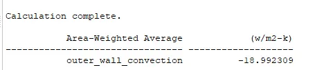
Therefore, the computation value of heat transfer coefficent is 19 W/m^2-k
The following is the analytical solution of same model:
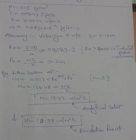
Therefore the value of analytical solution and computational solution is almost similar, the finer accuracy of result is obtained due to finer mesh