Week 4 - CHT Analysis on Exhaust port
AIM:-
The aim of this project is to simulate the conjugate heat transfer simulation inside an exhaust port.
OBJECTIVE:-
- Need of simulating Conjugate heat transfer on exhaust manifold
- Calculation of wall heat transfer coefficient on internal solid surface
- Maintaining appropriate y+ value for turbulance model
CONJUGATE HEAT TRANSFER(CHT):-
The contemporary conjugate heat transfer model was developed after computers came into wide use in order to substitute the empirical relation of proportionality of heat flux to temperature difference with heat transfer coefficient which was the only tool in theoretical heat convection since the times of Newton. This model, based on a strictly mathematically stated problem, describes the heat transfer between a body and a fluid flowing over or inside it as a result of the interaction of two objects. The physical processes and solutions of the governing equations are considered separately for each object in two subdomains. Matching conditions for these solutions at the interface provide the distributions of temperature and heat flux along the body–flow interface, eliminating the need for a heat transfer coefficient. Moreover, it may be calculated using these data.
APPLICATIONS OF CHT:-
Starting from simple examples in the 1960s, the conjugate heat transfer methods have become a more powerful tool for modeling and investigating nature phenomena and engineering systems in different areas ranging from aerospace and nuclear reactors to thermal goods treatment and food processing, from complex procedures in medicine to atmosphere/ocean thermal interaction in meteorology, and from relatively simple units to multistage, nonlinear processes. The applications in specific areas of conjugate heat transfer at periodic boundary conditions and in exchanger ducts.
EXHAUST PORT SIMULATION:-
- Geometry
- Mesh
- Setup
- Solution
- Results
Geometry:-
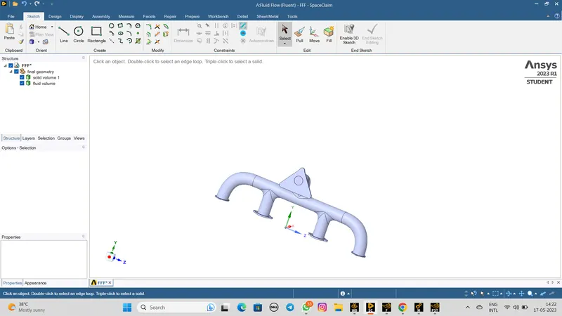
The first step is to import the geometry into spaceclaim and extract the fluid volume where the fluid interacts with the exhaust port.
MESH:-
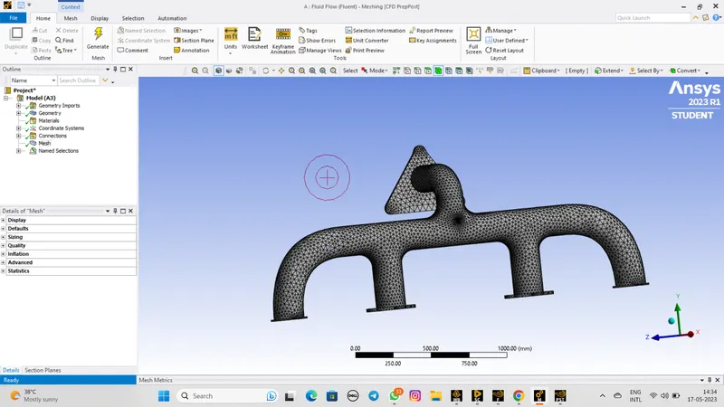
- Select the face selection tool > then select the faces > create named selection for inlet, outlet, outer wall convective, and interface inflation layer.
- Click on mesh > change element size to 150mm.
- In inflation, change the named selection to the created interface inflation layer > inflation option: first layer thickness > set the first layer height as 2mm which comes from wall y+ value.
- Right click mesh > insert > sizing > in geometry selection select the body > set the element size to 8mm (this gives the maximum number of elements) > set capture curvature on.
- Click generate. After it has meshed > click update.
SETUP:-
- We start with mesh check in domain>go to mesh>select check>wait for mesh checking resule.
- We will bw use a pressure-based model absolute velocity formulation for steady-state analysis.
- Go to model>turn on energy>in the viscous model set as K- epsilon.
- In the material the fluid material is sir and solid material is aluminum.
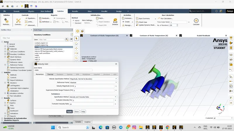
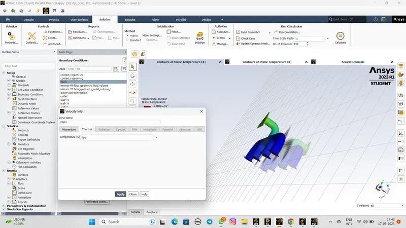
- Now set the boundary condition for inlet, velocity as 5m/s and thermal temperature is 700.
- The outlet will have a gauge pressure of a 0pa with 300k temperature
- The outer wall convection heat transfer coefficient is 20W/m^2k
SOLUTION:-
- We have to move to initialization and initialize using a hybrid method.
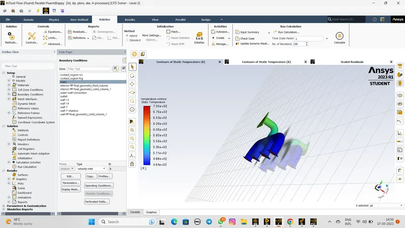
- Go to results>graphics>contours>new create a temperature counter at the inlet, outlet, convection wall and adiabatic surfaces.
- In solution > activities>create>select scene animation>then select the temperature contour as the enity
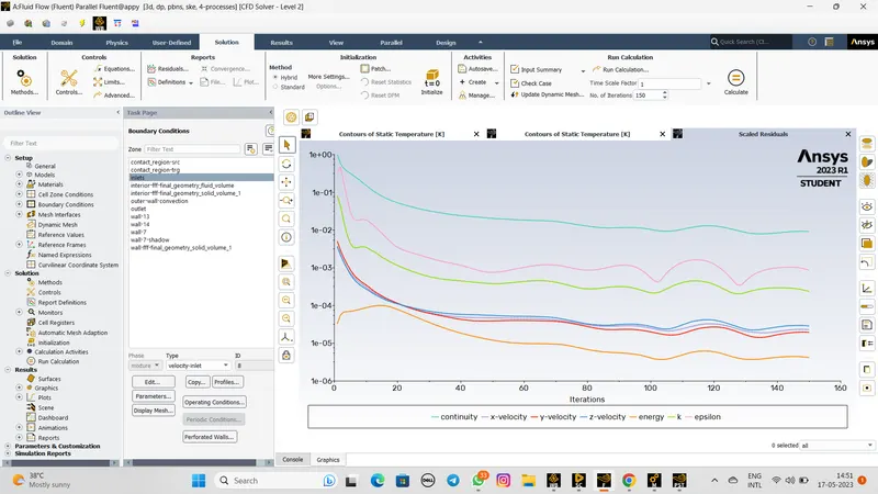
- Run the calculation for 150 iteration.
Result:-
The residuals plot as below,
The 150 iteration result as below,
TEMPERATURE Contur:-
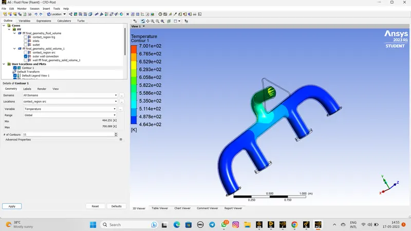
The temperature at the mid plane of the direction of the flow.if we observed the three sectioned contours we observe that the temperature of the solid part in the cross section.
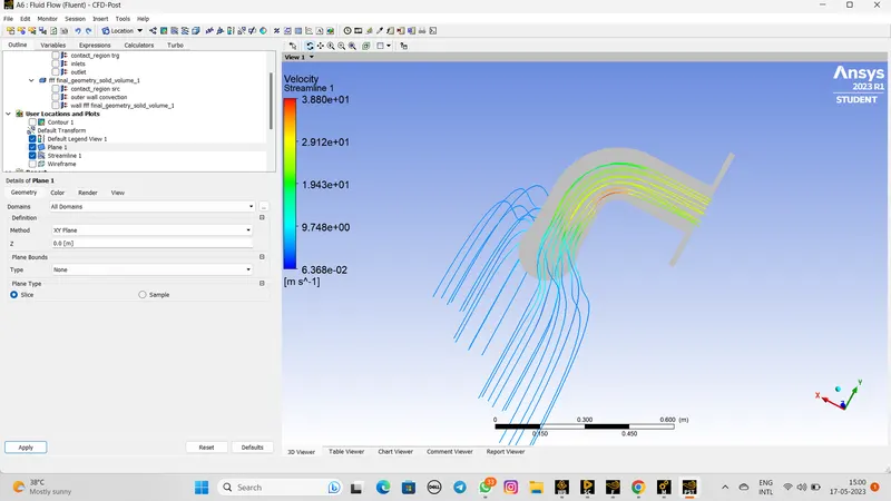
Velocity Contour:-
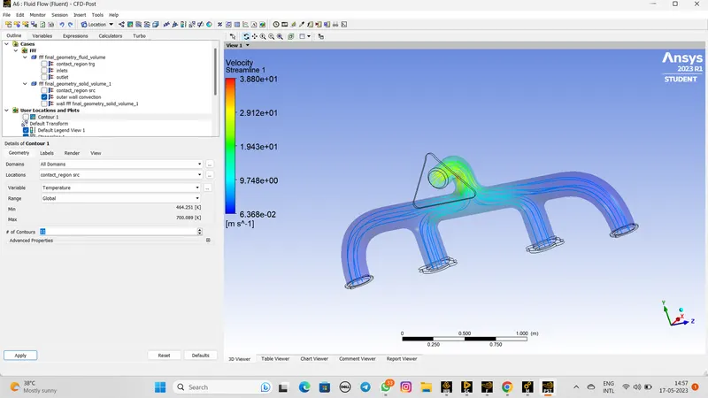
Here we can show the clear streamline at the outlet surface.
The velocity increases as we moved in the direction of the flow.whem we observe the contour at the exhaust port then we see that at the entrance region the velocity is the least ans as the flow both directions in the exhaustport.
Heat transfer coefficient:-
CONCLUSION:-
- The simulation of the conjugate heat transfer analysis is done.
- The heat transfer coefficient is calculated at the wall surface.
- As we increased the mesh count the CHT analysis the accuracy of the heat transfer increase.