Week 4 - CHT Analysis on Exhaust port
ANSWER:
Aim:
CHT analysis of given exhaust port model.
Objective:
Brief description of why and where a CHT analysis is used.
To generate mesh with suitable named selection.
Simulate heat transfer through exhaust port model by using suitable solver and boundary conditions
Calculate the wall/surface heat transfer coefficient on the internal solid surface.
To plot Velocity and Temperature contours at different sections of exhaust port.
Verify Accuracy of predictions obtained from simulatiom.
Theory:
What is CHT Analysis,its Usage and importance:
CHT stands for conjugate heat transfer.It is used where both heat transfer in fluids and solid takes place simultaneously.
Since these are two different phenominon and two different physics involved in both type of the heat transfer,hence factors affecting both types of heat transfer is taken into consideration.
Heat transfer in solid takes place through coduction that is molicules do not have to leave their place to transfer heat.Heat transfer tin fluids takes place through convection in which molicular as well as particle movement happens during heat trasfer.
Practicle situations whenre conjugate heat transfer happens are heat exchangers, heaters, coolers etc where a hot or cold fluid flowing on a solid surface transfer heat with the fluid through convection and at iterface of solid and liquid heat is transferred through conduction surface through .
Dimensionless Numbers associated with conjugate heat transger:
Nusset Number(Nu):
It is the ratio of covective heat trasferred to the heat transfer through conduction.Based on Nusset number value dominating nature of mode of heat transfer can be assessed.
If Nusset no is then heat tranfer is purely through coduction.It is clossely related to Rayleigh Number .
In free convection(buonancy driven flow) Nusset is function of Rayleigh number and Prandtle Number,while in forced convection Nusset Nusset Number is function of Reynold Number and Prandtle Number.
Rayleigh Number(Ra):
It is defined as the product of Grashoff number and prandtle number.
Ra=Gr*Pr
Grashoff Number(Gr):
It is defined as the ratio of buoyancy force to viscous force.It is analogous to Reynold Number and used in free convection.
Reynolds Numbe(R):
It is defined as the ratio of inertia force to viscous force.It is associated with forced convection.
R=ρ*V*d/μ
μ=visc
Prandtle number(Pr):
It is defined as the ratio of momentum diffusivity to thermal diffusivity. Empirical formula for Prantle number i
Heat Transfer through Convection:
Heat transfer through convection can be written using Newton's Law of cooling.
q=hA(Ts-Tf)
h=Heat transfer coefficient
Heat TransferThrough conduction:
Heat transfer through conduction can be calculated using Fourier's Law of conduction.
Q=kA∂t/∂x
k=Thermal Conductivity
Y+ Value:
To check if the mesh is fine enough to catch the boundary layer near the walls, a measurement called y+ describing a dimensionless wall distance is often used.
y+ =(y*.u*)/ν
u∗ is the velocity at the wall
y∗ - cell length at the wall
ν - kinematic viscosity.
The grid quality, as mentioned above for y+, is another important measurement. The wall boundary layer, for viscous simulations, should be meshed according to the y+ equation and is the finest meshed area in the grid and we need to ensure that our y+ values are within a certain range. It's important to ensure Y+ values are not so large that the first node falls outside the boundary layer region. If this happens, then the wall functions used by the turbulence model may incorrectly calculate the flow properties at this first calculation point which will introduce errors into pressure drop and velocity results.
Exhaust Manifold:It is an assembly designed to collect the exhaust gas from two or more cylinders into one pipe. The passage in the cylinder head which connects the exhaust valve and the exhaust manifold . The exhaust gases pass through the port to the exhaust manifold or header . On two-stroke engines the exhaust port is cut into the cylinder wall because it does not have valves.
Inefficiencies generally occur due to the nature of the combustion engine and its cylinders. Since cylinders fire at different times, exhaust leaves them at different times, and pressure waves from gas emerging from one cylinder might not be completely vacated through the exhaust system when another comes. This creates back pressure and restriction in the engine's exhaust system that can restrict the engine's true performance possibilities.
Geometry:
file >open>import
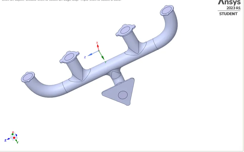
After Volume Extraction:
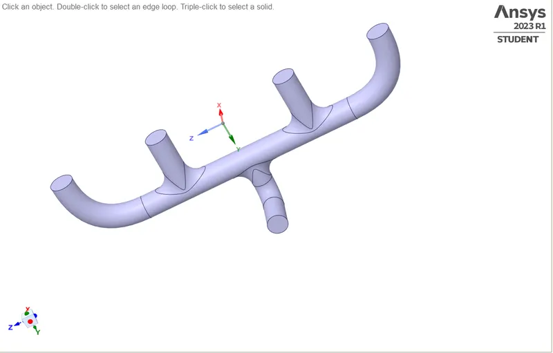
Extract volume using Extract Volume in Prepare.Rename this as fluid volume. Move this component into a new component and delete empty component
Mesh:
The K-omega turbulence model with varied mesh refinement is used to perform mesh dependent study.
| Solid volume Mesh Method | sizing(body sizing) | Element size = 15mm |
| Fluid volume | Element size = 150mm | |
| Y value (Height of first cell centroid from the wall) | 0.00028m | y+ value=5 |
| Number of inflation layers | 5 | -- |
| Growth rate | 1.2 | -- |
| Inflation type | First Layer Thickness | 0.00028m |
| Total number of cells | 439486 | Fine |
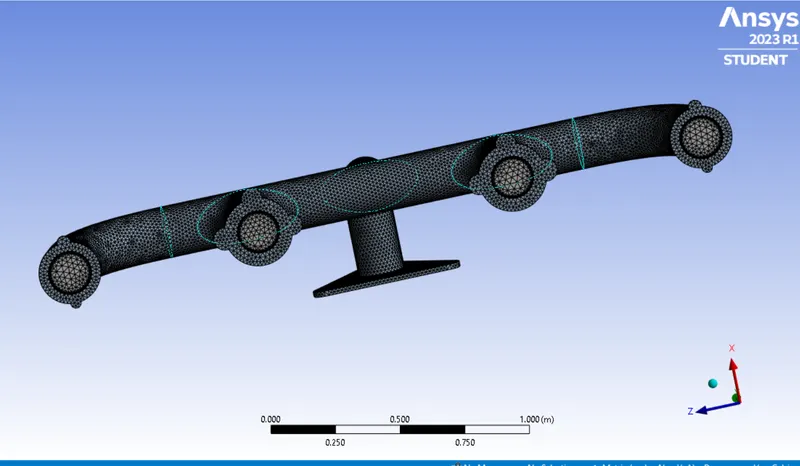
Inflation-Layer:
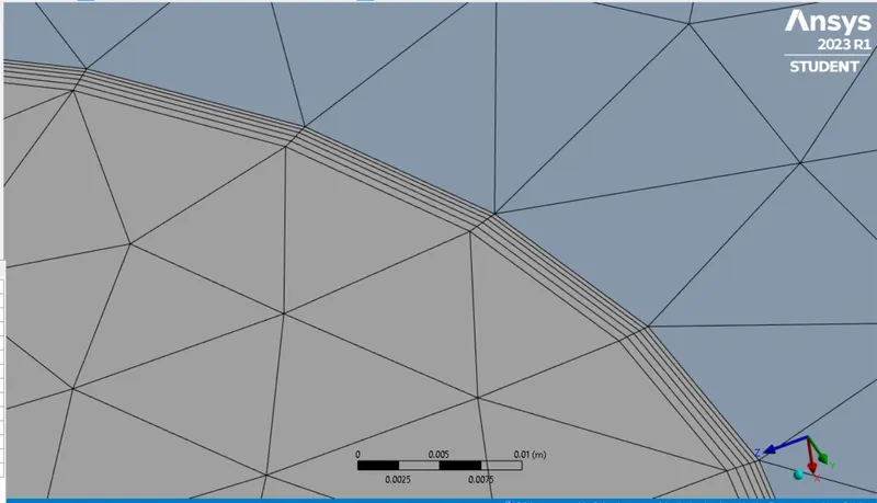
Mesh Quality:
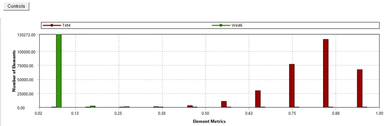
1. Naming the geometry as to inlet(there 4 ports as inlet), outlet, outer wall convection and inflation layer
2. Then mesh the model with an element size of 150mm.
3. For the solid Volume use the body sizing of an element size of 15mm.
4. Then add inflation on fluid volume surface whis is named as Inflation Layer choose 5 layers and provide first layer thickness of 0.00028m.
6. Finally check for the mesh quality.
Solution and Results:
The simulation set-up will be using Y+ value of 100 and mesh with K-omega SST turbulence model.
- The K-omega model is well suited When near wall region is much of importance to capture behaviour.
- k-omega (SST-Shear Stress Transport) can be used in this case because of it's capability to incorporate high Reynolds number flows. As it uses K-omega in the inner region of the boundary layer
- The mesh refinement is an important aspect in K-omega model as it accounts for near-wall effects. The Y+ J/kg values should be in the range between 1≤Y+≤101.7894e−5. Mesh refinement should be much fine enough to capture near-wall effects. Accordingly, it uses extensive computation resources for such fine mesh refinement.
Solver and Boundary Conditions :
|
SETUP |
||
|
Solver Type |
pressure - Based |
|
|
Velocity Formulation |
Absolute |
|
|
Time |
|
|
|
Viscous Model |
K-omega SST | |
|
Material |
Fluid volume: Air solid volume:Alluminiam |
|
|
Cell zones ff_final-geometry_fluid- volume ff_final-geometry_solid- volume |
Fluid type: Air | |
|
Boundaries |
Inlet (velocity inlet) Velocity Magnitude 5m/s Turbulence(Turbulence intensity-5% haudraulic diameter(0.16611) Temperature – 700K Outlet x (Pressure outlet) Gauge Pressure – 0 pa. Turbulence(Turbulence intensity-5% haudraulic diameter(0.16611) Temperature=300k Outer wall convection-(wall) Thermal condition-Convection heat transfer coefficient(20 w/m^2K) and Free stream temperature(300k) solid geometry wall Thermal condition-heat flux heat fux value=0 |
|
|
Reference values |
Projected Area = 0.8 m^2 Density = 1.225kg/m^3 Enthalpy = 0 J/kg Pressure = 0 pa Temperature = 700K Velocity = 5m/s Viscoity = 1.7894e^-5 kg/m-s diameter-0.16611m |
Scale Residuals:
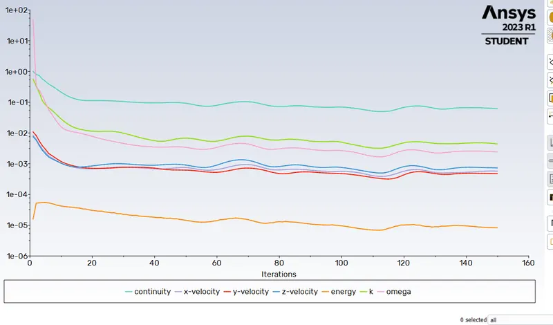
Mass Flow Rate:
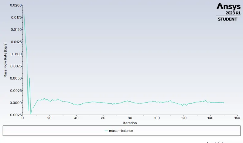
Area Weighted Average of Temperature:
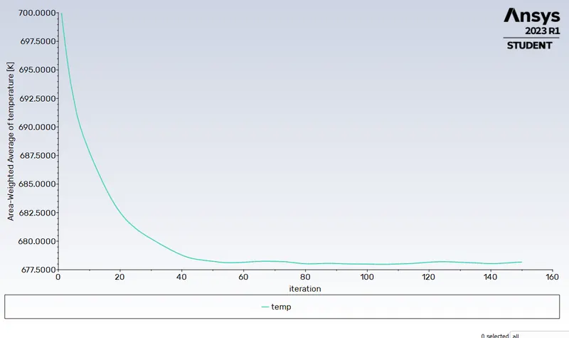
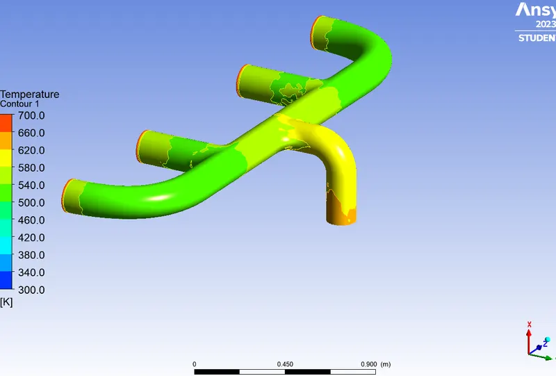
Temperatutre Contour on Interface:
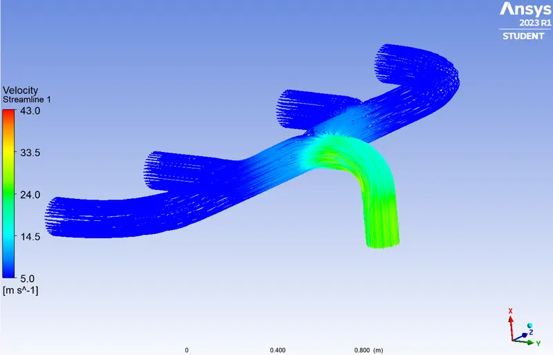
Velocity Streamlines in fluid region:
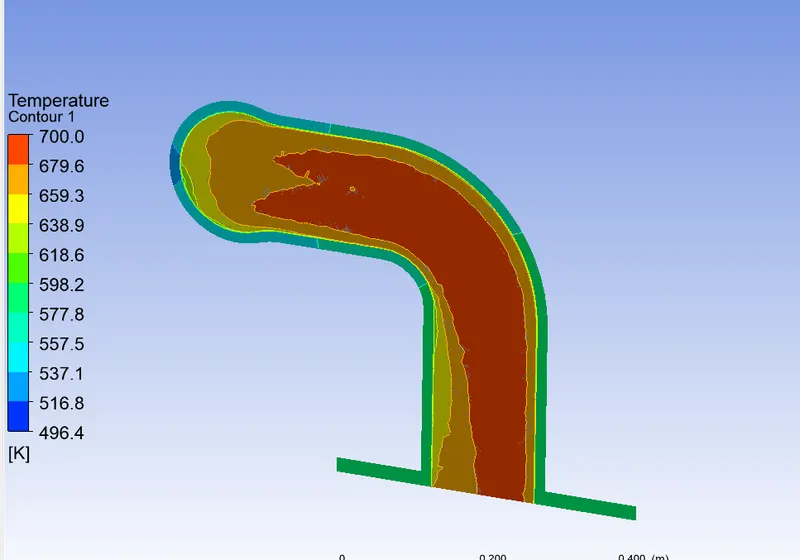
Teperature Contour on longitudnal Plane on outlet pipe:
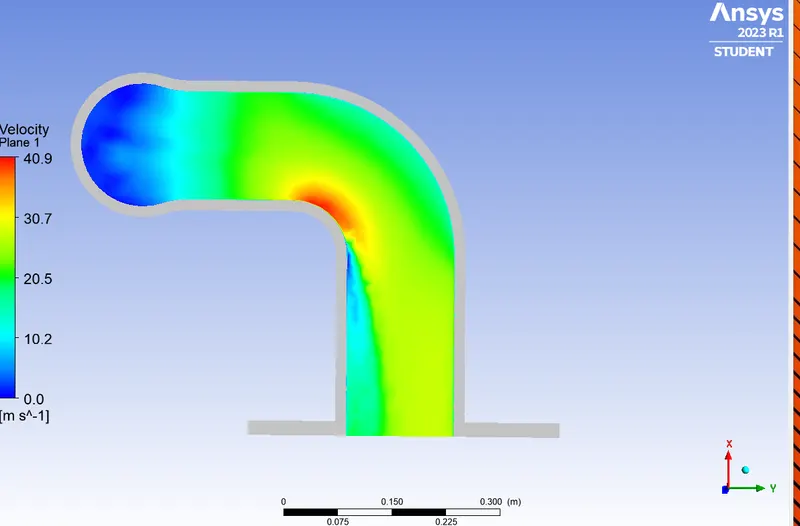
Velocity Contour Across the plane :
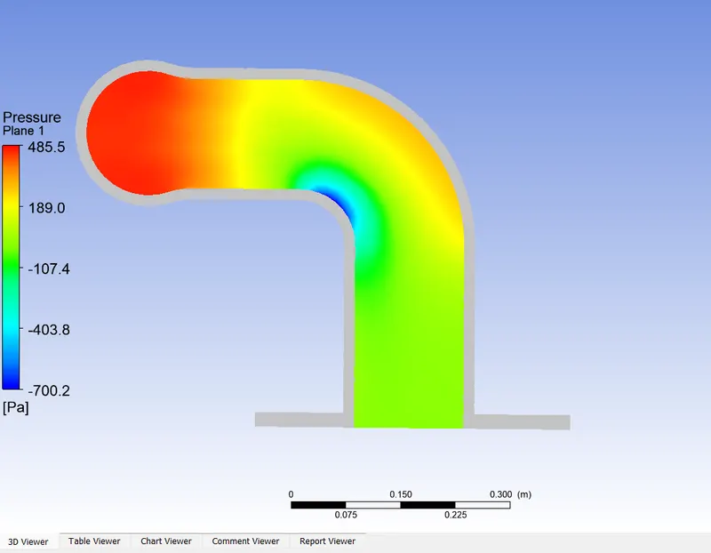
Pressure Contour :
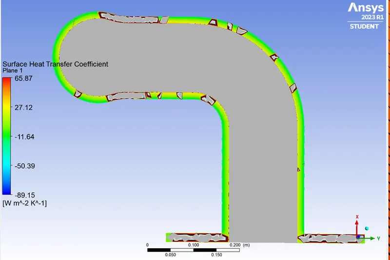
Surface Heat Transfer Coefficient:
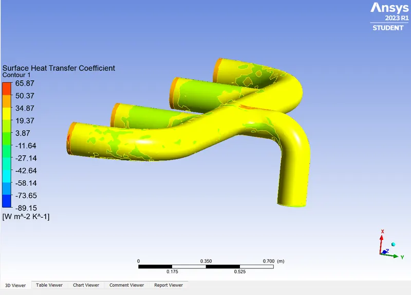
Surface Heat Transfer Coefficient:
Conclusion:
Maximum velocity can be seen at the corner point of bend where there is high pressure drop and heat transfer coefficient is maximum at this point as well hence there is maximum heat convection is happening in this region .
For same area mass flow rate is higher in outlet pipe hence overall velocity is high in this region leading to high rate of convection.
Further more fine mesh can be generated to get better view of behaviour of fluid .
Validation:
Accuracy depends foloowing factors
1-Right selection of grid size which is optimized to obtain better results.
2-Right selection of viscous model as k-omega gives better results near wall in boundary layers and k-epsilon model offer good results in free stream zone.
3-Right selection of Y+ value because if first cell point is beyond boundary layer then it will reflect results which are completly ooof no relevence.