Week 4 - CHT Analysis on Exhaust port
CHT(Conjugate Heat Transfer) anlysis.
The Conjugate heat transfer analysis is based on a mathematically structured problem, whixh should describes the heat transfer problems between a body(Solid domains) and a fluid(fluid domains) which flowing over or inside it. It allows as to describe the thermal exchange of energy at the interfaces between the domains. Conjugate heat transfer analysis can accurately predict heat transfer by simultaneous solving all the relevant solid and flow field heat transfer processes. One of the simplest ways to realize conjucation is through numerical methods. The boundary conditions for the fluid and solid interfaces is set and solved through iteration methods. Conjugate heat transfer is observed in many situations for example-Conduction through solids, free and forced convection in the gases as well as fluids and also for thermal radiations.
Conjugate Heat Transfer Applications(where CHT analysis is used?)
- Effective Heat transfer
- The fluid usually plays the role of energy carrier on large distances. Forced convection is the most common way to achieve high heat transfer rate. In some applications, the performances are further improved by combining convection with phase change (for example liquid water to vapor phase change).
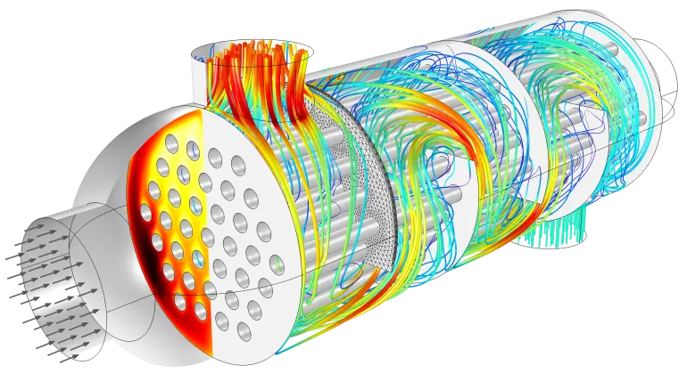
- Flow and temperature field in a shell and tube heat exchanger, illustrating heat transfer between two fluids separated by the thin metallic wall.
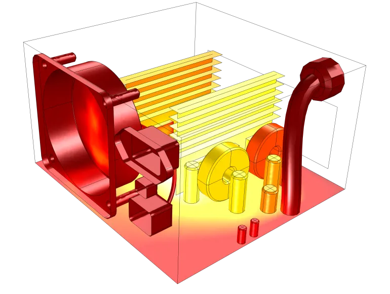
- Heat sinks are usually made of metal with high thermal conductivity (e.g. copper or aluminum). They dissipate heat by increasing the exchange area between the solid part and the surrounding fluid.
- Energy Savings.: Heat transfer in fluids and solids can also be combined to minimize heat losses in various devices. Because most gases (especially at low pressure) have small thermal conductivities, they can be used as thermal insulators, provided they are not in motion. In many situations, gas is preferred to other material due to its low weight. In any case, it is important to limit the heat transfer by convection, in particular by reducing the natural convection effects. Positioning of walls and use of small cavities helps to control the natural convection. Applied at the micro scale, the principle leads to the insulation foam concept where tiny cavities of air (bubbles) are trapped in the foam material (e.g. polyurethane), which combines high insulation performances with light weight.
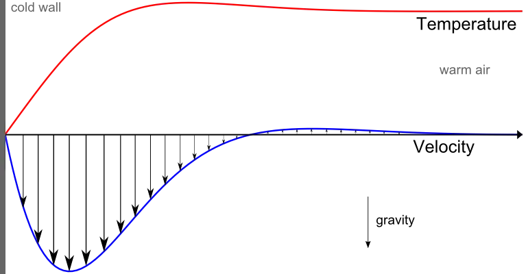
- Fluid and Solid Interfaces:-The temperature field and the heat flux are continuous at the fluid/solid interface. However, the temperature field can rapidly vary in a fluid in motion: close to the solid, the fluid temperature is close to the solid temperature, and far from the interface, the fluid temperature is close to the inlet or ambient fluid temperature. The distance where the fluid temperature varies from the solid temperature to the fluid bulk temperature is called the thermal boundary layer. The thermal boundary layer size and the momentum boundary layer relative size is reflected by the Prandtl number , for the Prandtl number to equal 1, thermal and momentum boundary layer thicknesses need to be the same. A thicker momentum layer would result in a Prandtl number larger than 1. Conversely, a Prandtl number smaller than 1 would indicate that the momentum boundary layer is thinner than the thermal boundary layer. The Prandtl number for air at atmospheric pressure and at 20°C is 0.7. That is because for air, the momentum and thermal boundary layer have similar size, while the momentum boundary layer is slightly thinner than the thermal boundary layer. For water at 20°C, the Prandtl number is about 7. So, in water, the temperature changes close to a wall are sharper than the velocity change.
Some others are;
- HVAC systems.
- Burners, combusters, electronic devices.
- Automotive, power plants and various other applications.
- Heat transfer in mobile phones.
- Drying of a porous flat plate.
- Heat transfer in ribbed passages.
- Heat transfer in micro-channels.
Geometry Set up
- Ansys Workbench software was launched and for the analysis system"Fluid flow (Fluent) was choosened.Based on the case which is to be anlaysed the project is renmaed.
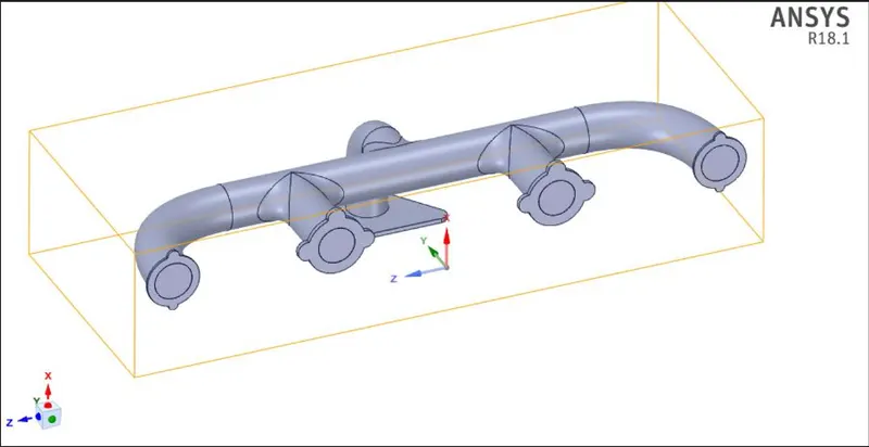
- Step file of the suitable case has to be selected and right click on the "geometry" and "import geometry" option is selected and loaded the geometry.
- After the geometry has to be loaded and then modify the geometry as per requirments.
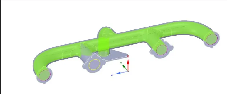
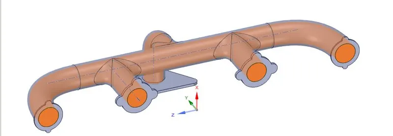
- Go to Repair and open Volume extract, and select the edges to separate inner and outer volume. Name the outer volume as Solid volume and inner ass Fluid volume and move bothe the volume to new component and delete empty components.
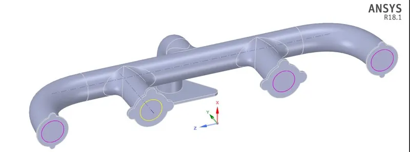
- Go to workbench and open Shareprep, to share the physics between the fluid and solid volume and conformal mesh can be achieved.pink circle are seen after completing the procces.

Mesh
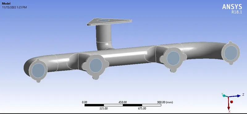
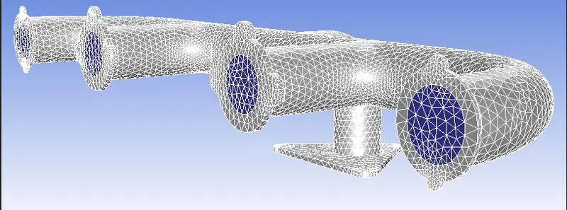
- Open the mesh tab and select the geometry and named the parts.
- Ansys fluent automaticaly add unnamed part as wall and adiabatic boundary condition is applied.
- Select the mesh and generate base mesh of default size
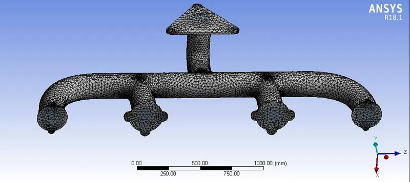

Nammed parts
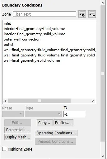
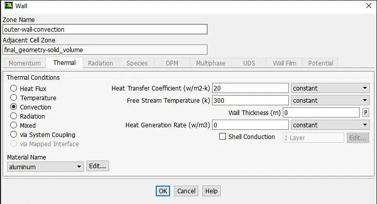
- Select the faces by using selecting face option then name the faces like ,Inlet, Outlet,outer-Wall-convection.
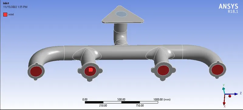
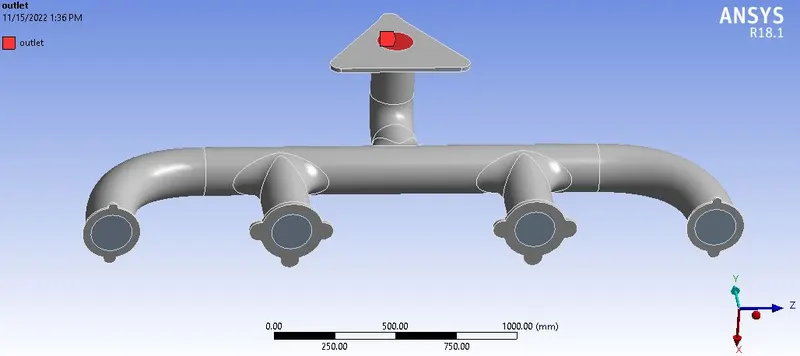
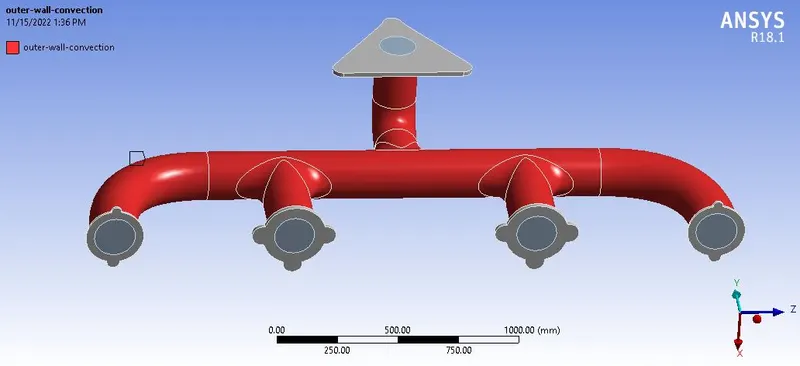
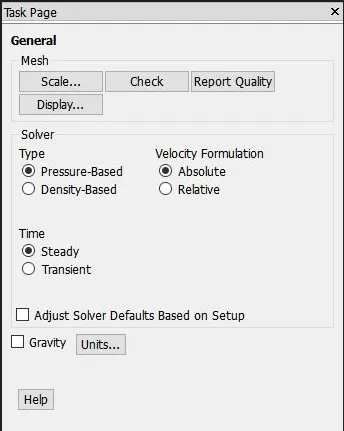
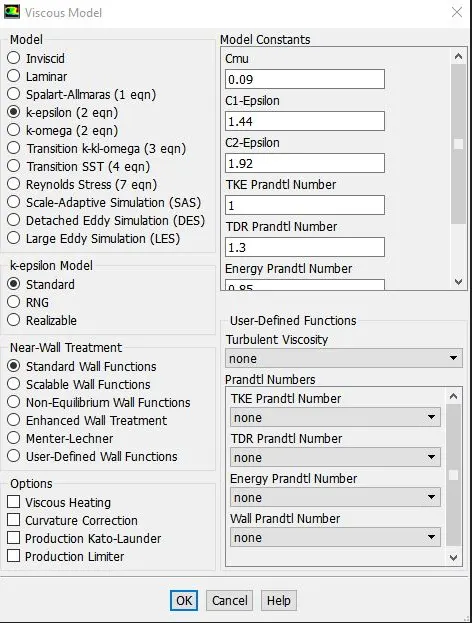
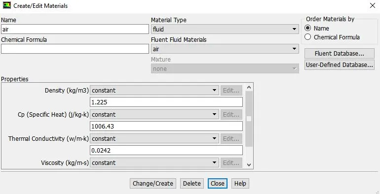
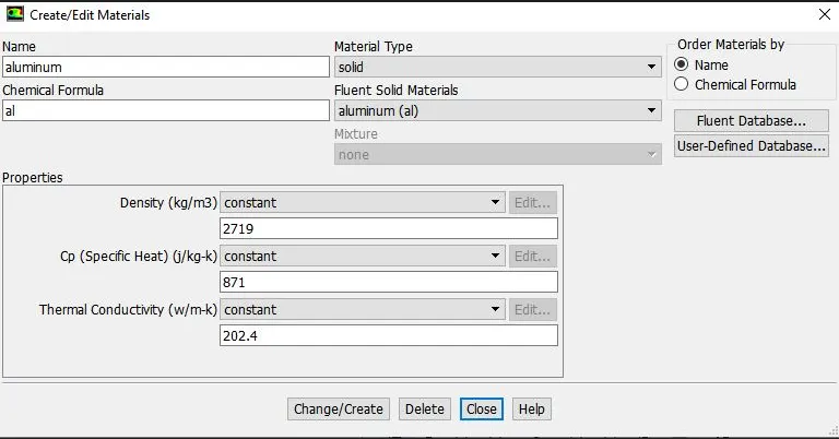
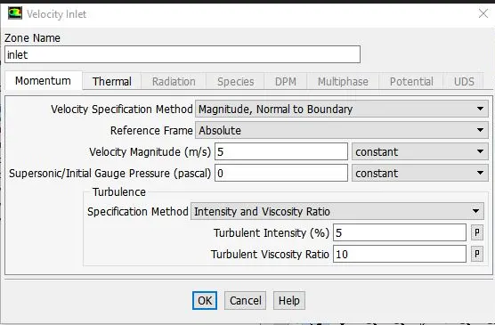
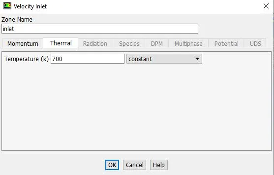
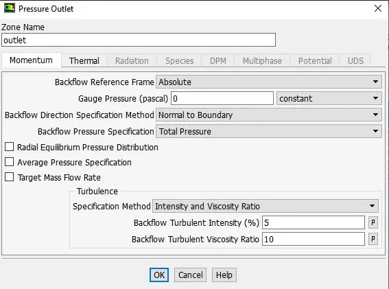
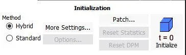
Set up
Results(Base line simulation)
Case-1 : Baseline simulation
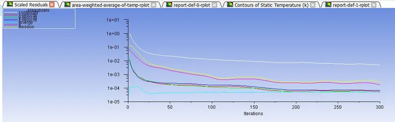
Residuals
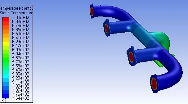
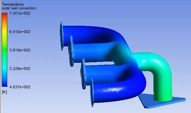
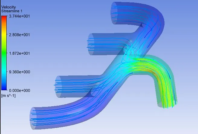
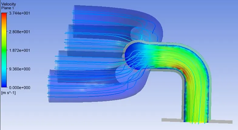
 '
'
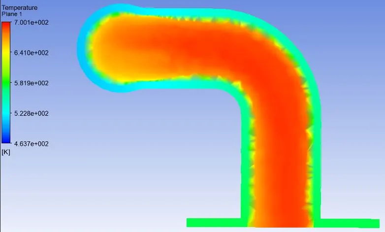
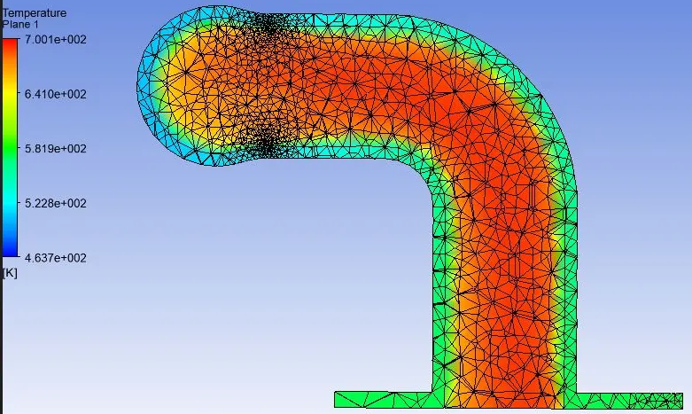
Case-1 : Refined simulation
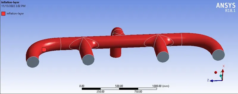
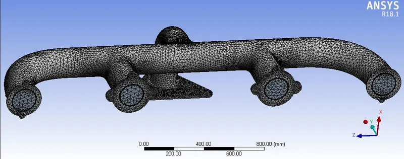
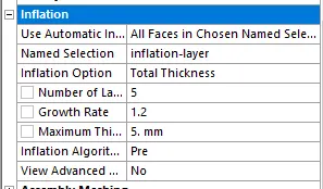
Mesh
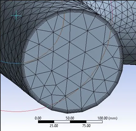
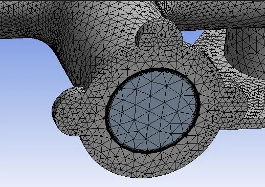
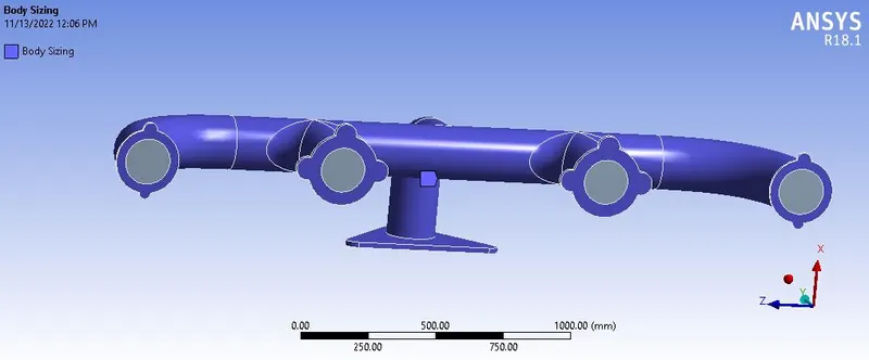
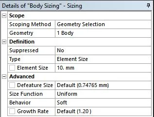

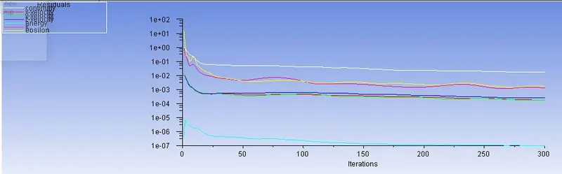
Residuals
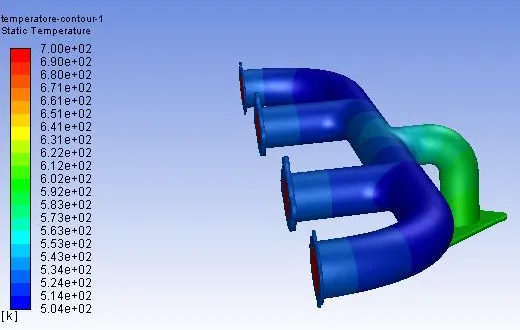
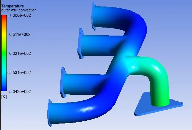
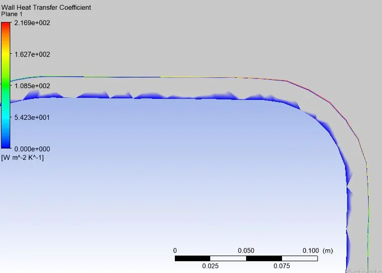
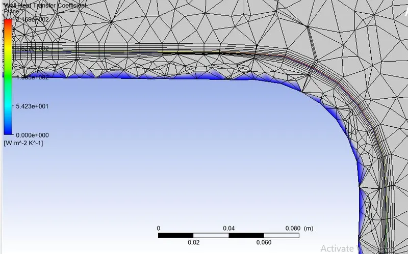
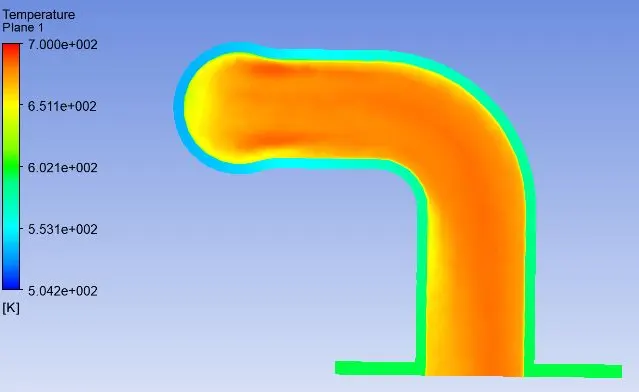
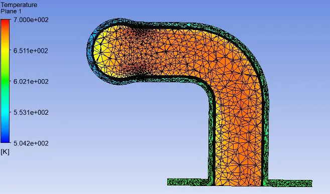
Verify if the HTC predictions from the simulations
- In thermal fluid dynamics, Nusselt number is the ratio of convective to conductive heat transfer at a boundary in a fluid.
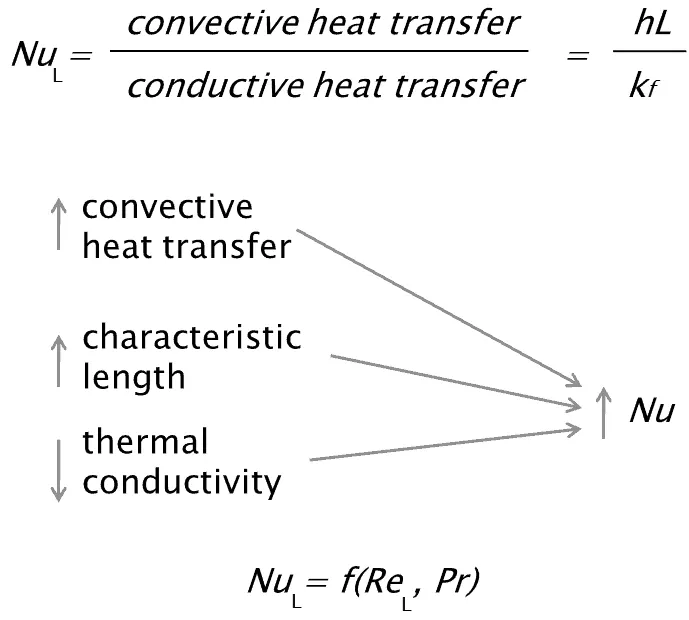
- h - Convective heat transfer coefficient.
- L - Characteristic length.
- k - Thermal conductivity of fluid.
NuD = 0.023 Re D4/5 Prn
The above equation shows the relation of nusselts number with Reynolds number.
where Reynods number Re is;
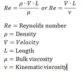
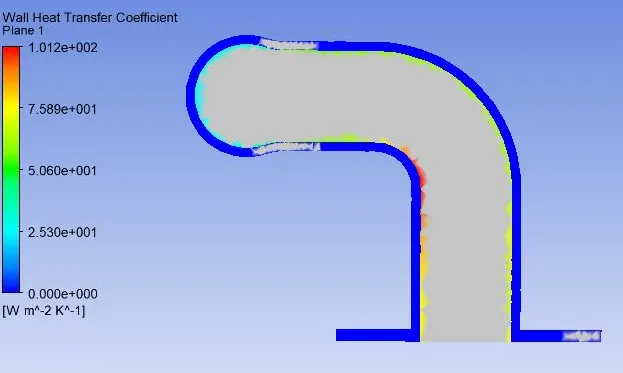
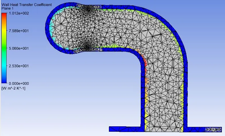
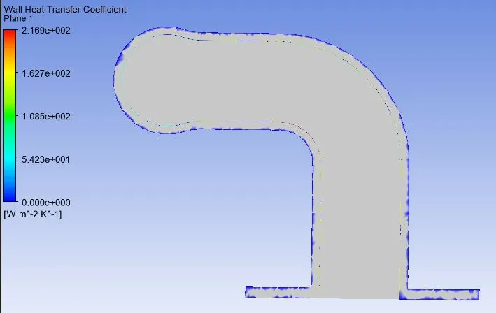
- The heat transfer coefficient is directly propotional to the Reynold number, which means propotional to the velocity. if there is an increase in velocity, then the convective heat transfer coefficient will also increases.
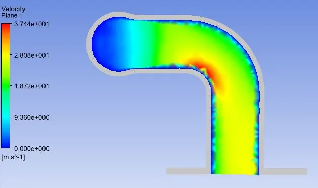
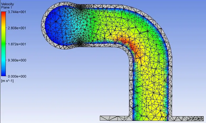
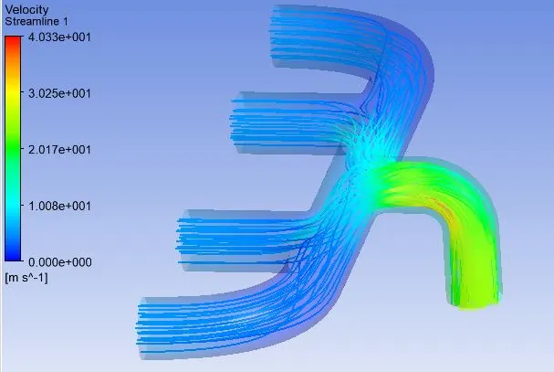
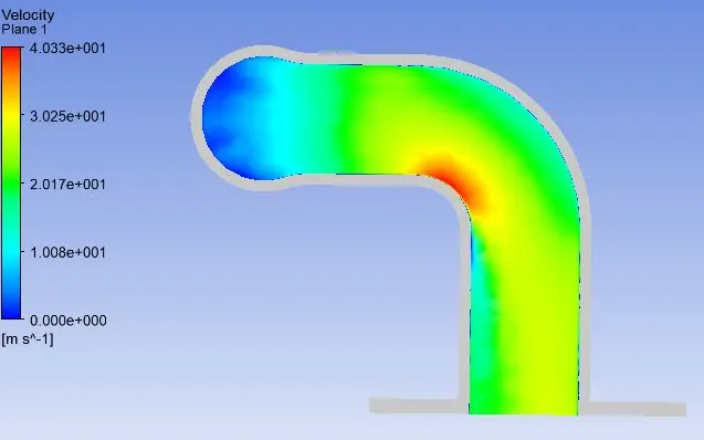
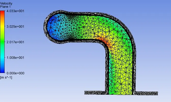
- While analysing the above simulations we can seen that the velocity is quite higher at the bend seection while comparing with other areas.
- Thus higher the reynold number, higher the heat transfer coefficient.
What factors does the accuracy of the prediction depend on?
Some of the factors that the accuracy of the prediction depends on;
- Share topology: Make sure that the share topology is set to share in ansys spaceclaim in geometry setup. Then only the case where the meshing is uniform and provides better connectvity.
- Mesh Quality: Accuracy of the simulation and its results will greatly depends upon the mesh quality.
- Turbulence Model: Using an appropriate turbulence model in accordance with y+ value.
- Inflation layers and also apropriate boundary conditions.
- Heat transfer Coefficient: Provide an accurate heat transfer coefficient to the outer boundary, then only we get the accurate results.