Week 4 - CHT Analysis on Exhaust port
Aim: CHT Analysis on Exhaust port
Objectives:
- Give a brief description of why and where a CHT analysis is used.
- Maintain the y+ value according to the turbulence model and justify the results.
- Calculate the wall/surface heat transfer coefficient on the internal solid surface & show the velocity & temperature contours in appropriate areas.
- How would you verify if the HTC predictions from the simulations are right? On what factors does the accuracy of the prediction depend on?
theory:
1) description about heat transfer coefficient
conjugate heat transfer (CHT) analysis can accurately predict heat transfer by simultaneous solving all the relevant solid and flow field heat transfer processes, for example: conduction through solids, free and forced convection in the gases/fluids and thermal radiation.
The CHT approach has an advantage over FE thermal analyses in that wall heat transfer coefficients and their local variations on surfaces are directly calculated within the model rather than based on simplified empirical calculations. The CHT approach therefore has benefits for those applications where heat transfer is either non-uniform or difficult to calculate empirically.
where and why we use heat transfer coefficent:
- The transport of fluid implies energy transport too, which appears in the heat equation as the convective contribution. Depending on the thermal properties on the fluid and on the flow regime, either the convective or the conductive heat transfer can dominate.
- The viscous effects of the fluid flow produce fluid heating. This term is often neglected, nevertheless, its contribution is noticeable for fast flow in viscous fluids.
- As soon as a fluid density is temperature-dependent, a pressure work term contributes to the heat equation. This accounts for the well-known effect that, for example, compressing air produces heat.
Analysing the flow through exhoust port
case 1: base line stimulation
steps invalving in analysis of flao through the exhoust port:
- Geomatry
- meshing
- setup
- solution
- result
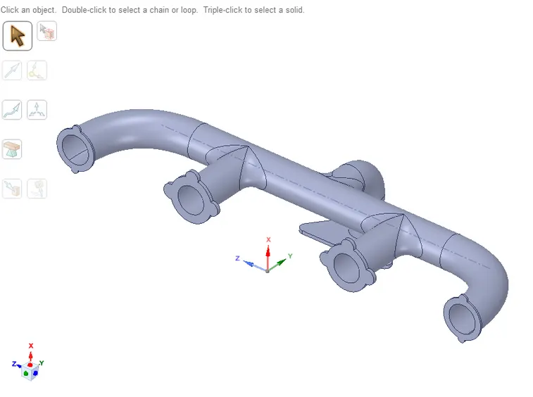
Geometry: first step is importing the geometry in to the space claim as shown below
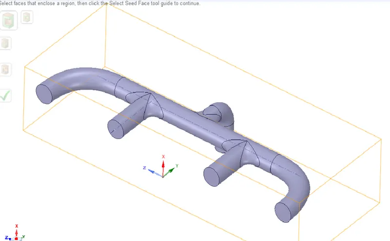
after importing the geometry we have to extract the fluid valume as shown below
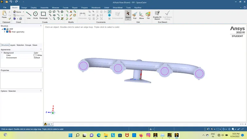
after extracting the fluid make sure that you have share the topology as shown below
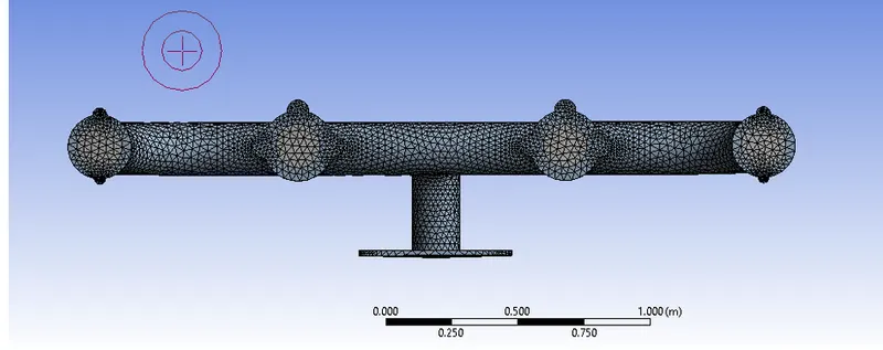
meshing: after successfull creation of geometry open mesh in ansys and construct the basic mess over it
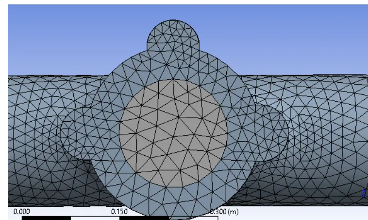
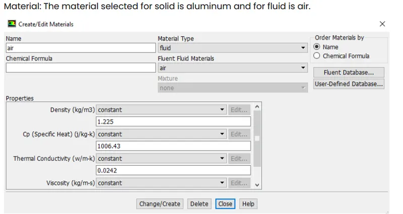
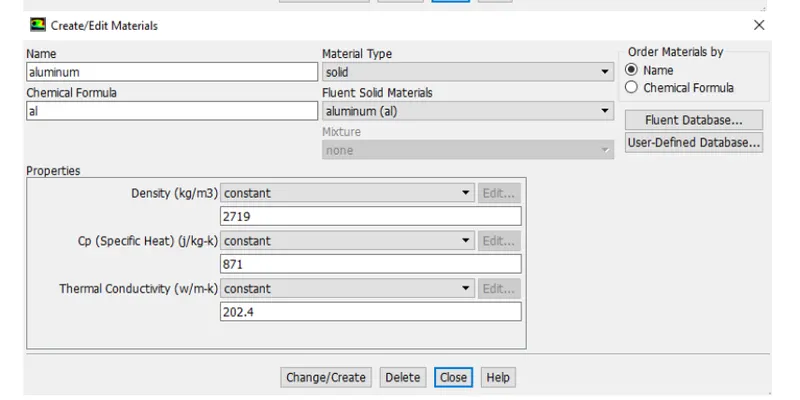
setup:after creating the mesh we have to set up the all the basiuc nassesary to run the simulation successfull as shown below
output:
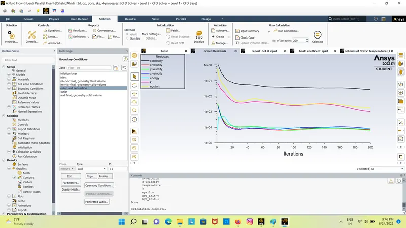
Residuals:
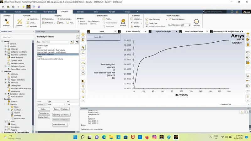
Heat transfer coefficent :
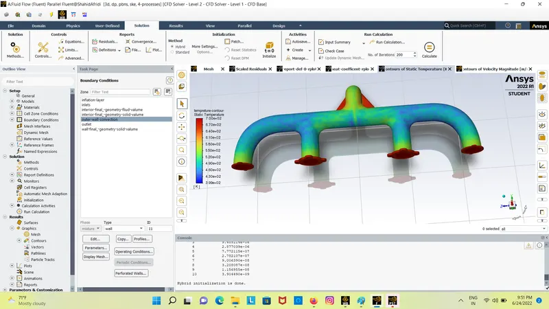
Tempreture:
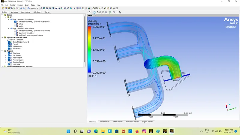
Streamline:
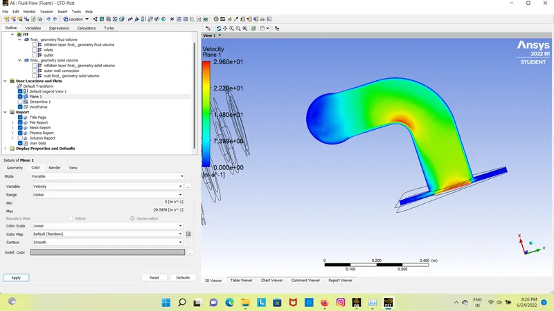
velocity plane:
tempreture plain:
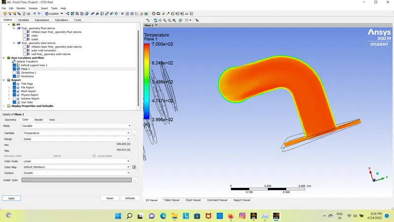
case 2: modifiying mesh to approprite y+
meshing: after successfull creation of geometry open mesh in ansys and construct the basic mess over it
- first we have construct meshing on exhoust port then we have to create the inflametion layer on fluid valume
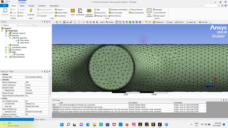
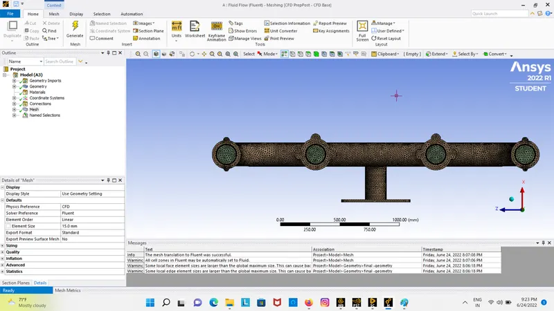
setup:after creating the mesh we have to set up the all the basiuc nassesary to run the simulation successfull as shown below
outputs
residuals:
heat transfer coefficent :
tempreture:
velocity plane:
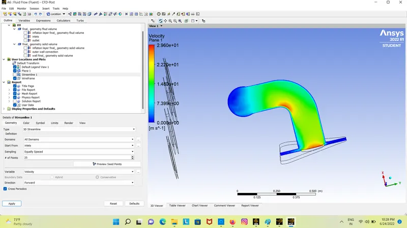
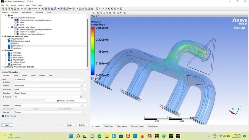
steamlines:
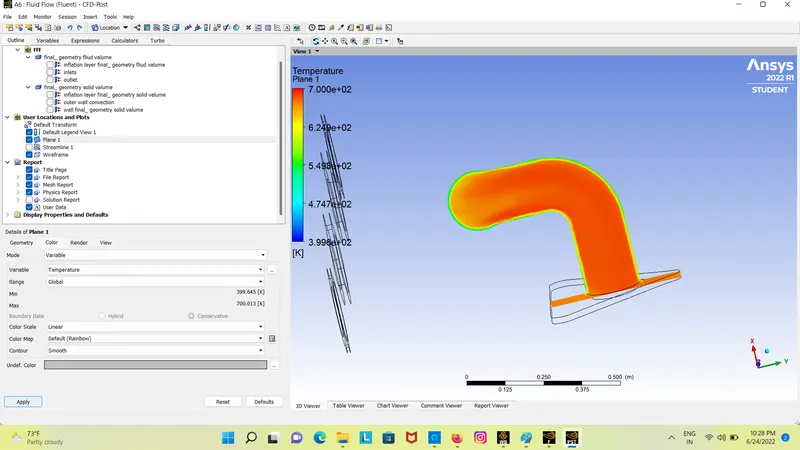
tempreture plane:
Facter that can be effect the result are :
- mesh quality
- Inflation layer on fluid valume
- properties of the meterial