Week 4 - CHT Analysis on Exhaust port
Aim:
CHT analysis of the exhaust port.
Objective:
- Give a brief description of why and where a CHT analysis is used.
- Maintain the y+ value according to the turbulence model and justify the results.
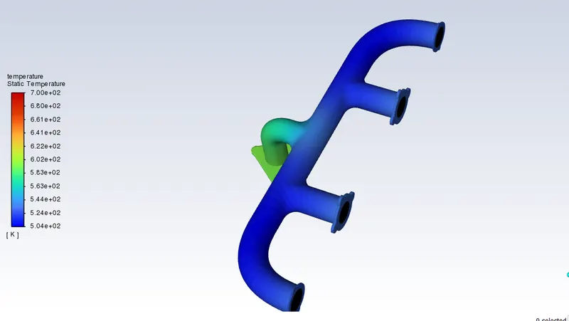
- Calculate the wall/surface heat transfer coefficient on the internal solid surface & show the velocity & temperature contours in appropriate areas.
- How would you verify if the HTC predictions from the simulations are right? On what factors does the accuracy of the prediction depend?
Procedure:
Creating the Geometry:
- Open the Ansys fluent and create a new model and import the model into the geometry.
- Opening the model in a geometric fluent workspace clearing and repairing all the extra parts that remain in the geometry. By using the Extra edges option.
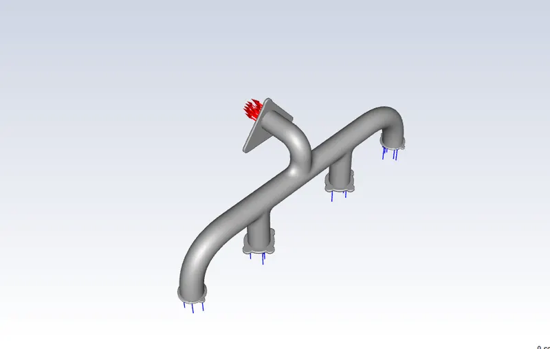
- Now as we have repaired the geometry then we can go to prepare option and select the individual inlet circles and make the model as a solid volume.
- After creating the solid volume we can go to the share option and click the share topology option which will share the topology of both the solid volume and the outer frame.
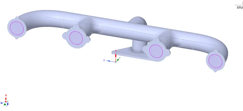
- A pink edge will be visible in the end after sharing which reminds us of the sharing edge. As u can see in the figure down.
- Now we are good to go to the Meshing.
Creating the Mesh:
- Opening the model in the fluent meshing model the model is automatically opened inside the fluent meshing.
- Now according to the meshing, we will generate mesh just to check if the model is meshing or not.
- After generating the meshing on the model. We can clear the model and again go to the meshing module.
- Go to the display and check the mesh size and give a size of 150mm.
- Select the faces of the inlet and outlet and give them the appropriate names of the inlet and outlet.
- Using the body selection we can select the outer frame and name it the outer walls.
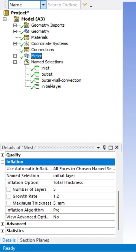
- Now going to the inflation selecting the inner solid volume using the body selection. And giving the name of the initial body layer.
- choosing the All the face-name selection and choosing the initial layer and giving the thickness.
- Now giving the maximum thickness to 5mm.
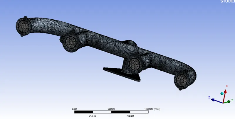
- Now generating the mesh
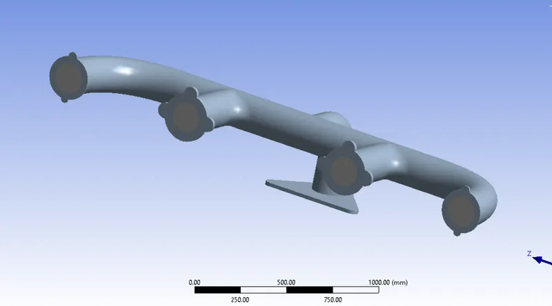
- Now after the generation of mesh is good and fine. As you can see below.
Creating the Setup:
- Opening the model in the setup module to initialize and run the iteration.
- As we opened the model we need to check for the meshing.
- After mesh check we have to provide the data to the flow like air, fluid, and solid, here we are taking the fluid.
- Now select the viscous model as K-epsilon.
- Going to boundaries and setting the inlet and outlet valves.
- Initialization using a Hybrid initializer.
- The making contour of temperature and velocity.
- Then create the animation and preview.
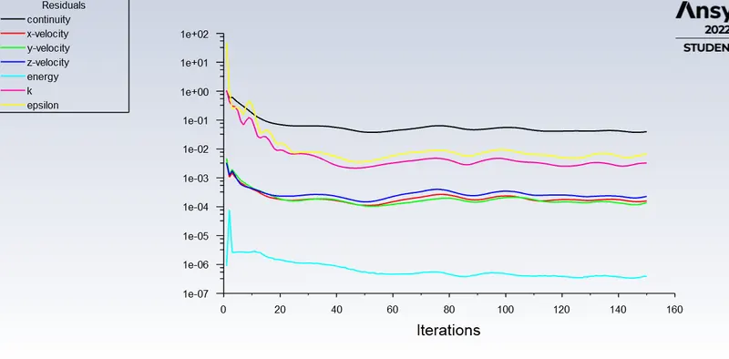
- Now going to iteration giving 150 times to iterate. And hit RUN.
Creating the Result:
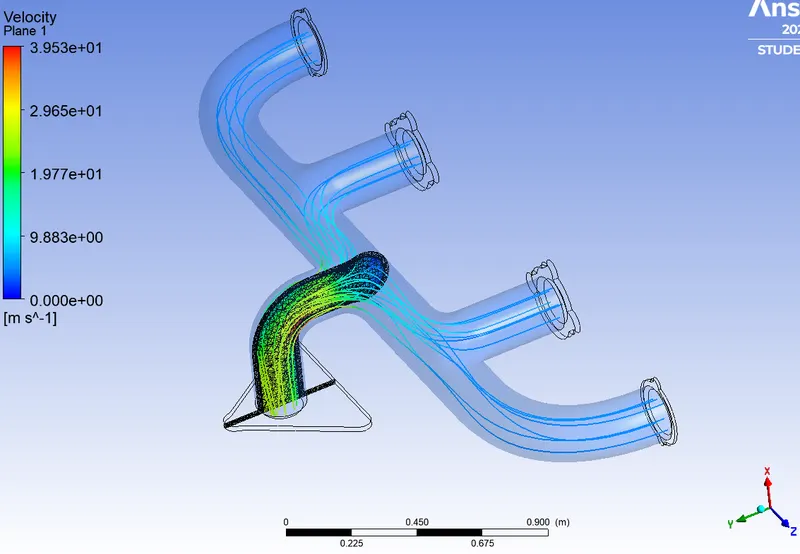
- Now Open the Result module to show the velocity of streamline flow.
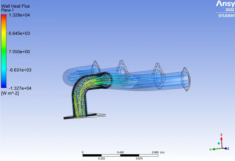
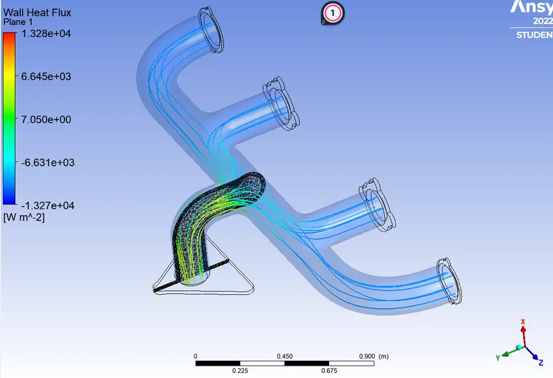
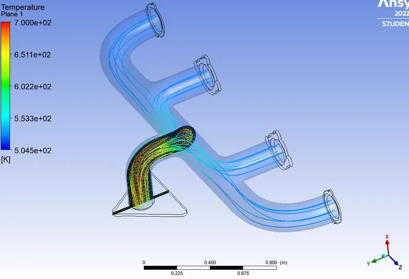
- inserting a plane XY in the middle of the outlet to demonstrate the streamlined temperature, velocity, and Wall heat convection.
- Now going to render and select the transparency to make the fluid visible.
- As you can see the wall heat flow below and velocity.
Conclusion:
Hence we have successfully done the CHT analysis flow.