Week 4 - CHT Analysis on Exhaust port
CHT ANALYSIS ON EXHAUST PORT
INTRODUCTION
Conjugate heat transfer (CHT) represents a class of multi-physics problems where fluidflow affects the thermal behaviour of structure, which inturn affects the fluid flow. For conjugate heat transfe analyses, the solid material conduction and the fluidconvection are analysed simultaneously. The conductiveheat transfer in a solid region is coupled to the convective heat transfer in a neighbouring fluid flow.
-The conjugate heat transfer become a more powerful tool for modeling and investigating nature phenomena and engineering system in different areas ranging from aerospace and nuclear reactors to thermal goods treatment and food processing from te complex procedure in medicines to oceans thermal interactin in metrology.
OBJECTIVES
- Import the exhaust port model in spaceclaim and extract volume for fluid flow.
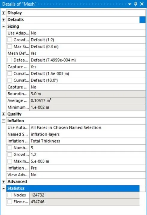
- Then we mesh the model with given size and suitable inflation layers.
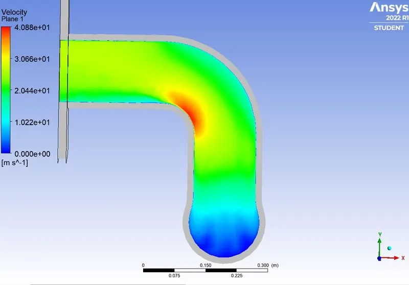
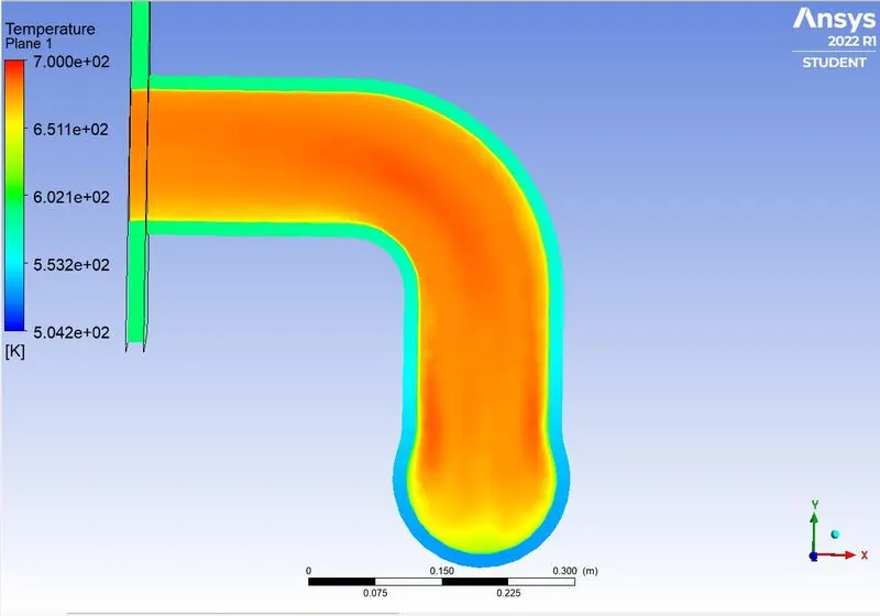
- Generate the velocity and temperature contour.
- Calculate the surface heat transfer coefficient on the internal solid surface.
PROCEDURE
In this project we are going to analysis heat interaction between exhaust and fluid flowing through it,for this we will use the mesh with different mesh sizing and coupled/simple method.
Pre-precessing
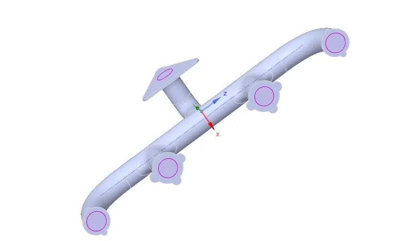
Geometry import into spaceclaim
Mesh generation
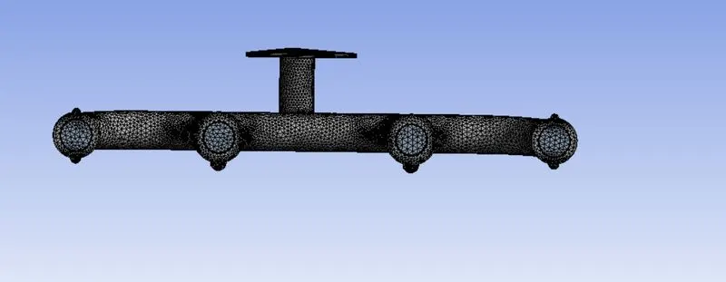
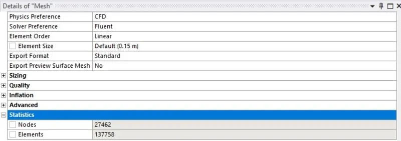
Mesh generation refers to the generation of nodal coordianates and element ,It is also includes the automatic numbering of nodes and elements based on a minimal amount of user supplied data .
The Mesh
For case1-
For case2-
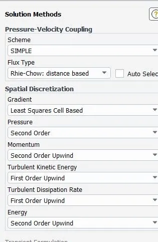
Solver setup in fluent
Boundary condition for flow analysis
All the values are fluid flow boundary condition isobtained from references. At inlet 5 m/s and temperature is
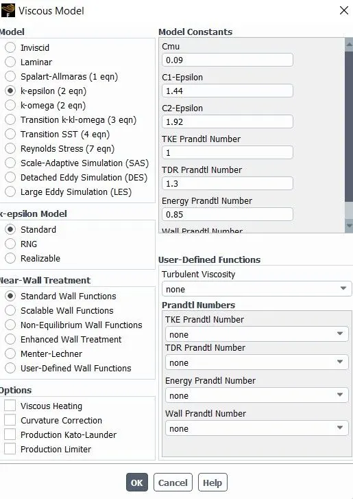
700K. that time exhaust gases are mixing like vorticity behavior and then static pressure is negligible. Wall condition is no slip wall means the viscous fluids states that at a solid boundary the fluid will have zero velocity relative to the boundary. Turbulence model is a turbulencemodelling is key issue in most CFD simulations.
Inlet bondary condition-
- velocity -5m/s
- Temperature-700k
Outlet boundary condition-
- pressure-0 gauge pressure (i.e 1 atmospric pressure)
Outer wall convection
- Heat transfer coefficient-20 `W/(m^2K)`
- Thermal condition - convection
Solver used
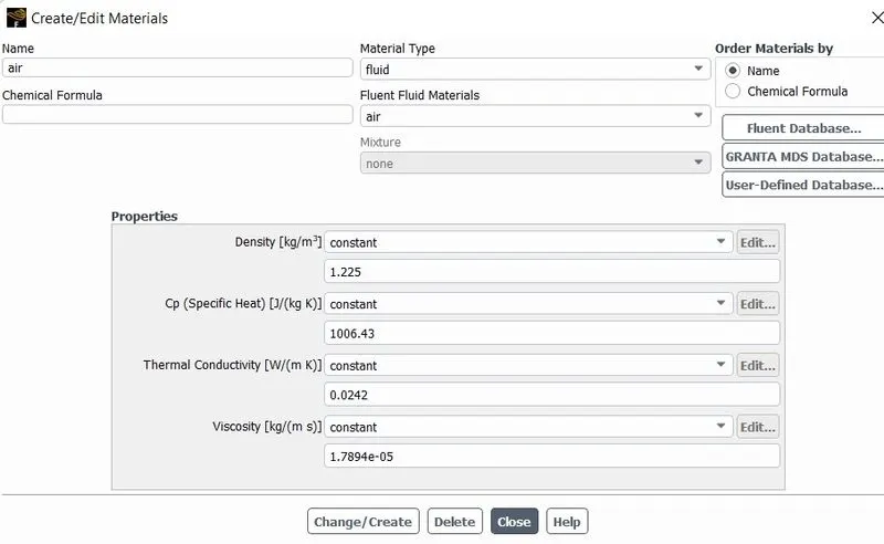
Material used
For Fluid
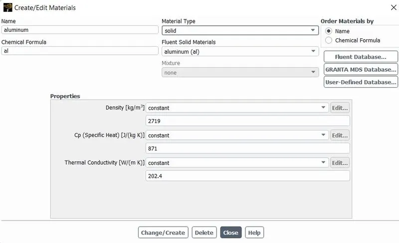
For solid
RESULTS
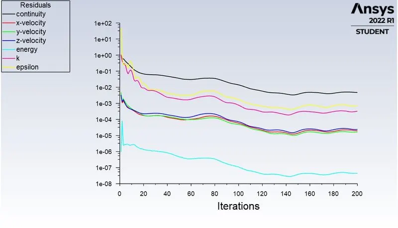
Case1-
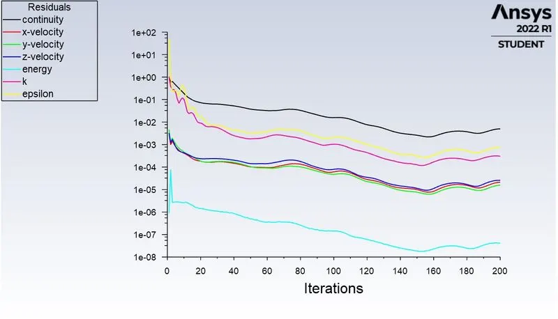
Residuals-
Velocity contour
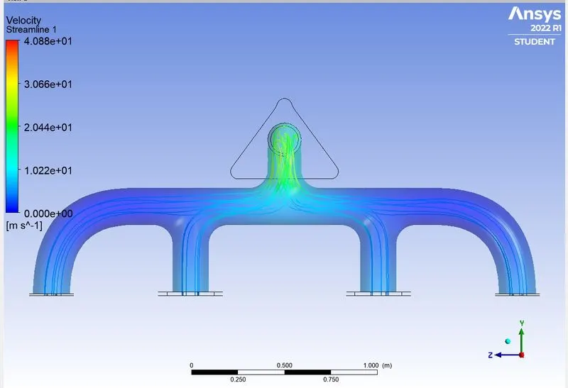
Stremline plot
Temperature contour
Case2(a)-
Residuals
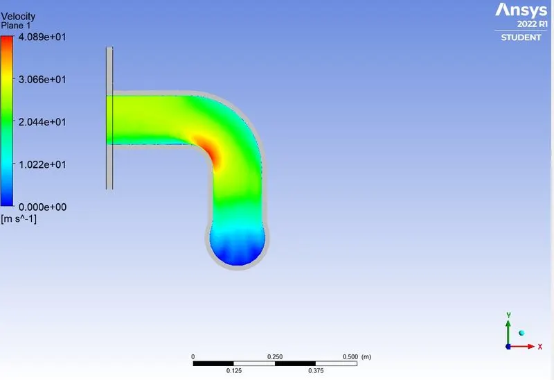
Velocity contour
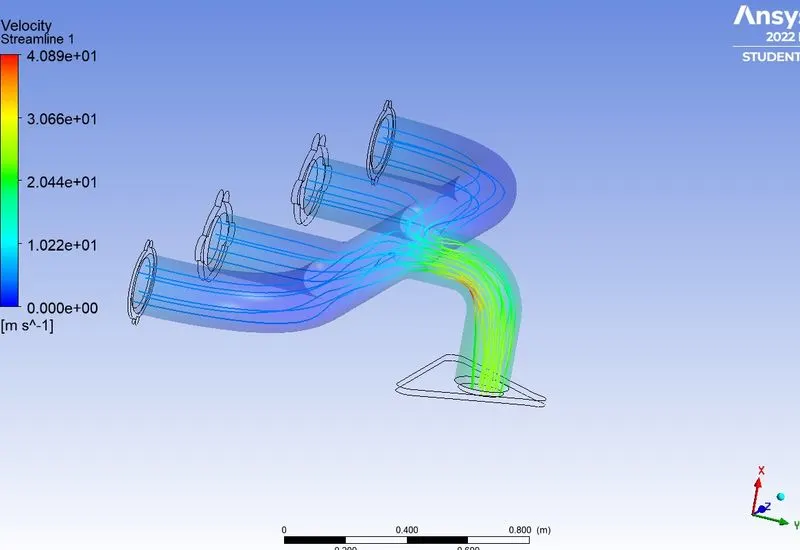
Stremline plot
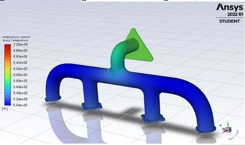
Temperature contour
Case2(b)- K-omega model
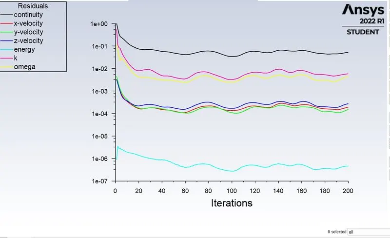
Residuals
Velocity contour
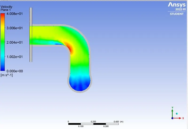
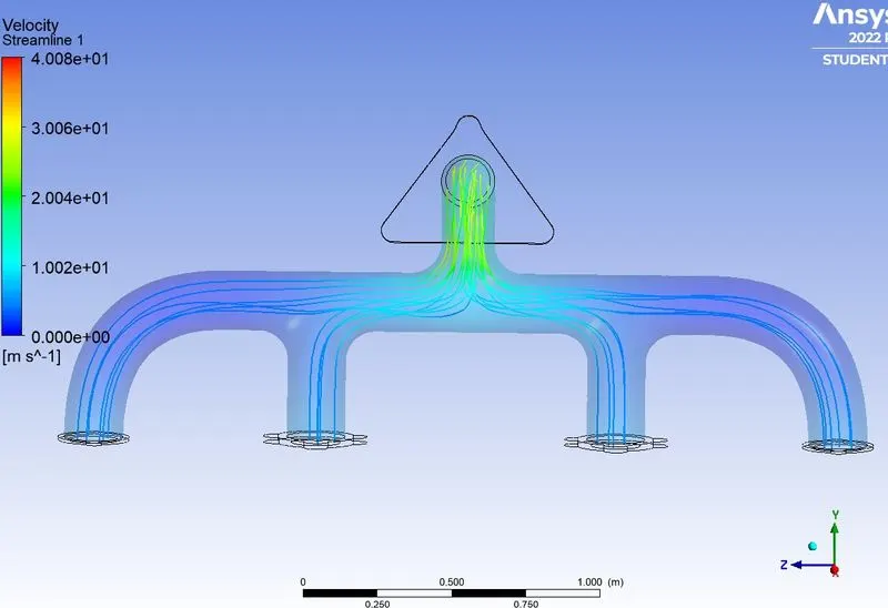
Stremline plot
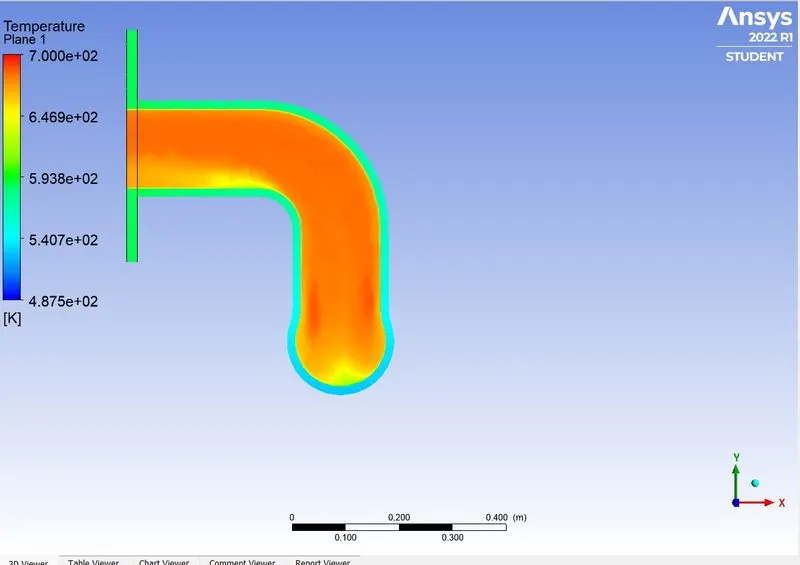
Temperature contour
Case 2(c)
With simple solver
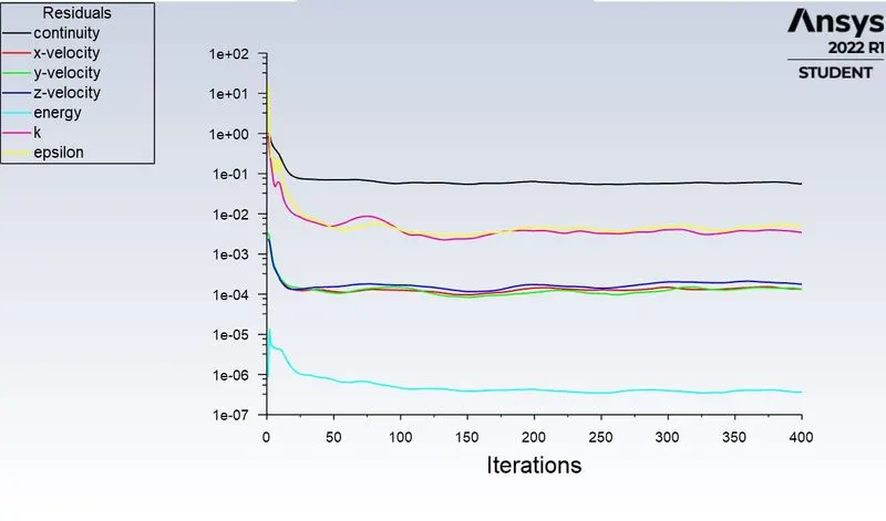
Residuals
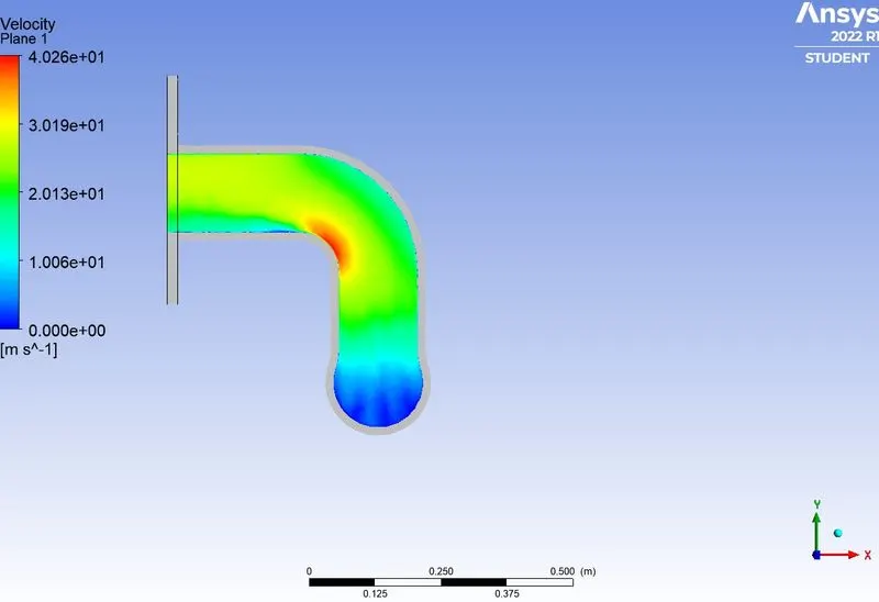
Velocity contour
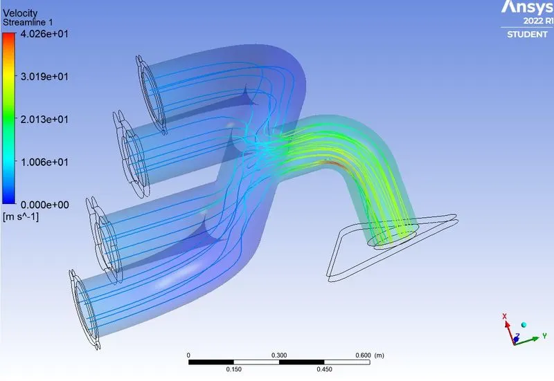
Stremline plot
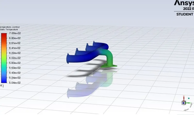
Temperature contour
COONCLUSION
The analysis on the exhaust port simulated succesfully and we conclude the CHT analysis has done to find out temperature rise mainfold because of hot air passing through it ans we predicted heat transfer coefficient as well .
Velocity contours were created to get insights of fluid path and maximum velocity area, it can be seen from graph that heat trasfer coefficient is related to wall only .Simulation is conductd in two different size mesh .The simulation can be performed for a wider range of base mesh size.
The accuracy of the heat transfer coefficient depends selecting the suitable value of Y+ and tubulance model .The heat transfer coefficient values predicted by cfd were valid aginst the numerical solution depicited the deviation ,which is in compliance with industrial standard.
DfjjgejfdufeiLDRRRddFKF