Week 4 - CHT Analysis on Exhaust port
Aim:
To carry out the Conjugate Heat Transfer (CHT) analysis of Exhaust Port.
Objectives:
Import of Exhaust-Port geometry to space-claim and then carry out a simulation on Ansys-Fluent to velocity and temperature distribution in the exhaust port. Below the following objective is to present in the report.
- Give a brief description of why and where a CHT analysis is used.
- Maintain the y+ value according to the turbulence model and justify the results.
- Calculate the wall/surface heat transfer coefficient on the internal solid surface & show the velocity & temperature contours in appropriate areas.
- How would you verify if the HTC predictions from the simulations are right? On what factors does the accuracy of the prediction depend on?
Model Preparation:
Import the geometry to the space claim (shown in Fig. 1). Then check for extra edges, if found removed it with the help of a tool named “Extra-Edges” from the toolbar.

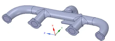
Figure 1. Exhaust port geometry.
To do Conjugate Heat Transfer (CHT), we need to define the fluid and solid domain. First, the fluid domain is separated from the geometry by using the tool command “volume extraction”. All the edges have been selected and then the volume is extracted. The extracted fluid volume is shown in Fig. 2. The solid volume is shown in Fig. 3. The fluid and solid domain are two separate entities and are combined together as a single component named “Final Geometry”.
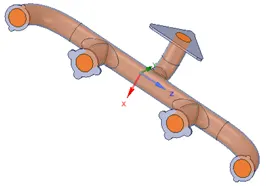
Figure 2. Fluid domain
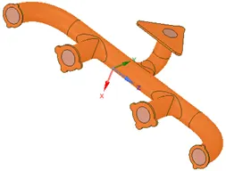
Figure 3. Solid domain
For CHT, an interface is required between the solid domain and the fluid domain. “Share” tool command is needed to share the solid and fluid domain to share the heat transfer phenomena by creating an interface between them, as shown in Fig. 4.
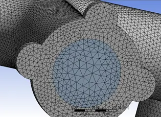
Figure 4. Interface creation between solid and fluid domain.
Meshing:
The inflation layers are created by maintaining the y+ value. The maximum thickness is kept 5 mm with a number of layer 5 and a growth rate of 1.2 (shown in Fig. 5).
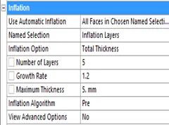

Figure 5. Inflation layer
In the Final mesh number of elements are 47,4846.
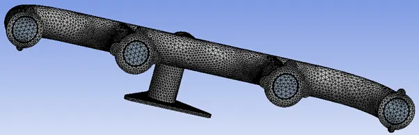
Figure 6. Final Mesh
Simulation details:
A steady-state simulation is carried out using Pressure based solver. For turbulence, k-epsilon turbulence model parameters (k-ε model.) has been used. A No-slip boundary condition is used on the walls. For the near-wall treatment, a standard wall function has been used. Inlet flow velocity normal to boundary condition is taken as 5 m/s with an inlet temperature of 700 K for the simulation. For convection, in the outer wall heat transfer coefficient is kept at 20 w/m2K. Aluminium and Air are used as materials. Hybrid initialization has been done for simulation.
Objectives:
- Give a brief description of why and where a CHT analysis is used.
The conjugate heat transfer (CHT) is a type of thermal interaction of conduction within the solid and convection between the solid surface to the fluid flowing over or through it. Aerospace, nuclear engineering, biology, cooling of electronic chips, and meteorology etc. are typical examples of CHT. It is mainly used when there is heat transfer occurs from solid to fluid or vice versa.
- Maintain the y+ value according to the turbulence model and justify the results.
The total thickness of the inflation layer is 5 mm. y+ helps in understanding how coarse or fine mesh is near the wall. The value of y+ should be less than 10 for viscous sublayer and for turbulence modelling its value is more than 30.
Calculation of y+,  Where y= distance from wall,
  = friction velocity (m/s), defined as velocity near the wall, and = Kinematic viscosity (kg/m-s)
To calculate friction velocity
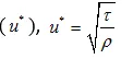
 Wall Shear stress=
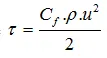
 = Skin friction coefficient.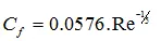
Where, Reynold number (Re) is defined as

To calculate Reynolds number=


Skin friction coefficient,

Wall Shear stress=

friction velocity, m/s


Since 20% of growth is given to the inflation layer. Distance from the wall (i.e., y) is 0.63 mm, and the layer growth rate is 1.2.
|
Layer |
Value (mm) |
|
1st layer |
1.26 |
|
2nd layer |
1.512 |
|
3rd layer |
1.8144 |
|
4th layer |
2.1772 |
|
5th layer |
2.6127 |
|
Total thickness |
9.3763 |
The total thickness of 5 mm considered in the simulation is less than the allowable thickness i.e., 9.3763 mm. Hence, considered inflation layer thickness justifies the turbulence model considered in the simulation.
- Calculate the wall/surface heat transfer coefficient on the internal solid surface & show the velocity & temperature contours in appropriate areas.
Wall heat transfer coefficient calculation:
Heat transfer coefficient can be calculated from Nusselt number (Nu)
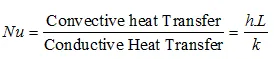
Where, h= convective heat transfer coefficient (W/m2K)
L= Characteristic length= 0.17 m
k= Thermal conductivity= 0.0242 W/mK
Nusselt number from Dittus-Boelter equation=

Reynolds no. (Re)= 58497.2 and Prandtl no. (Pr) of air at 700 K =0.71
Now,


Hence h=18.6 W/m2K
Velocity Contour
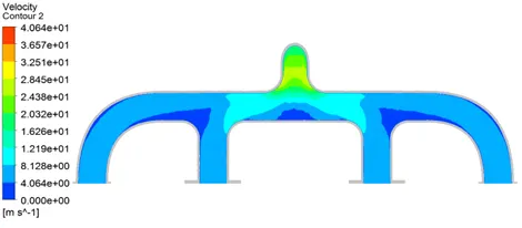
Figure 7. Velocity at YZ plane
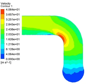
Figure 8. Velocity at Z=0 m plane
Temperature Contour
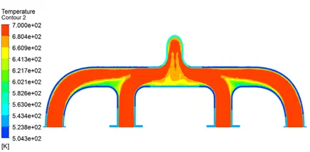
Figure 9. The temperature at the YZ plane
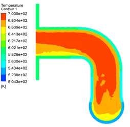
Figure 10. The temperature at Z=0 m plane
Wall Heat Transfer Coefficient Contour

Figure 11. Wall Heat Transfer at Z=0 m plane
- How would you verify if the HTC predictions from the simulations are right? On what factors does the accuracy of the prediction depend on?
HTC prediction i.e. is equal to 20 W/m2K which nearly equals to the calculated value of h=18.6 W/m2K (from equation 1). Hence, it shows predicted value is right. The discrepancy is may be due to the consideration of the roughness of the pipe of exhaust pipe.
Conclusions:
- Velocity tends to increase from inlet to outlet, due to mass conservation.
- Heat transfer coefficient is high at outlet area, due to high velocity which also shows high heat transfer from the fluid to solid.
- The amount of heat transfer depends on velocity, i.e., high velocity means higher Reynolds number which contributes to more heat transfer.