Week 3 - External flow simulation over an Ahmed body.
Aim: Define Ahmed's body and its importance, perform a grid independence test, explain the reason for the negative pressure in the wake region and the significance of the point of separation.
Ahmed Body
With advancements in computational techniques and higher-order analytical models, predicting the stability behaviour and aerodynamic response becomes more precise. Hence, an Ahmed body is developed by TU Delft University a simple shape with basic aerodynamic properties of a vehicle, which has been used to know the flow region, drag/lift values, flow separation, stability and wake zone of a car through the simulation instead of doing the number of experiments. Data obtained by Ahmed body simulation is used for validation.
Mesh

Fig 1. Mesh statistic for 335064 elements

Fig 2. Mesh statistic for 608372 elements
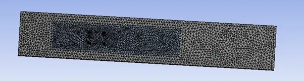
Fig 3. Meshing for 608372 elements
For the Inflation layer to take care of turbulence, the first layer height 1 mm, the maximum layer is taken as 5 with a growth rate of 1.2 is given Car.
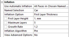
Fig 4. Inflation layer Mesh for 608372 elements
Grid Independence Study
In the present study, an Ahmed body meshing and simulation have been done in Ansys V. 19 to investigate the effect of fluid velocity over it. Grid independent, as shown in Fig. 5, a test has been done to ensure the reliability of obtained results and to read small property variations. A total of 60,8372 numbers of elements as a grid-independent element is found.
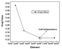
Fig 5. Grid Independence study
Simulation detail:
The governing equations for mass, momentum and energy are solved employing the CFD code. A density-based solver has been used to do the 3-D Ahmed body steady-state simulation. In the solution method, an implicit method formulation along with the Roe-FDS flux type has been implemented. For turbulence, Standard k-epsilon turbulence model parameters (k-ε model.) has been used. The reason for the k-ε model is to ensure the precise analysis near and away from the wall to capture accurate streamline and wake region information. A No-slip boundary condition is used on the walls. For the near-wall treatment, a standard wall function has been assumed in case of turbulent flow. The flow and turbulence governing equations are iterated with a second-order upwind scheme. Flow velocity is taken as 25 m/s for the simulation.
Material Specification
|
Density (kg/m3) |
Specific heat (j/kg-K) |
Thermal cond. (W/m-K) |
Viscosity (kg/m-s) |
|
|
Air |
1.225 |
1006.43 |
0.0242 |
1.7894e-05 |
|
Ahmed Body |
2719 |
871 |
202.4 |
N.A. |
Results and Discussion
- Pressure and Velocity Contours
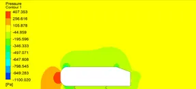
Fig 6: Pressure contour
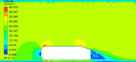
Fig 7: Velocity contour
- Drag coefficient plot for refine mesh
Figure 7 depicts the drag coefficient plot for the refine mesh having 60,8372 elements. The value of the drag coefficient is 0.33.
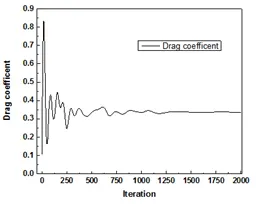
Fig 7: Drag coefficient plot for refine the mesh.
- Wake region vector plot
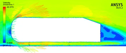
Fig 8: Velocity streamline with wake region
When the fluid flows over the body and gets separated at the rear end, it creates a low-pressure region behind the body known as the wake region. This wake increases the chance of the formation of pressure drag, which ultimately reduces the vehicle performance. The wake is low-pressure because fluid gets separated at higher Reynolds numbers and increases the drag magnitude. The negative pressure gradient in the wake region depends on the pressure gradient and the vortex shedding in the rear part of the body. The magnitude of pressure will increase if we move away from the wake region.
- Significance of the point of separation
The separation point is when the fluid flows over a body stop "sticking" on the surface of the body. Till fluid flow around the object sticks to the object, forms a boundary layer. This "attached flow" is flowing very smoothly. The positive pressure gradient is responsible for boundary layer separation. When separation of flow occurs, the turbulent flow behind the body decreases in pressure, causing an increase in pressure drag. We can prevent the point of separation by Streamlining the body shape.
Conclusions
- The increase in drag was attributed to the change in the near-wake structure.
- An asymmetric flow structure was found around the Ahmed body and resulted in a surface pressure distribution.
- Slant angle plays a major role, especially for the magnitude of drag force.