Week 4 Challenge- Shear Forces, Bending Moments and Stiffness/Flexibility Matrix
Objective:- To solve the given questions and develop a Matlab module wherever required
Solution Procedure: -
1) Assume a cantilever beam. Develop flexibility matrix for the same
From the differential equation for the elastic curve`
(d^ 2 v)/(d^2 x) = (Mz)/ (EI z) = 1/( EIz)* [F y 2(L - x) + Mz2]`
Integrating
`(d v)/(d x) = 1/( EIz)* [F y 2(Lx - x^2/2) + Mz2] + C1`
and
`v = 1/( EIz)* [F y 2(Lx ^2/2- x^3/6) + Mz2] + C1x+C2`
Applying the boundary conditions
`(d v)/(d x) = 0
at x = 0
therefore C1 = 0 and v= 0 (at x =0)
therefore C2 = 0
Elastic curve equations:
`v = 1/( EIz)* [F y 2(Lx ^2/2- x^3/6) + Mz2x^2]`
``(d v)/(d x) = (Fy*x)/(EIz)[L -x/2] + Mz2 * x/EIz`
the Flexibility influence coefficients
v2 =v(at x = L)
`(FyL^3)/(3EIz) + (Mz2*L^2)/(2EIz)`
theta = `(Fy*L^2)/(2EIz) +( Mz2*L)/(EIz)`
Assemble equation in matrix form
`{v2 , theta}`= `L/(EIz)``[L^2/3` `L/2` `{Fy ,Mz2}`
`L/2` `1]`
_______________________________________________________________________________________________________________
2) Use the equations developed in problem 1 and write a Matlab module to calculate coefficients in a flexibility matrix for a cantilever beam
Code for the above problem: -
Explanation of the above code: -
function[cantilever]= cantilever_beam(node_xy,elements,E,b,h,fy)

    %Number of elements
    no_elements = size(elements,1);
    %Crosee section area
    A= b*h;
    %moment of inertia
    I =b*h^3/12;
    node_x =node_xy(:,1);
    node_y = node_xy(:,2);

    x_co = node_x(2,1) - node_x(1,1);
    y_co = node_y(2,1) - node_y(1,1);


    L= sqrt(x_co*x_co + y_co*y_co);
    Mz2 = L*fy

    %Step 1:flexibility matrix

    v2 = [(fy*(L^3))/(3*E*I)+ (Mz2*L^2)/(2*E*I)]
    theta = [(fy*(L^2))/(2*E*I)+ (Mz2*L^2)/(2*E*I)]
end
function[cantilever]= cantilever_beam(node_xy,elements,E,b,h,fy) - function to develop a cantileer beam flexibility matrix coefficients
%Number of elements
no_elements = size(elements,1); - to calculate the number of elements
%Crosee section area
A= b*h; - to calculate cross-section area of the beam
%moment of inertia
I =b*h^3/12; - to calculate the moment of intertia of the beam
node_x =node_xy(:,1);
node_y = node_xy(:,2);
x_co = node_x(2,1) - node_x(1,1);
y_co = node_y(2,1) - node_y(1,1);
L= sqrt(x_co*x_co + y_co*y_co); to calculate the length of the beam
Mz2 = L*fy - to calculate the moment generated
%Step 1:flexibility matrix
v2 = [(fy*(L^3))/(3*E*I)+ (Mz2*L^2)/(2*E*I)] - coefficientsfor the flexibility matrix
theta = [(fy*(L^2))/(2*E*I)+ (Mz2*L^2)/(2*E*I)] - coefficientsfor the flexibility matrix
end - end of the function
_______________________________________________________________________________________________________________
3) Using the Matlab module developed in Problem 2 solve the following beam problem Calculate the Bending Moment and Shear force diagram
a) For the cantilever beam subjected to uniformly distributed load as shown below compute the displacement and rotation at end B
function[cantilever]= cantilever_beam(node_xy,elements,E,b,h,fy)

    %Number of elements
    no_elements = size(elements,1);
    %Crosee section area
    A= b*h;
    %moment of inertia
    I =b*h^3/12;
    node_x =node_xy(:,1);
    node_y = node_xy(:,2);

    x_co = node_x(2,1) - node_x(1,1);
    y_co = node_y(2,1) - node_y(1,1);


    L= sqrt(x_co*x_co + y_co*y_co)
    Mz2 = L*fy

    %Step 1:flexibility matrix coefficients


    v2 = [(fy*(L^3))/(3*E*I)+ (Mz2*L^2)/(2*E*I)]
    theta = [(fy*(L^2))/(2*E*I)+ (Mz2*L^2)/(2*E*I)]
end
Calculate the Bending Moment and shear force diagram
% This Matlab code can be used for simply supported beam with single point
% load or uniformly distributed to find the
% * Support reaction
% * Maximum Bending Moment
% * Shear force diagram
% * Bending Moment daigram
clc;
clear all;
close all;
disp('Simply Supported Beam');
% Data input section
disp(' ');
L    = input('Length of beam in meter =  ');
disp(' ');disp('Type 1 for point load, Type 2 for udl')
Type = input('Load case = ');
if Type == 1
disp(' ');
W = input('Load applied in kN = ');
disp(' ');
p = input('Location of Load from left end of the beam in meter = ');
c  = L-p;
R1 = W*(L-p)/L;             % Left Support Reaction.
R2 = W*p/L;                 % Right Support Reaction.
else
    disp(' ');
    W  = input('Uniformly distributed load in kN/m = ');
    disp(' ');
    b  = input('Length of udl in meter = ');
    disp(' ');
    cg = input('C.G of udl from left end of the beam in meter = ');
    p  = (cg-b/2);
    c  = L-p-b;

    R1 = W*b*(b+2*c)/(2*L); % Left Support Reaction.
    R2 = W*b*(b+2*p)/(2*L);                 % Right Support Reaction.
end

% Discretization of x axis.
n = 1000;                   % Number of discretization of x axis.
delta_x = L/n;              % Increment for discretization of x axis.
x = (0:delta_x:L)';         % Generate column array for x-axis.
V = zeros(size(x, 1), 1);   % Shear force function of x.
M = zeros(size(x, 1), 1);   % Bending moment function of x.
% Data processing section
if Type == 1
for p = 1:n+1
    % First portion of the beam, 0 < x < b
    V(p) = R1;
    M(p) = R1*x(p);

    % Second portion of the beam, b < x < L
    if x(p) >= p
        V(p) = R1-W;
        M(p) = R1*x(p)-W*(x(p)-p);
    end
end
x1   = p;
Mmax = W*p*(L-p)/L;
else
   for p = 1:n+1
    % First portion of the beam, 0 < x < a
    if x(p) < p
    V(p) = R1;
    M(p) = R1*x(p);
    elseif p <= x(p) && x(p)< p+b
    % Second portion of the beam, a < x < a+b
        V(p) = R1-W*(x(p)-p);
        M(p) = R1*x(p)-W*((x(p)-p)^2)/2;
    elseif x(p) >= (p+b)
    % Second portion of the beam, a+b < x < L
        V(p) = -R2;
        M(p) = R2*(L-x(p));
    end
   end
   x1 = p+b*(b+2*c)/(2*L);
   Mmax = W*b*(b+2*c)*(4*p*L+2*b*c+b^2)/(8*L^2);
end
disp(' ');disp (['Left support Reaction'  '  = ' num2str(R1) ' ' 'kN'])
disp(' ');disp (['Left support Reaction'  '  = ' num2str(R2) ' ' 'kN'])
disp(' ');disp (['Maximum bending moment'  ' = ' num2str(Mmax) ' ' 'kNm'])
figure
subplot(2,1,1);
plot(x, V, 'r','linewidth',1.5);
grid
line([x(1) x(end)],[0 0],'Color','k');
line([0 0],[0 V(1)],'Color','r','linewidth',1.5);
line([x(end) x(end)],[0 V(end)],'Color','r','linewidth',1.5);
title('Shear Force Diagram','fontsize',16)
text(p/2,V(1),num2str(V(1)),'HorizontalAlignment','center','FontWeight','bold','fontsize',16)
text((L-c/2),V(end),num2str(V(end)),'HorizontalAlignment','center','FontWeight','bold','fontsize',16)
axis off
subplot(2,1,2);
plot(x, M, 'r','linewidth',1.5);
grid
line([x(1) x(end)],[0 0],'Color','k');
line([x1 x1],[0 Mmax],'LineStyle','--','Color','b');
title('Bending Moment Diagram','fontsize',16)
text(x1+1/L,Mmax/2,num2str(roundn(Mmax,-2)),'HorizontalAlignment','center','FontWeight','bold','fontsize',16)
text(x1,0,[num2str(roundn(x1,-2)) ' m'],'HorizontalAlignment','center','FontWeight','bold','fontsize',16)
axis off
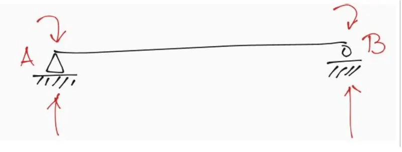
4) Assume a simply supported beam Develop stiffness matrix for the same using slope-deflection equations
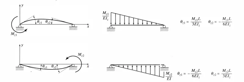
`thetaz1 = (Mz1L)/(3EIz)` `thetaz1 = -(Mz2L)/(6EIz)``
`thetaz2 = -(Mz1L)/(6EIz)`` `thetaz2 = (Mz2L)/(3EIz)``
Flexible matrix for the above question

Using the slope deflection equation
`Mz1 = (EIz)/L*(4thetaz1 +2thetaz2 - (6delta)/L)`
`Mz2= (EIz)/L*(2thetaz1 +4thetaz2 - (6delta)/L)`
Let `delta = v2 -v1`
`Mz2= (EIz)/L*(4thetaz1 +2thetaz2 +(6v1)/L -(6v2)/L )`
`Mz1= (EIz)/L*(4thetaz1 +2thetaz2 +(6v1)/L -(6v2)/L )`
By equilibrium equation
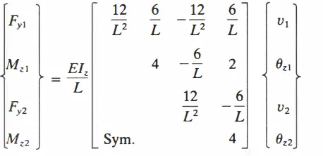
`Fy1 = (Mz1+Mz2)/L = (EIz)/L*(6thetaz1 +6thetaz2 +(12v1)/L^2 -(12v2)/L^2 )`
`Fy2 = -(Mz1+Mz2)/L = (EIz)/L*(-6thetaz1 -6thetaz2 -(12v1)/L^2 +(12v2)/L^2 )`
Stiffness Matrix generated
_______________________________________________________________________________________________________________
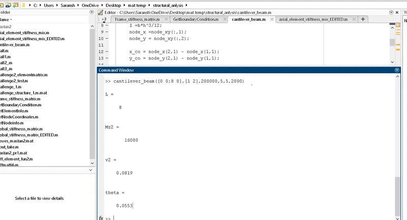
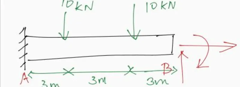
3 b) For the cantilevers subjected to point loads as shown below compute the displacement and rotation at end B
function[cantilever]= cantilever_beam(node_xy,elements,E,b,h,fy)

    %Number of elements
    no_elements = size(elements,1);
    %Crosee section area
    A= b*h;
    %moment of inertia
    I =b*h^3/12;
    node_x =node_xy(:,1);
    node_y = node_xy(:,2);

    x_co = node_x(2,1) - node_x(1,1);
    y_co = node_y(2,1) - node_y(1,1);


    L= sqrt(x_co*x_co + y_co*y_co)
    Mz2 = L*fy

    %Step 1:flexibility matrix coefficients


    v2 = [(fy*(L^3))/(3*E*I)+ (Mz2*L^2)/(2*E*I)]
    theta = [(fy*(L^2))/(2*E*I)+ (Mz2*L^2)/(2*E*I)]
end
Explanation of the above code:-
function[cantilever]= cantilever_beam(node_xy,elements,E,b,h,fy) - function to develop a cantileer beam flexibility matrix coefficients
%Number of elements
no_elements = size(elements,1); - to calculate the number of elements
%Crosee section area
A= b*h; - to calculate cross-section area of the beam
%moment of inertia
I =b*h^3/12; - to calculate the moment of intertia of the beam
node_x =node_xy(:,1);
node_y = node_xy(:,2);
x_co = node_x(2,1) - node_x(1,1);
y_co = node_y(2,1) - node_y(1,1);
L= sqrt(x_co*x_co + y_co*y_co); to calculate the length of the beam
Mz2 = L*fy - to calculate the moment generated
%Step 1:flexibility matrix
v2 = [(fy*(L^3))/(3*E*I)+ (Mz2*L^2)/(2*E*I)] - coefficientsfor the flexibility matrix
theta = [(fy*(L^2))/(2*E*I)+ (Mz2*L^2)/(2*E*I)] - coefficientsfor the flexibility matrix
end - end of the function
______________________________________________________________________________________________________________
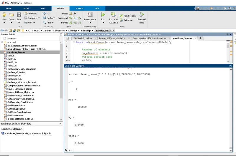
The output of the above code for the problem:-
_______________________________________________________________________________________________________________
5) Using equations developed in problem 4 develop a Matlab module to calculate coefficients in a stiffness matrix for simply supported beam
function[k_element] = Frame_Stiffness_Matrix1(node_xy,A,I,length_element)
%Step 1: To construct element stiffness matrix
E =2*10^11;
frame_stiffness=zeros(6,6);
 k11 =A*E/length_element;
    k22 =12*E*I/length_element^3;

    k23= 6*E*I/length_element^2;
    k33 = 4*E*I/length_element;

    k36 = 2*E*I/length_element;

    frame_stiffness(:,:) = [k11 0 0 -k11 0 0;0 k22 k23 0 -k22 k23;0 k23 k33 0 -k23 k36;-k11 0 0 k11 0 0;0 -k22 -k23 0 k22 -k23;0 k23 k36 0 -k23 -k33]
_______________________________________________________________________________________________________________
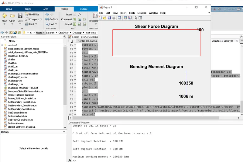
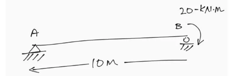
6) Using the Matlab module developed in problem 5 solve the following beam problem Calculate bending moment and shear force diagram
% This Matlab code can be used for simply supported beam with single point
% load or uniformly distributed to find the
% * Support reaction
% * Maximum Bending Moment
% * Shear force diagram
% * Bending Moment daigram
clc;
clear all;
close all;
disp('Simply Supported Beam');
% Data input section
disp(' ');
L    = input('Length of beam in meter =  ');
disp(' ');disp('Type 1 for point load, Type 2 for udl')
Type = input('Load case = ');
if Type == 1
disp(' ');
W = input('Load applied in kN = ');
disp(' ');
p = input('Location of Load from left end of the beam in meter = ');
c  = L-p;
R1 = W*(L-p)/L;             % Left Support Reaction.
R2 = W*p/L;                 % Right Support Reaction.
else
    disp(' ');
    W  = input('Uniformly distributed load in kN/m = ');
    disp(' ');
    b  = input('Length of udl in meter = ');
    disp(' ');
    cg = input('C.G of udl from left end of the beam in meter = ');
    p  = (cg-b/2);
    c  = L-p-b;

    R1 = W*b*(b+2*c)/(2*L); % Left Support Reaction.
    R2 = W*b*(b+2*p)/(2*L);                 % Right Support Reaction.
end

% Discretization of x axis.
n = 1000;                   % Number of discretization of x axis.
delta_x = L/n;              % Increment for discretization of x axis.
x = (0:delta_x:L)';         % Generate column array for x-axis.
V = zeros(size(x, 1), 1);   % Shear force function of x.
M = zeros(size(x, 1), 1);   % Bending moment function of x.
% Data processing section
if Type == 1
for p = 1:n+1
    % First portion of the beam, 0 < x < b
    V(p) = R1;
    M(p) = R1*x(p);

    % Second portion of the beam, b < x < L
    if x(p) >= p
        V(p) = R1-W;
        M(p) = R1*x(p)-W*(x(p)-p);
    end
end
x1   = p;
Mmax = W*p*(L-p)/L;
else
   for p = 1:n+1
    % First portion of the beam, 0 < x < a
    if x(p) < p
    V(p) = R1;
    M(p) = R1*x(p);
    elseif p <= x(p) && x(p)< p+b
    % Second portion of the beam, a < x < a+b
        V(p) = R1-W*(x(p)-p);
        M(p) = R1*x(p)-W*((x(p)-p)^2)/2;
    elseif x(p) >= (p+b)
    % Second portion of the beam, a+b < x < L
        V(p) = -R2;
        M(p) = R2*(L-x(p));
    end
   end
   x1 = p+b*(b+2*c)/(2*L);
   Mmax = W*b*(b+2*c)*(4*p*L+2*b*c+b^2)/(8*L^2);
end
disp(' ');disp (['Left support Reaction'  '  = ' num2str(R1) ' ' 'kN'])
disp(' ');disp (['Left support Reaction'  '  = ' num2str(R2) ' ' 'kN'])
disp(' ');disp (['Maximum bending moment'  ' = ' num2str(Mmax) ' ' 'kNm'])
figure
subplot(2,1,1);
plot(x, V, 'r','linewidth',1.5);
grid
line([x(1) x(end)],[0 0],'Color','k');
line([0 0],[0 V(1)],'Color','r','linewidth',1.5);
line([x(end) x(end)],[0 V(end)],'Color','r','linewidth',1.5);
title('Shear Force Diagram','fontsize',16)
text(p/2,V(1),num2str(V(1)),'HorizontalAlignment','center','FontWeight','bold','fontsize',16)
text((L-c/2),V(end),num2str(V(end)),'HorizontalAlignment','center','FontWeight','bold','fontsize',16)
axis off
subplot(2,1,2);
plot(x, M, 'r','linewidth',1.5);
grid
line([x(1) x(end)],[0 0],'Color','k');
line([x1 x1],[0 Mmax],'LineStyle','--','Color','b');
title('Bending Moment Diagram','fontsize',16)
text(x1+1/L,Mmax/2,num2str(roundn(Mmax,-2)),'HorizontalAlignment','center','FontWeight','bold','fontsize',16)
text(x1,0,[num2str(roundn(x1,-2)) ' m'],'HorizontalAlignment','center','FontWeight','bold','fontsize',16)
axis off
Output of above code:-