Week 4 Challenge : CFD Meshing for BMW car
Objective:-
To clean up the given car model and perform surface meshing for the given mesh lengths and create a wind tunnel around the car with surface mesh and volumetric mesh for volume in the tunnel surrounding the car.
PROCEDURE :-
- The first step is to import the geometry and run a geometry check.
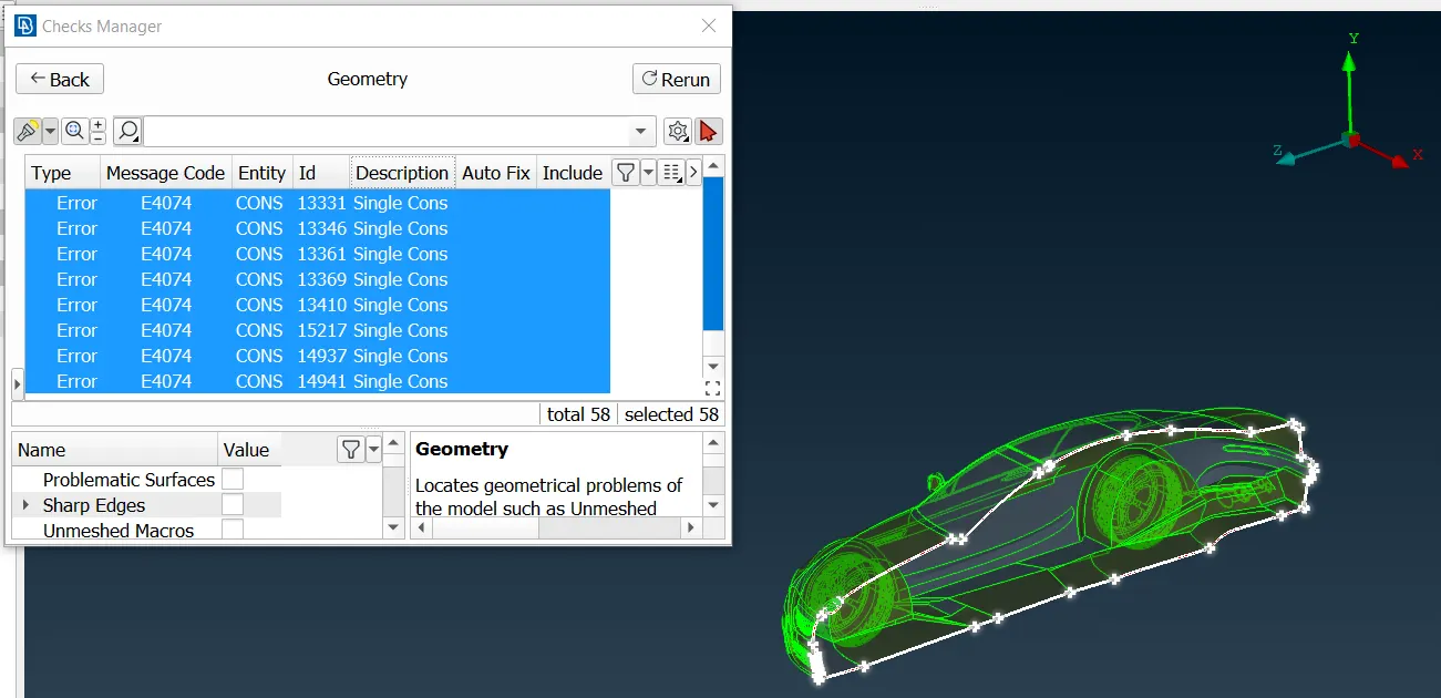
- Using the geometry check, all the surfaces that need to be fixed (single cons, triple cons, overlapping features) are identified.
- Half the car is deleted which will be redone using symmetry later.
- Using tools such as paste, cut, new, etc., clean up the car geometry part by part under the topo deck. Make sure to clear up all intersecting surfaces, multi-layered surfaces, sharp edges, and correct distorted surfaces.
- Curves can be created and used as blueprints for recreating surfaces that had to be deleted for created meshing and analysis of compatible surfaces/geometry.
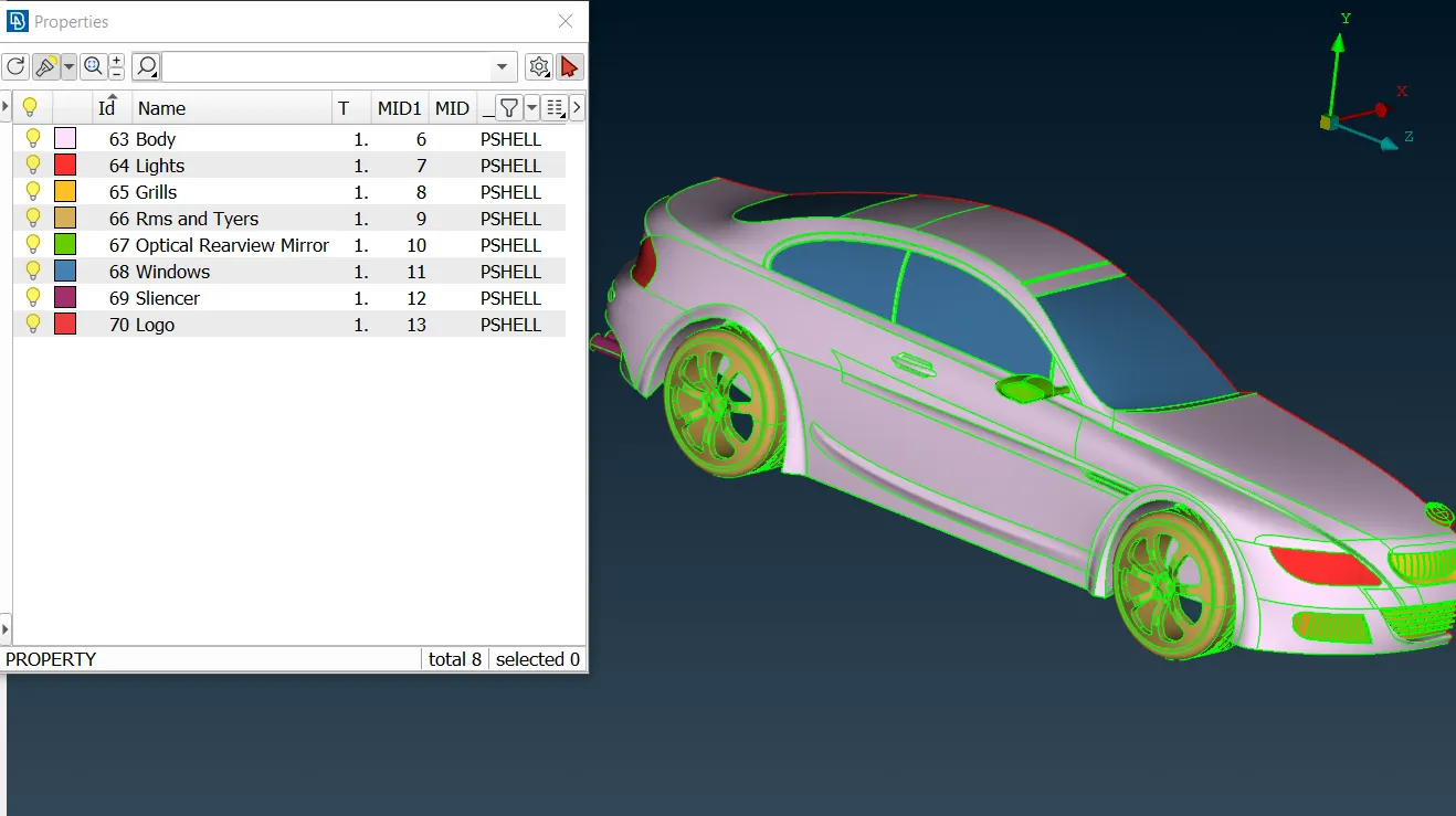
- Once the half-car geometry is ready, relevant PIDs are assigned.
- The half-car geometry is ready for surface meshing.
- Mesh
lengths are applied as follows:
1. Body - 3 mm
2. Lights - 4 mm
3. Grills - 1 mm
4. Rims and Tyres - 2 mm
5. Optical Rear-view mirror - 2 mm
6. Window - 2 mm
7. Silencer - 3 mm
8. Logo - 1 mm - For the above-mentioned mesh lengths, relevant maximum and minimum mesh lengths are also applied.
- By switching to hidden mode, off meshes can be viewed. We can use reconstruct which usually reduces off meshes by a great margin.
- Using tools such as move, and split under mesh deck as well as reducing minimum mesh length (if required), these off-mesh elements can be corrected.
- The car body is meshed last and only perimeter length is applied to cons that are not connected to other PIDs. This ensures that no meshed surfaces are deleted.
- Once all PIDs are meshed and ready, using the copy under transform tool, the meshed half is completed using symmetry.
- Some single cons may be generated which can be corrected easily.
- A geometry check is also performed as well.
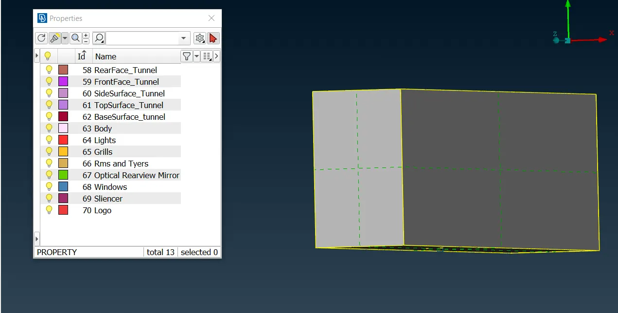
- Now, to create the wind tunnel geometry, points are created to aid in creating curves which then, aid in creating the wind tunnel geometry.
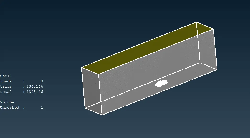
- An approximate of 1310mm is calculated as the maximum length of the car. Using this as ‘x’, the top face of the wind tunnel is set to ‘3x’ distance. Similarly, the front and back faces are set at ‘4x’ and ‘6x’ respectively. The sides are at ‘x’ distance from the car and the bottom face is set very near to the car.
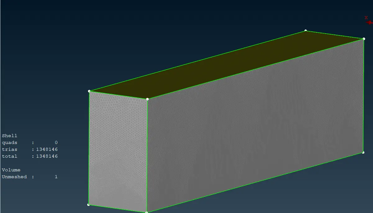
- The newly created wind tunnel is assigned PIDs and mesh with 20mm as target length at the bottom and 100mm at the top with the mesh varying from 20 to 100mm at the sides.
- Once the surface mesh is performed on the wind tunnel, we move on to the volumetric mesh.
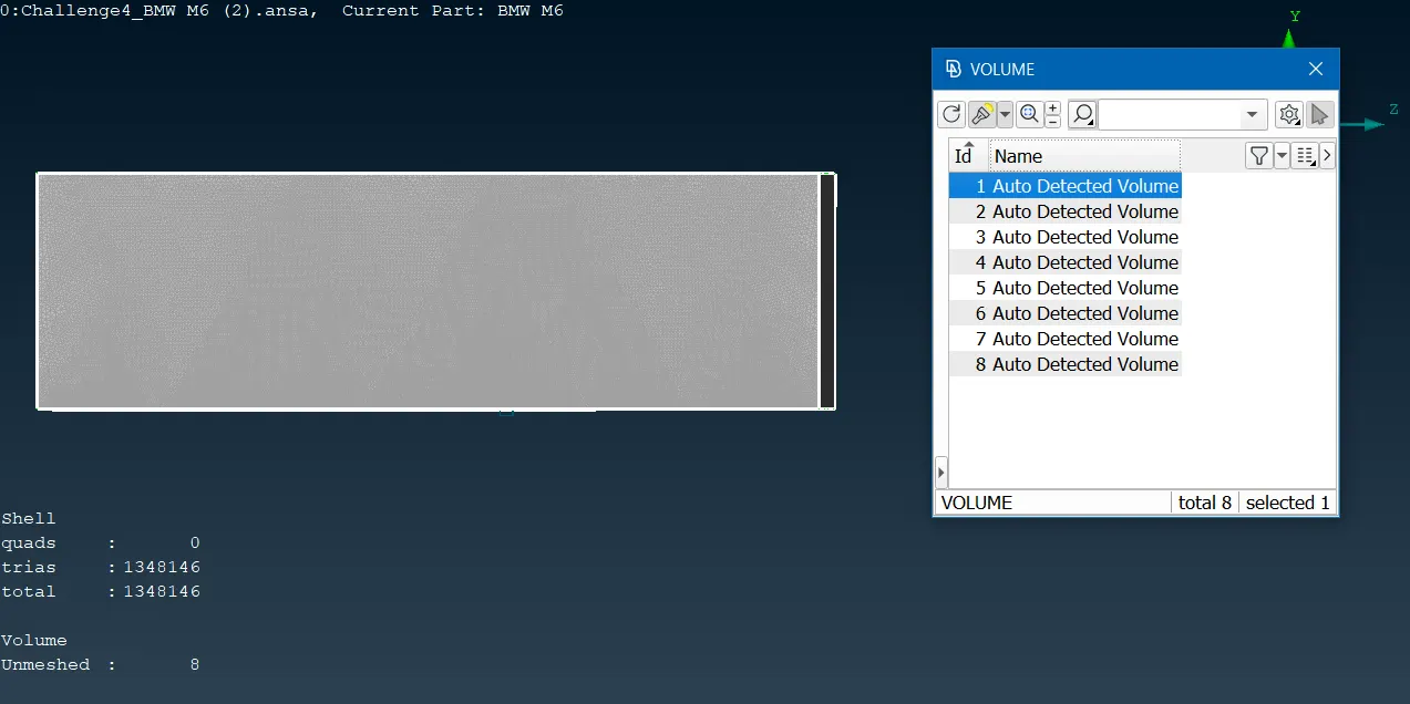
- Using automatic define, the whole database is defined for volumes. Only the volume between the wind tunnel faces and the car is required. The rest are deleted.
- Using remesh, tetra CFD is used to mesh the volume.
1. Imported Model
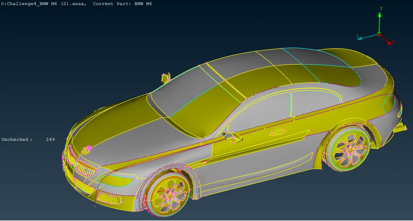
2. Topo Cleanup
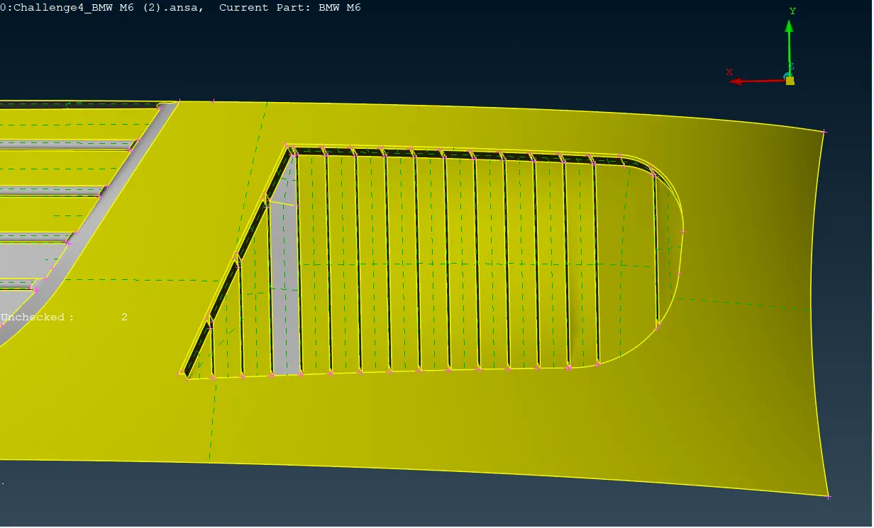
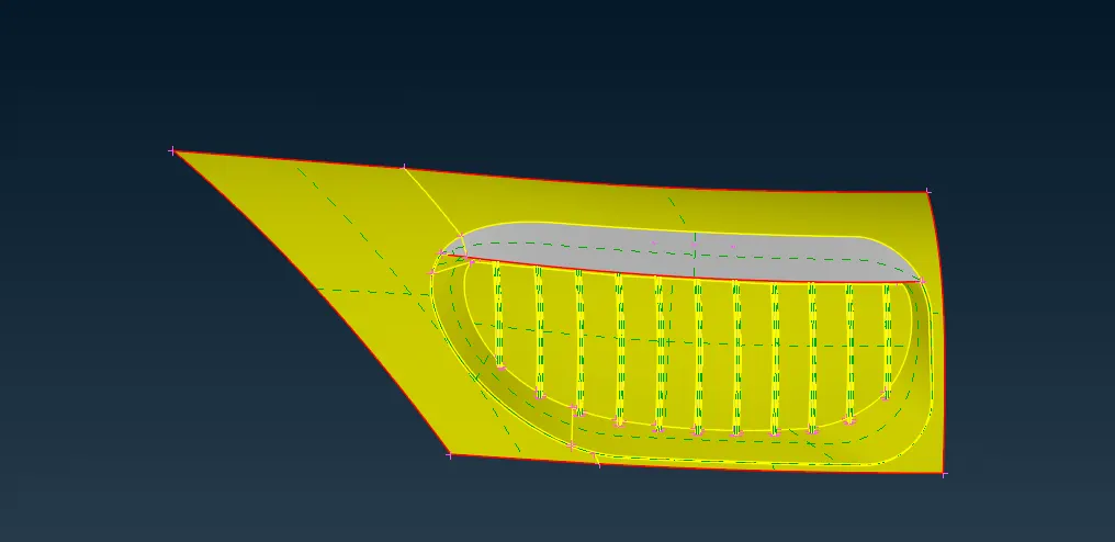
3. Geometry Check After TOPO Cleanup
4. PIDs Assigned
5. Meshed Geometry
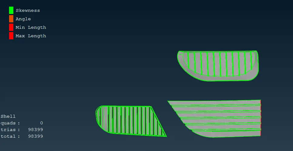
Grills
- Target length: 1 mm
- Min length: 0.5 mm
- Max length: 2 mm
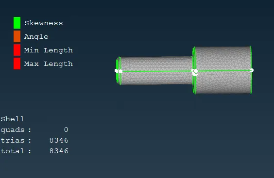
Silencer
o Target length: 3 mm
o Min length: 2 mm
o Max length: 3 mm
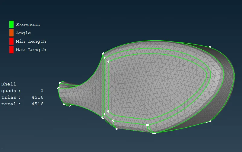
Rearview mirror
- Target length: 2 mm
- Min length: 1 mm
- Max length: 3 mm
Body
- Target length: 3 mm
- Min length: 1 mm
- Max length: 5 mm
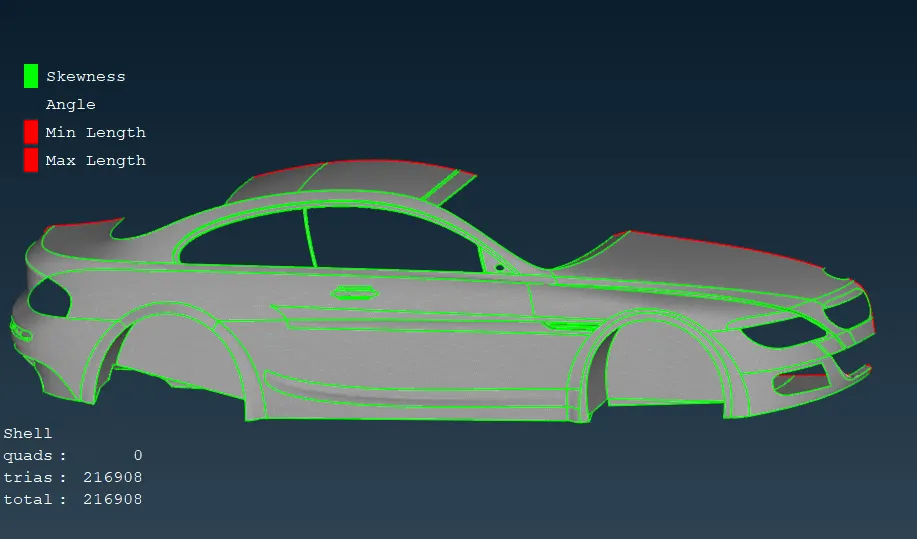
6. Performing Symmetry
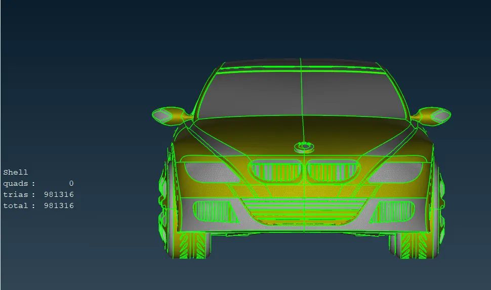
7. Wind Tunnel Geometry
8. Surface Meshed Wind Tunnel
9. Volume Between The Wind Tunnels And The CarSurface Meshed Wind Tunnel
CONCLUSION
First, half-car geometry is deleted. The topo is cleaned up accordingly. Relevant PIDs are assigned and surface mesh is done on the half car geometry. The geometry is completed using the symmetry tool. The wind tunnel is created and the surface is meshed and then the volume is defined and meshed also.
Link for downloading Model:-https://drive.google.com/file/d/1YLxstnHgwPZYocjgpBVqMnil1mmgXt0B/view?usp=drive_link