Week 4 Challenge : CFD Meshing for BMW car
Aim:
CFD Meshing of BMW Car
Objective:
To learn topology, geometry clean-up, and meshing for BMW car. Also, Perform meshing with the given Target length and elements Quality criteria. After meshing the half model, Do symmetry to the other side.
Target lengths for the different parts of a model are as follow:
Body - 3 mm
Lights - 4 mm
Grills - 1 mm
Rims and Tyres - 2 mm
Optical Rear view mirror - 2 mm
Window - 2 mm
Silencer - 3 mm
Logo - 1 mm
Steps:
Part1:
Our Model has so many single cons so apply topo to the entire model and topo will work, it will join the two or three cons together respectively.
As our model has uneven surfaces so to make the surfaces acceptable use the fine option from auxiliaries. If we have to do cons resolutions of the entire model in one shot then go to the mesh deck and apply perimeters and macros equal to 1 mm so that it will improve the cons resolution of the entire model. It will ultimately reduce the distance between two cons which is equal to 1mm in order to make a good surface finish or for better resolution.
If two single cons are near to each other then we can join them by using the paste option.
Topo cleanup for grills is done by deleting unnecessary surfaces from grills to remove triple cons, delete un-wanted hot points, and single cons are removed by patching the surfaces using New-Coons/Fitted options.
Topo cleans up tires and side mirrors and head and tail lights including removing triple cons by deleting the unwanted surfaces.
For a logo, the overlapped surfaces were identified and separated by projecting those surfaces on the hood and deleted followed by removing small edges which may cause errors during meshing.
The lower car body needs to correct by removing unwanted protruding parts and the part of the lower body intersecting with tires needs to be deleted to make tires a free volume. For keeping track of different parts in the lower body ‘cons2curve’ is used to have a blueprint of deleted surfaces with help of which new surfaces are created.
Geometric checks are performed to have no single cons present in the model and possible triple cons are removed by deleting it using the universal delete option.
Before creating surface mesh the cons and small edges that have lengths less than the minimum mesh length are identified by measuring the distance between cons and solved using the ‘cut’ option in order to avoid mesh failing the mesh criteria at these small surfaces.
PIDs are assigned using the PID manager which is present at the top deck for all parts of the body.
Part2:
Individual elements mesh with respective mesh lengths with minimum and maximum lengths.
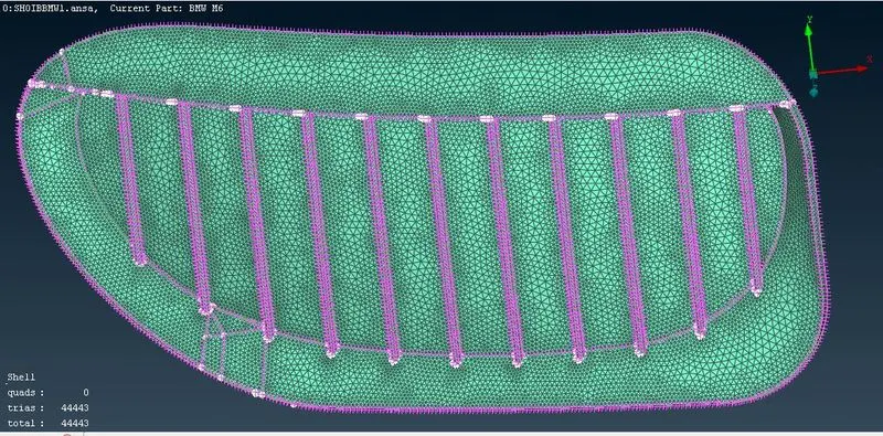
Like Grills are isolated and given a mesh length of 1mm with minimum and maximum lengths of 0.5mm and 1.5 mm with triangular elements.
The mesh is seen in Hidden Mode and ENT wise, which will show off elements that are violating the criteria. So we need to remove off elements by using options such as MOVE, SPLIT, RECONSTRUCT, and SMOOTH the grid respectively. from this, we can improve our meshing.
Once the off element`s numbers are reduced to 0 then meshing is done successfully, and a Similar method is used for other PIDs.
Symmetry needs to be performed on the other half of the car in which all the components with mesh are copied directly to the other side using the Transform option from the top side option list.
Part3:
Data for the wind tunnel are as follows:
The wind tunnel dimensions are if x is the length of the car then,
The front of the wind tunnel is 4X from the car.
The rear of the wind tunnel is 6X from the car.
The top of the wind tunnel is 3X from the car.
The side walls of the wind tunnel are at X from the side portion of the car.
The bottom of the wind tunnel is in close proximity to the wheels.
Points are created by using the ‘Relative option’ in points of Topo Deck.
Topo Deck- points- relative –points- select points. After the points are created join these points from the bottom plane by ‘create curves’
Once the curves are created for the top and bottom then create a surface with help of the ‘New’ option in ‘faces’
Topo – Faces - New - Fitted - will open PID manager window - create new PID-double click on it to create a surface on it.
As the analysis of what happens over the surfaces of the car is of importance so the bottom of the wind tunnel should have a good resolution as compared to the top portion as it is relatively at a larger distance than the bottom. So mesh length of 20 is taken at the bottom and 100 for the top portion.
As the front and rear of the car are connected with the top and bottom surfaces then the mesh length for these surfaces should vary from 20 to 100 from bottom to top portion. This gradual variation can be achieved using the Spacing option from the perimeters section of the Mesh deck.
Perimeters - Spacing – Geometric – factor of 1.1 and d-min of 20 successful applications of this will be indicated by upward pointing arrows.
Mesh is generated by applying Spot mesh for individual surfaces.
Procedure:
Import CAD Model into ANSA.
Open ANSA ⇒ File ⇒ Open ⇒ Select the model to be imported.
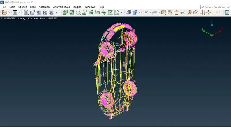
Then we need to enable the shadow mode and need to keep the model in the PID mode.
Click on Shadow mode
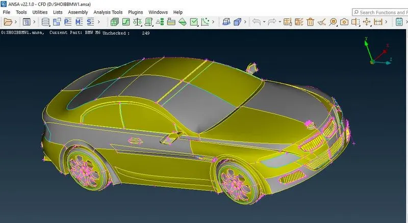
BMW M6 Model: Before topological cleanup.
Enable all the cons and crosshatches to perform the geometry clean-up and also go to the mesh parameters and put the values of the length and the macros as 1 mm this produces the smooth curves. Making coarse resolution into Finer resolution.
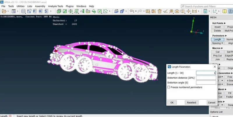
Deleting the model in half.
The most important job is to split the car in half. This helps to save the work time since we need to do work with only half the file and finally, we will mirror it.
Proper orientation for deleting: Press F1 (Top plane)
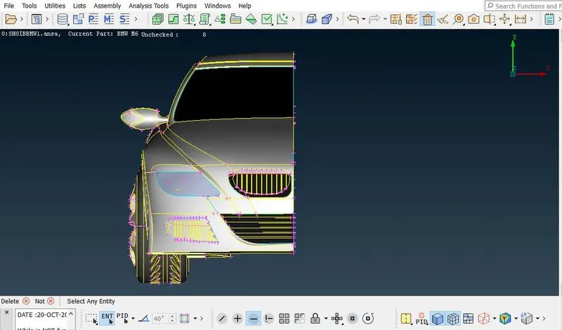
While deleting into two half, deselect the BMW logo because it is not symmetrical on both sides.
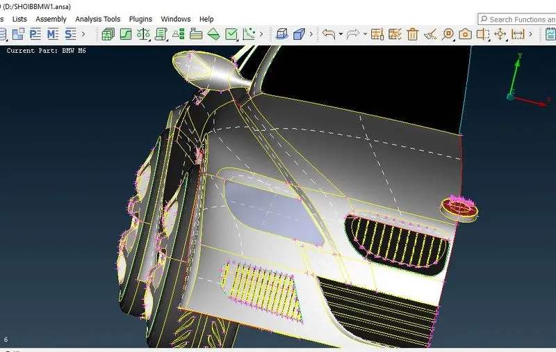
Topological clean-up surface by surface
Now, the topology is cleaned up by deleting unwanted faces and edges, so that ANSA does not create unnecessary volumes by doing so all the triple cons and double cons are converted to single cons.
In the grill region, there are some overlapped surfaces and some triple cons that are tackled and deleted successfully because we perform the simulation on outer geometry hence the inner geometry is not required.
To remove and delete all the unwanted surfaces we used the Cut and delete tool.
Geometry clean-up of the grills is done by the following procedure-
To perform the geometry clean-up of the grills we have to first isolate that surface and lock it up by the NOT option and then lock up the geometry.
we have to delete the unnecessary surfaces on the grill.
Go to faces new coons fitted to faces and cut and enable the parametric cut and then cut the fins that are present on the grill.
perform to all fins and remove the unwanted surface.
Go to faces - new - coons to join the deleted surface by using these options and this way the geometry clean-up is done.
We have to perform similar operations on the intake grill.
Before:
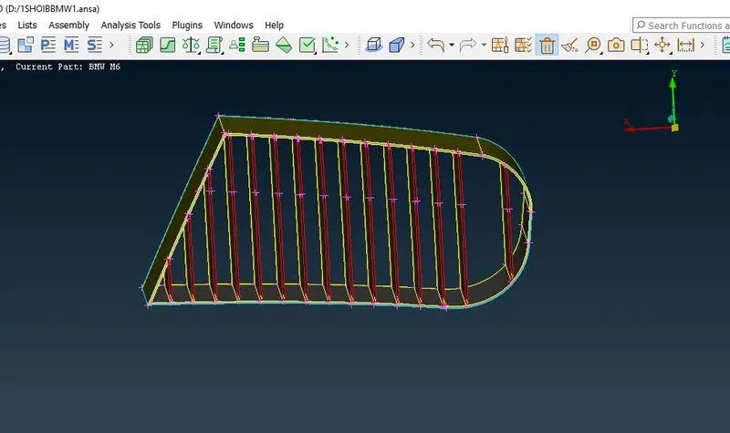
After:
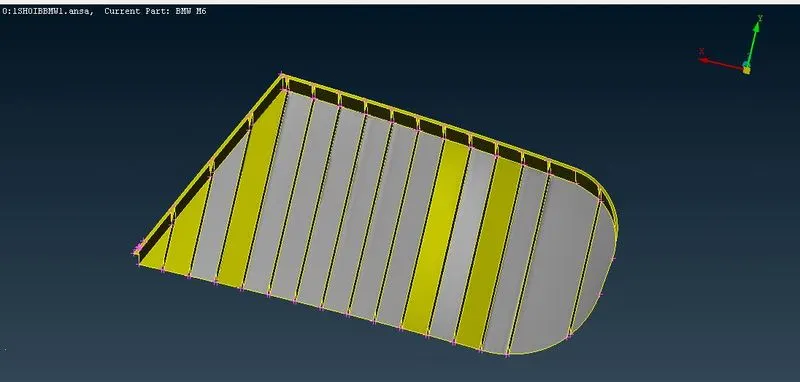
To perform geometry clean-up for BOTTOM GRILL we have to isolate the part and lock it by using NOT mode and LOCK mode
Primarily we have to delete the unwanted surfaces by using the DELETE option and make sure it is in ENT mode.
Go to CONS > PROJECT and project the cons of the grills onto the surface and delete the unwanted surfaces
Sometimes we can create a new surface by deleting the old surface according to our necessity.
Go to FACES > NEW > COONS /FITTED to join the deleted surfaces by using these options and the geometry clean-up is completed.
Remove the interior extruded surfaces by using the DELETE option.
Before
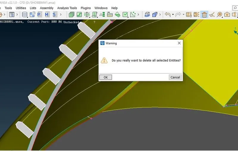
After
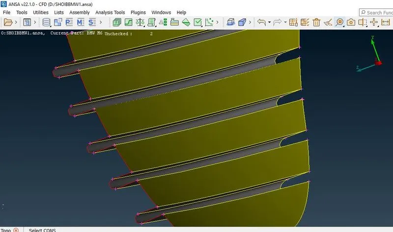
Before
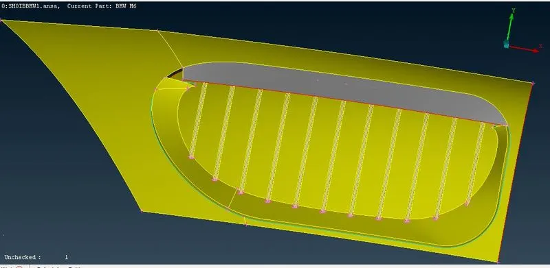
After
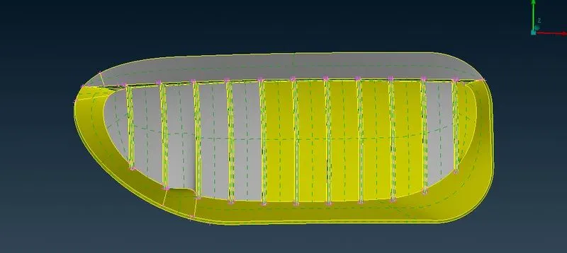
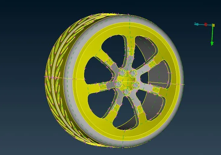
Now we go for the cleanup of the tires and the rim section we get the following
First, isolate the tires by using NOT and LOCK Mode.
Then DELETE the common surfaces present in between tires and rims
Thus geometry clean-up of tires is completed
Remove the unwanted surface on the bottom part and also not associated with wheels.
After performing geometry clean-up for all parts perform geometry checkup by hiding single cons.
Before
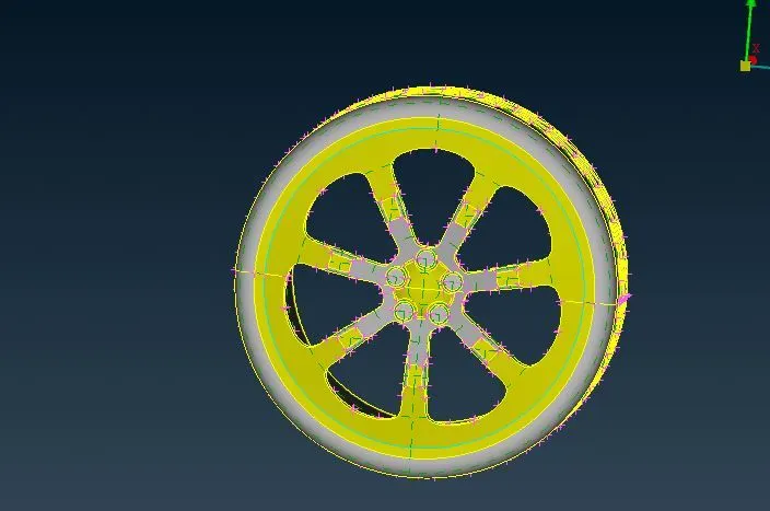
After
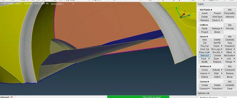
Before
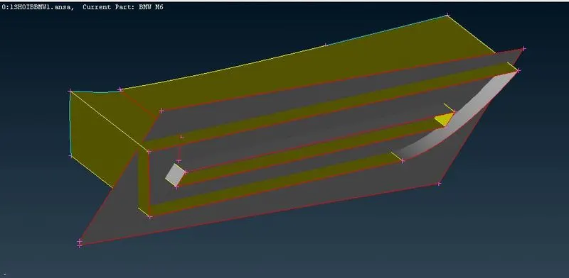
After
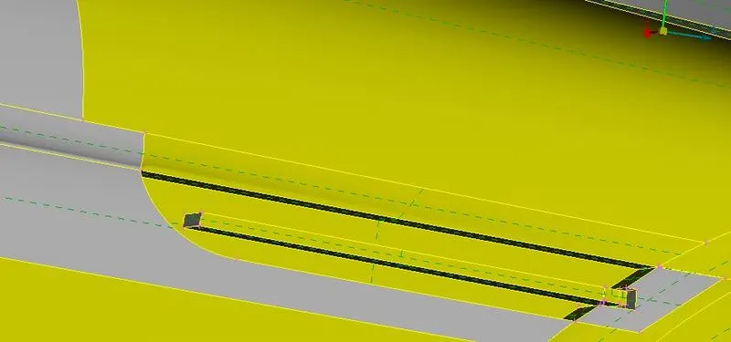
In this region, we deleted the inner extra surfaces and created a hollow region and, we also did some changes to the upper BMW surface (cut some extra surfaces to remove triple cons).
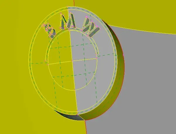
There are several triple cons present in the window region as well, due to the presence of the volume element instead of a surface element in this region. To fix this we deleted all extra surfaces.
In the base we have some extra intersect and sharp surfaces intersecting the tires so we deleted and create a new region with a less sharp corner.
As we discussed earlier we do not require the inner volume so we have to delete the unwanted surfaces from the headlight and backlight as well.
In this region also some triple cons are present that are gradually solved as we deleted the unwanted surfaces.
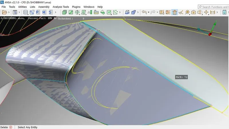
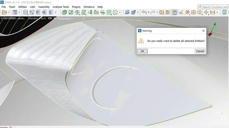
Next, the mirror is to be cleaned by deleting the exiting surface and creating new surfaces
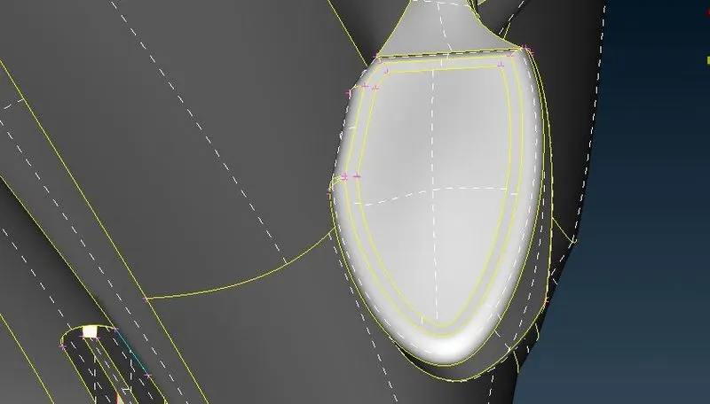
Here also we deleted the inner surfaces and create a Hollow region.
To Generate the PIDs of the model, we use the properties tab to list them.
ASSIGNING RELEVANT PIDs:
To assign PIDs for the given figure, go to the PID MANAGER tool.
It shows all the PIDs assigned to the figure.
First, isolate the body and lock the figure. Then go to > PROPERTIES it shows the PIDs assigned to the body so we have to rename them as BODY by creating a new PID.
Repeat the same process and assign PIDs to all parts of the car.
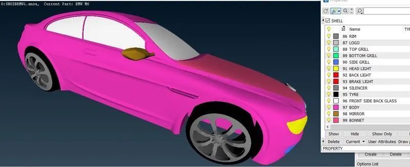
The car model after being assigned the PIDs.
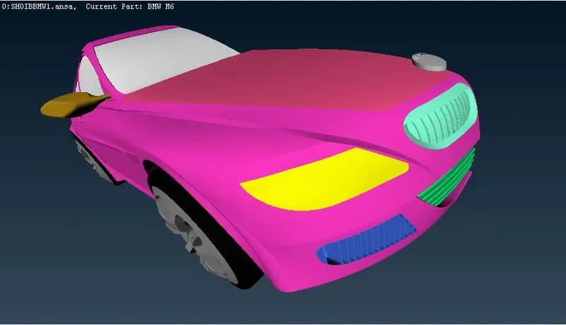
Due to different target lengths given for meshing, that's why we mesh the components individually.
In the body, the PID region is in contact with other PIDs so that the mesh length variation at the boundary region of 2 different PIDs causes the mesh to erase or cause mesh failure in that particular region. Therefore, while entering the perimeter under a length in the mesh. select the region which is not in contact with other PID regions. This helps in avoiding the mesh being erased and can later be edited to erased and can later be edited to erase the off elements.
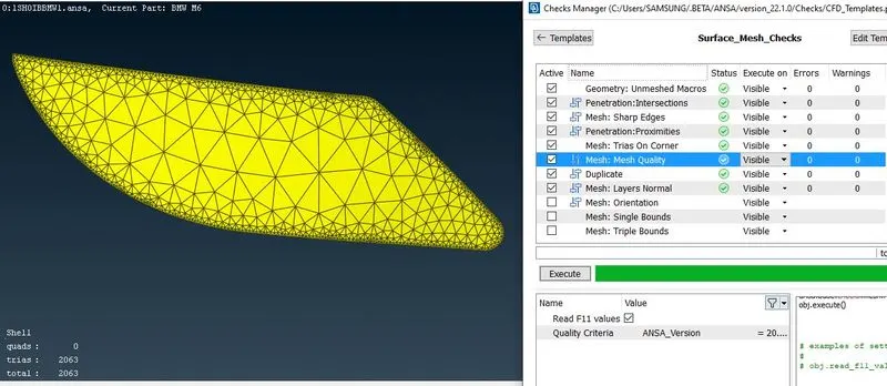
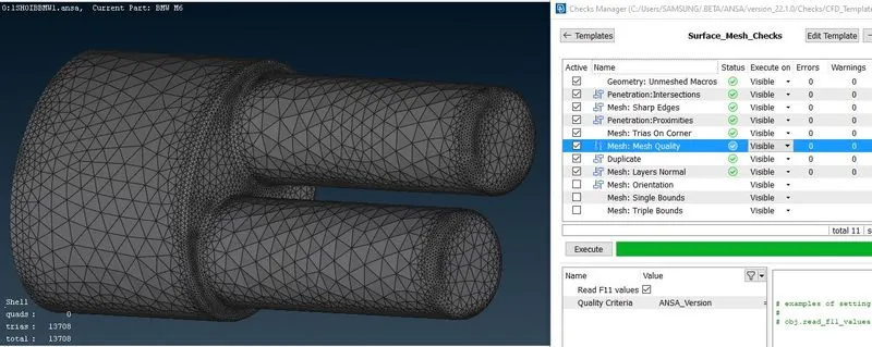
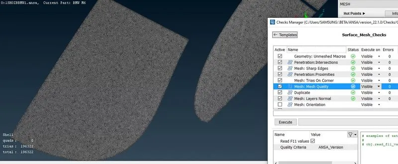
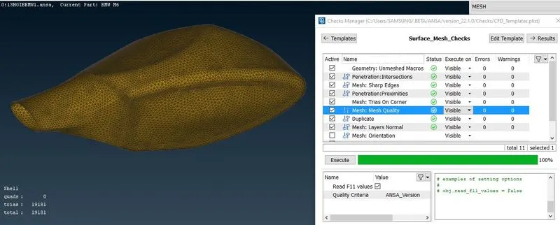
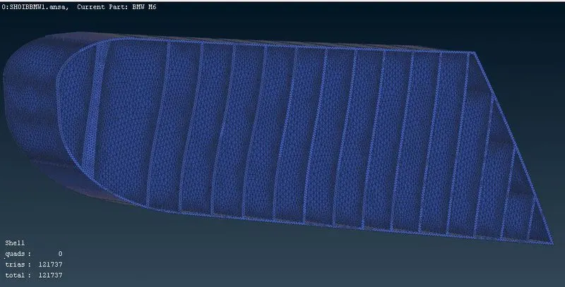
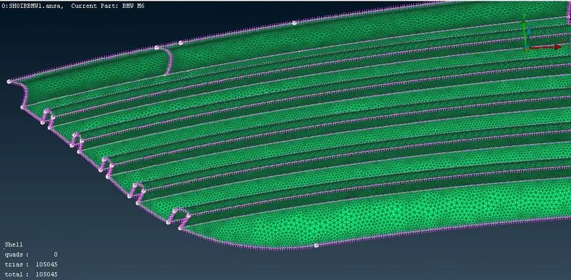
SURFACE MESH: Mesh the surface according to the given parameters.
Body - 3 mm
Lights - 4 mm
Grills - 1 mm
Rims and Tyres - 2 mm
Optical Rearview mirror - 2 mm
Window - 2 mm
Silencer - 3 mm
Logo - 1 mm
Goto MESH > PERIMETERS > LENGTH and mesh the surface
Use TRIA elements and the mode of mesh is a CFD mesh.
After the surface mesh checks can be done and eliminate the errors that occurred in the mesh model using tools like move, reconstruction, and split.
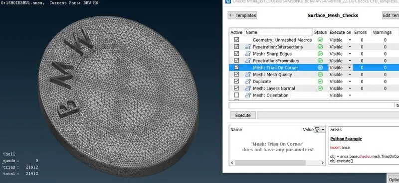
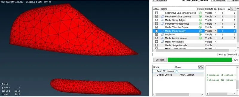
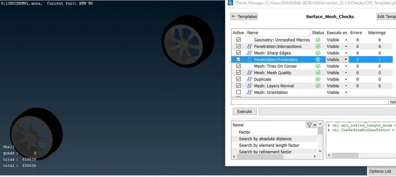
ELIMINATION OF SKEWNESS, MIN LENGTH, AND MAX LENGTH ERRORS:
Go to mesh quality criteria and adjust the parameters to standard values.
For example, if the minimum length is = 1 mm so the limit is set to 0.2 mm, and the maximum length = is 4 mm so it is set to 5 mm.
Apply the changes and the errors that appeared on the left side of the screen and we have to eliminate those errors and it is shown as OFF elements
Goto SHELL MESH > RECONSTRUCT to reconstruct the model to eliminate min length and max length errors and make sure that the elements are within our limits
To find the skewness error go to skewness and right click then click on the show only it will show only the skewness error.
This error is rectified by using the GRIDS > MV SURF option or GRIDS > PASTE options and also by reconstructing the structure
After eliminating all errors it shows OFF ELEMENTS is zero.
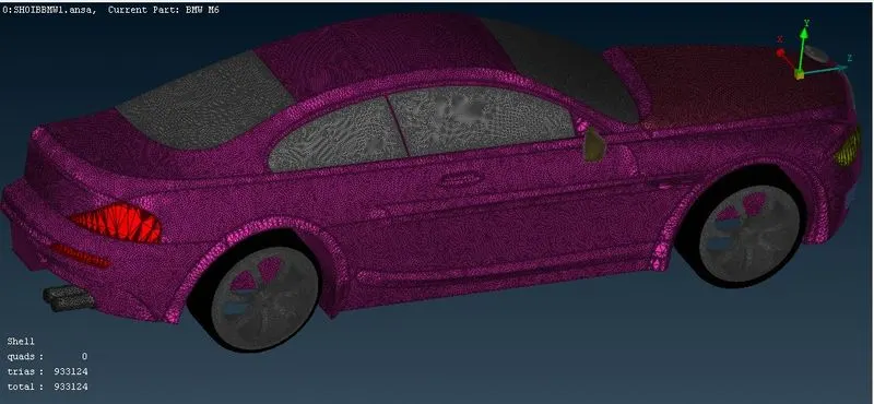
As we discussed above this is a symmetry model so we have a tool called transform where we can copy, move and link the model as per required.
But for this model, we 1st use the copy option and then chose three points to join the other half and then execute.
SYMMETRY:
Go to TOPO mode and perform the symmetry operation for the model.
First, we have to isolate tires and lock the remaining model.
Goto SYMMETRY > COPY and copy the entire model and select the MIRROR 3 POINT PLANE and select three nodes then it replicates the other image.
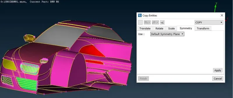
For safety use the TOPO option to make all cons to double cons by selecting the entire model
In order to perform symmetry on the front tire goto POINTS > ON COG to locate the center part of the tire and use undelete option to retrieve some part of the tire and locate the midpoint of other tires
Perform symmetry Operation by copying tire and translation using two nodes.
Change the threads on right-side tires using the same option.
The whole car model
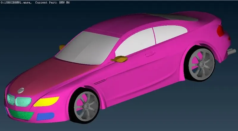
Creating the wind tunnel and volumetric mesh of the wind tunnel
To create the wind tunnel first calculate the length of the car:
Dimension of the wind tunnel
Car length-1300 approx so,
The Front of the car is 4x that is 5975 mm and the Rear of the car is 6x that is 8680 mm.
From the Top of the car is 3x that is 4323 mm and from the bottom is 75 mm.
From the center plane - the left and right are 1x which is 1300 mm.
Then go to> POINTS > NEW and create points in all directions according to the directions of the wind tunnel.
Create three nodes that are responsible to draw a plane.
Goto surfaces > PLANE and draw a plane using those three nodes and replicate the same plane using translation symmetry.
Repeat the same procedure for the other two sides.
Goto CONS > INTERSECT to intersect all planes and delete the unwanted surfaces.
Thus wind tunnel is created and assigned PIDs to differentiate INLET and OUTLET.
Wind tunnel
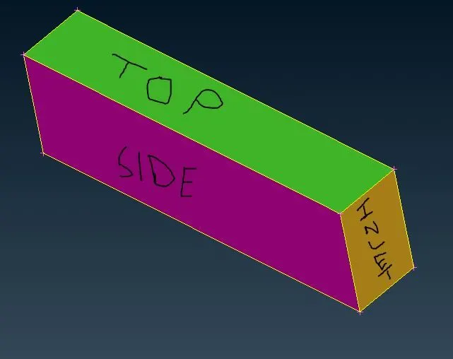
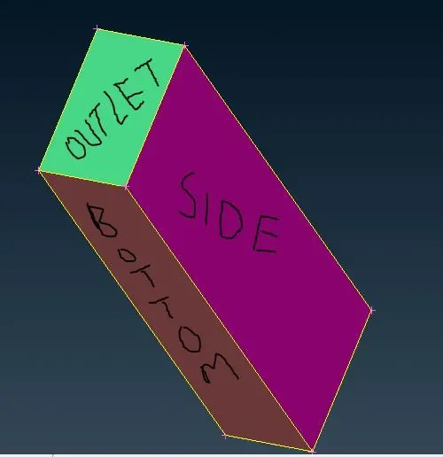
The meshing of the wind tunnel
Sides of the bottom of the tunnel of length 20 mm.
Sides of front and back as of length 50 mm.
Sides of top of the tunnel of length 100 mm.
Then go to PERIMETERS > SPACING > CONSTANT LENGTH and assign min value as 20mm and max as 100mm and assign to all front and backsides.
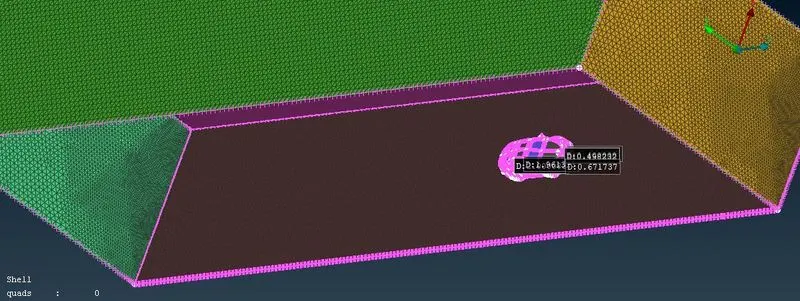
A geometry spacing is created with a factor of 1.1, with the smaller mesh elements increasing from the bottom to the top. This is because the top of the wind tunnel is less important compared to the bottom. finally, the wind tunnel has meshed.
Since performing volumetric mesh required 2-3 days so we did not perform it.
Result
For extracting volumes the geometry shall contain no triple cons, single cons, or intersections.
Sharp edges should have been carefully meshed as the mesh sizes may affect the shape of the geometry there and can further cause intersection errors.
Learning Outcomes:
Advanced surface cleanup.
Deleting unwanted faces Solving intersections, triple cons, single cons.
Making the solid simpler so as to detect volumes as intended.
Surface meshing tools.
Creating wind tunnel.
Volume meshing.
Conclusion:
Performed the given BMW car model topo clean-up and Surface mesh appropriately.
Create surfaces using the reference hot points by using relative points.
Surface meshing is done for different components and varying their mesh lengths.
The wind tunnel is created, and Different volumes of the car model are created.
Single volume is created of the car body so that it can be avoided at one go when creating a volumetric mesh.
BMW FILE:
https://drive.google.com/file/d/1OM97o_1J2LheQ024MXHzgggpidNIgK5j/view?usp=sharing