Week 4 Challenge : CFD Meshing for BMW car
Week 4 - CFD Meshing of a BMW car
Topology Clean-up:
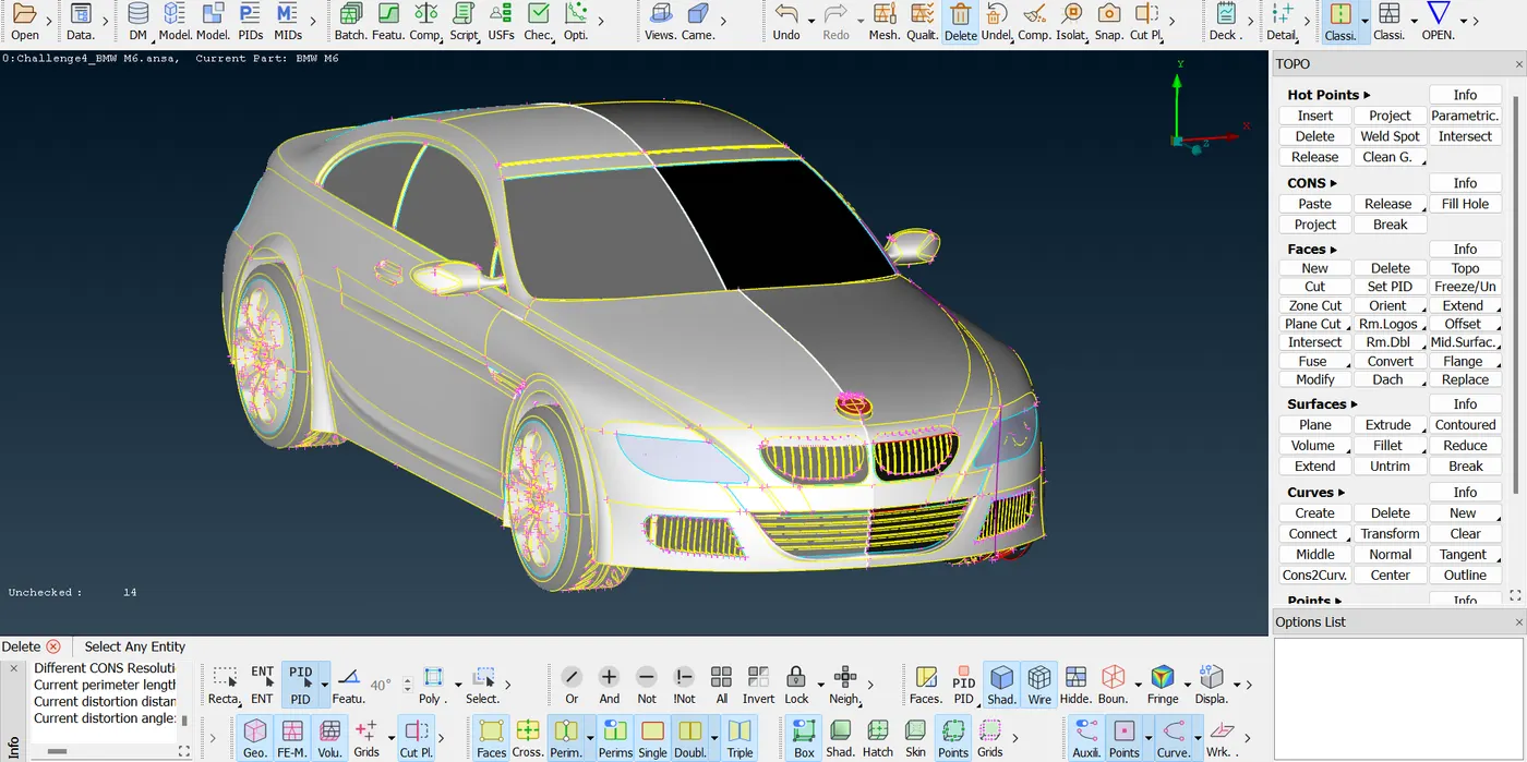
The CAD model of the car when loaded into the ANSA software, showed up a lot of geometric errors having incomplete single connected surfaces and additional triple connected surfaces. So it was required to clean up the unwanted surfaces and set up the geometry properly.
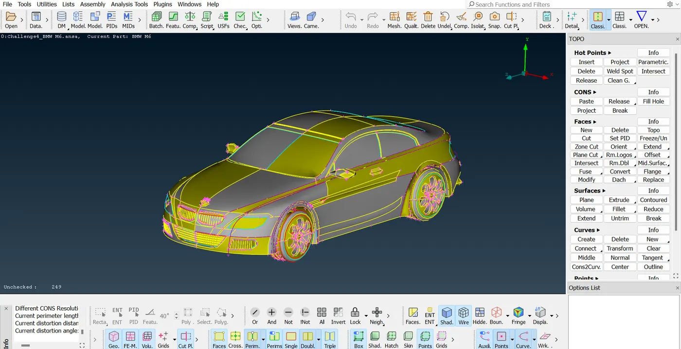
In the below image it can be seen that there are multiple triple connected surfaces and single surfaces indicated with blue and red colour respectively. These single connected surface can create gap which does not make the geometry watertight and the blue colour surfaces which are triple connected surfaces can create additional volumes which are not required while performing the volumetric mesh
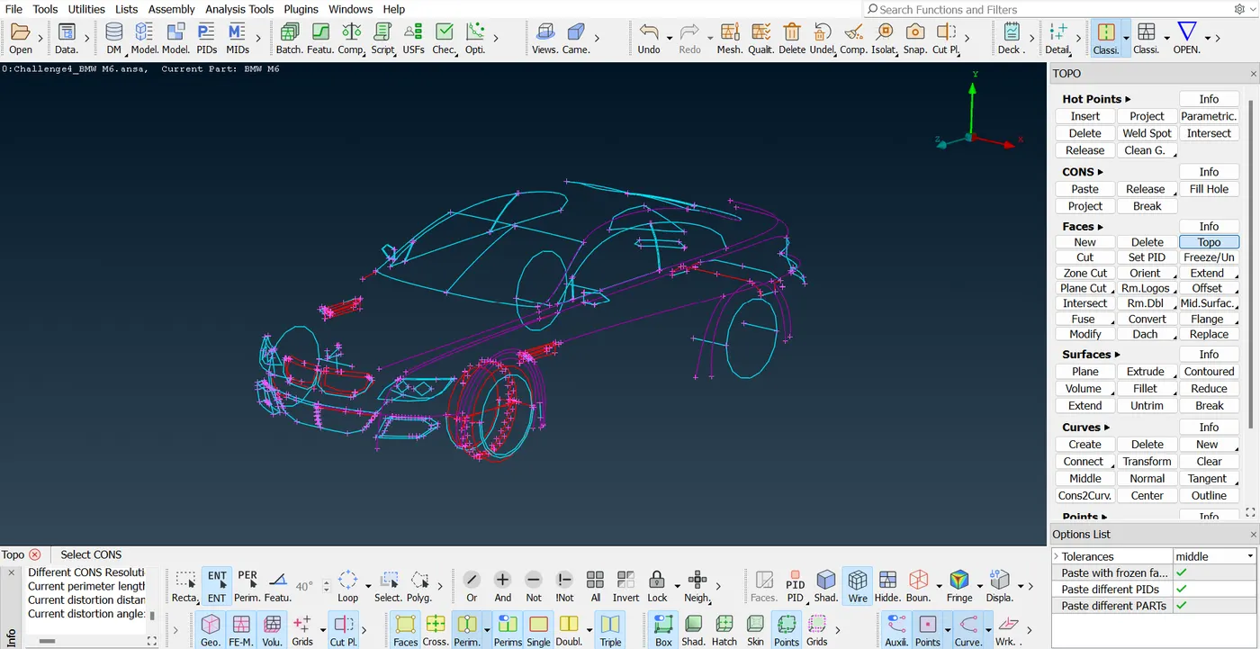
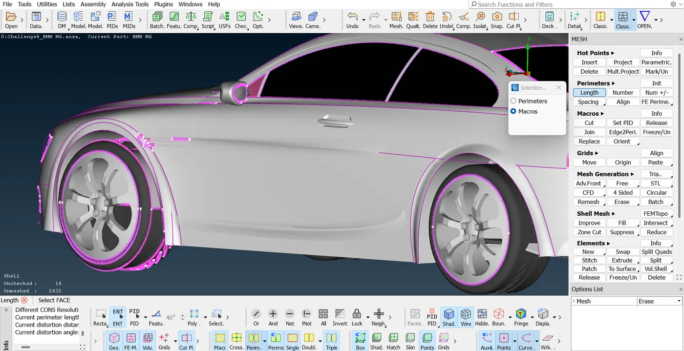
In order to make the geometry proper the curves and boundaries needs to have proper curvature, so instead of refining each and every single boundary separately a pre-mesh is created of 1mm so that it adjust all the surfaces properly. Also as the cad model is symmetric, so it is suitable to delete the half portion as the surface properties will be similar on the other side.
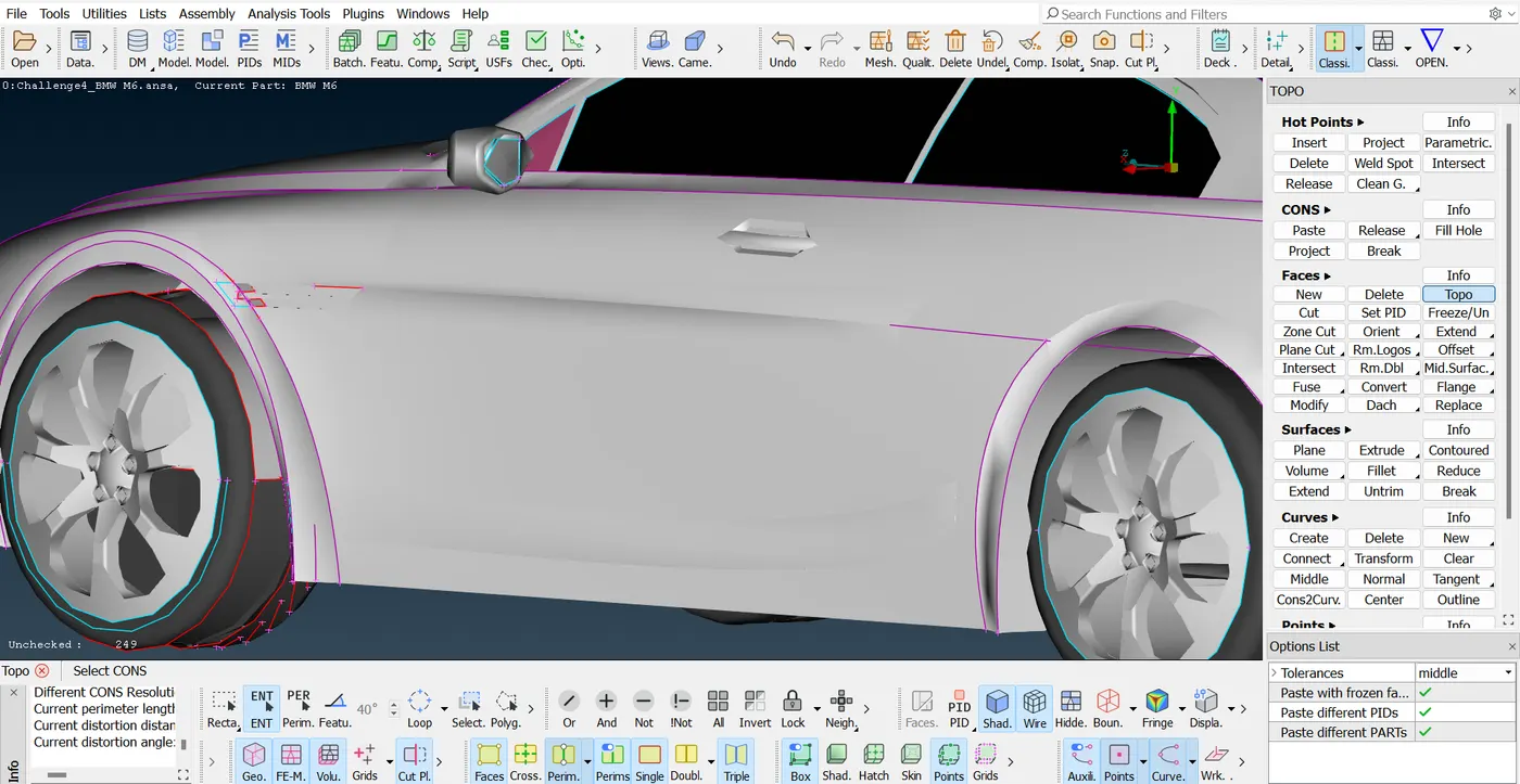
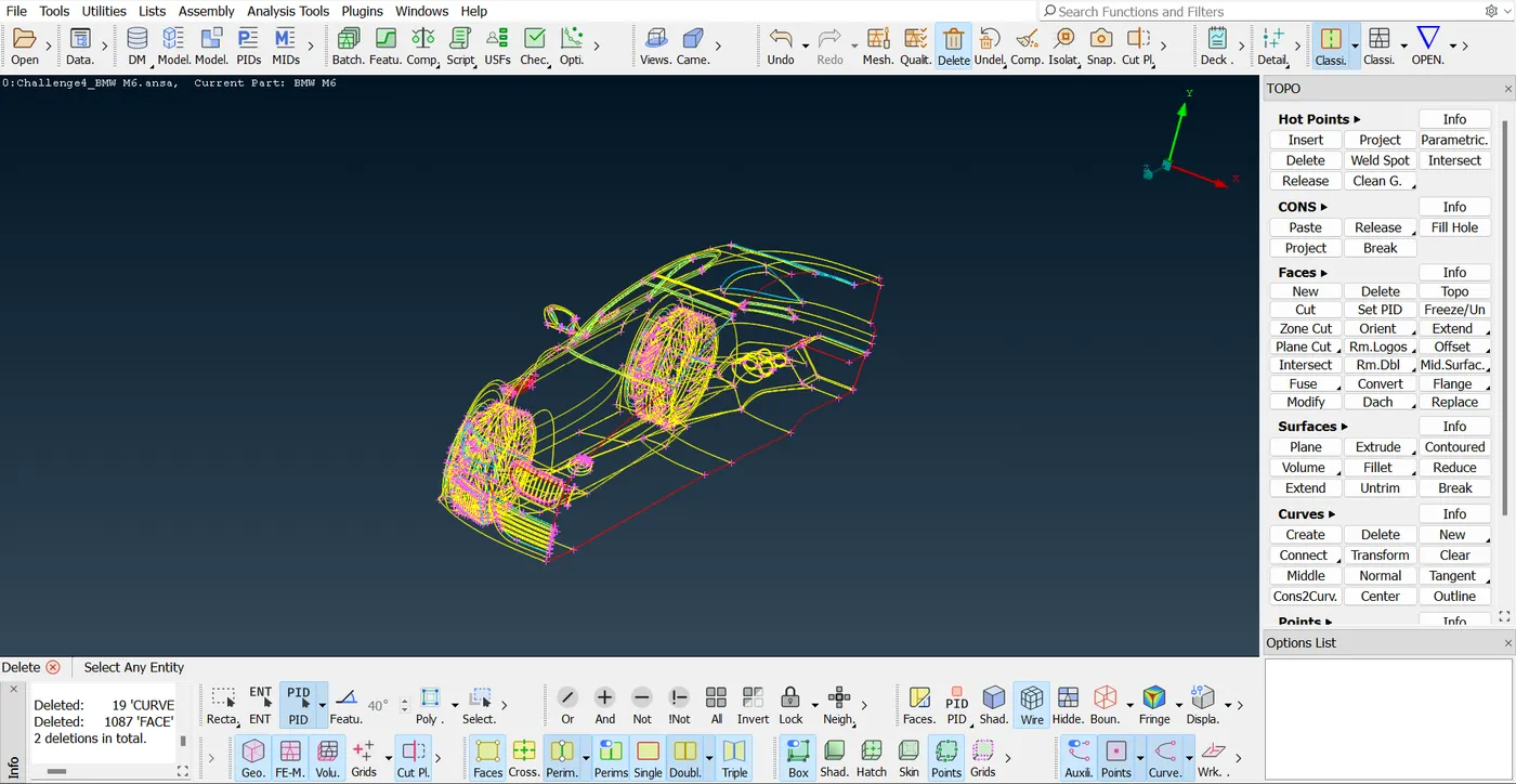
Deleting interior features
Here, this case is concerned with external flow analysis and the internal feature of the car including every component is not necessarily required. Thus all the interior features including small details are deleted from the CAD model.
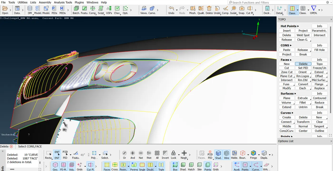
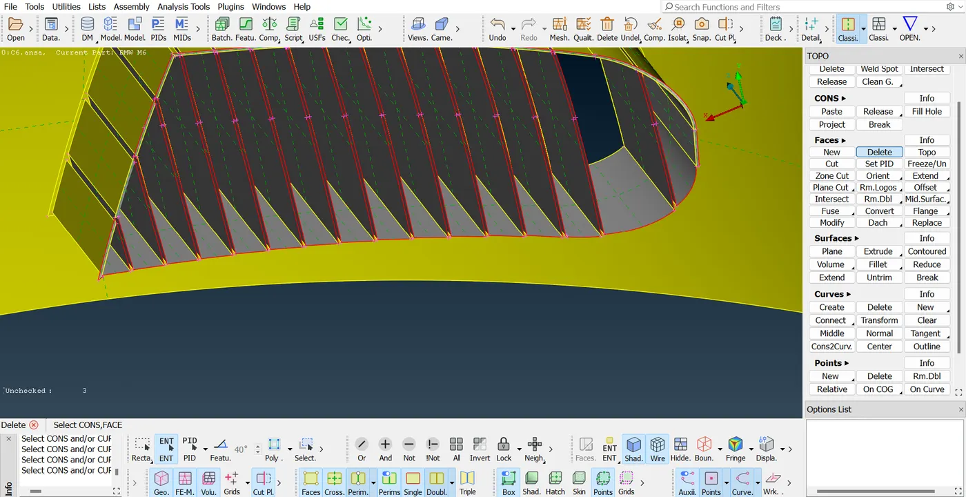
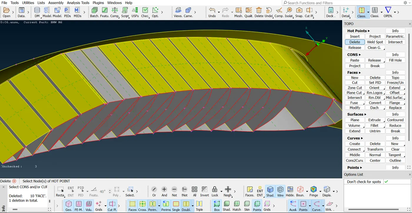
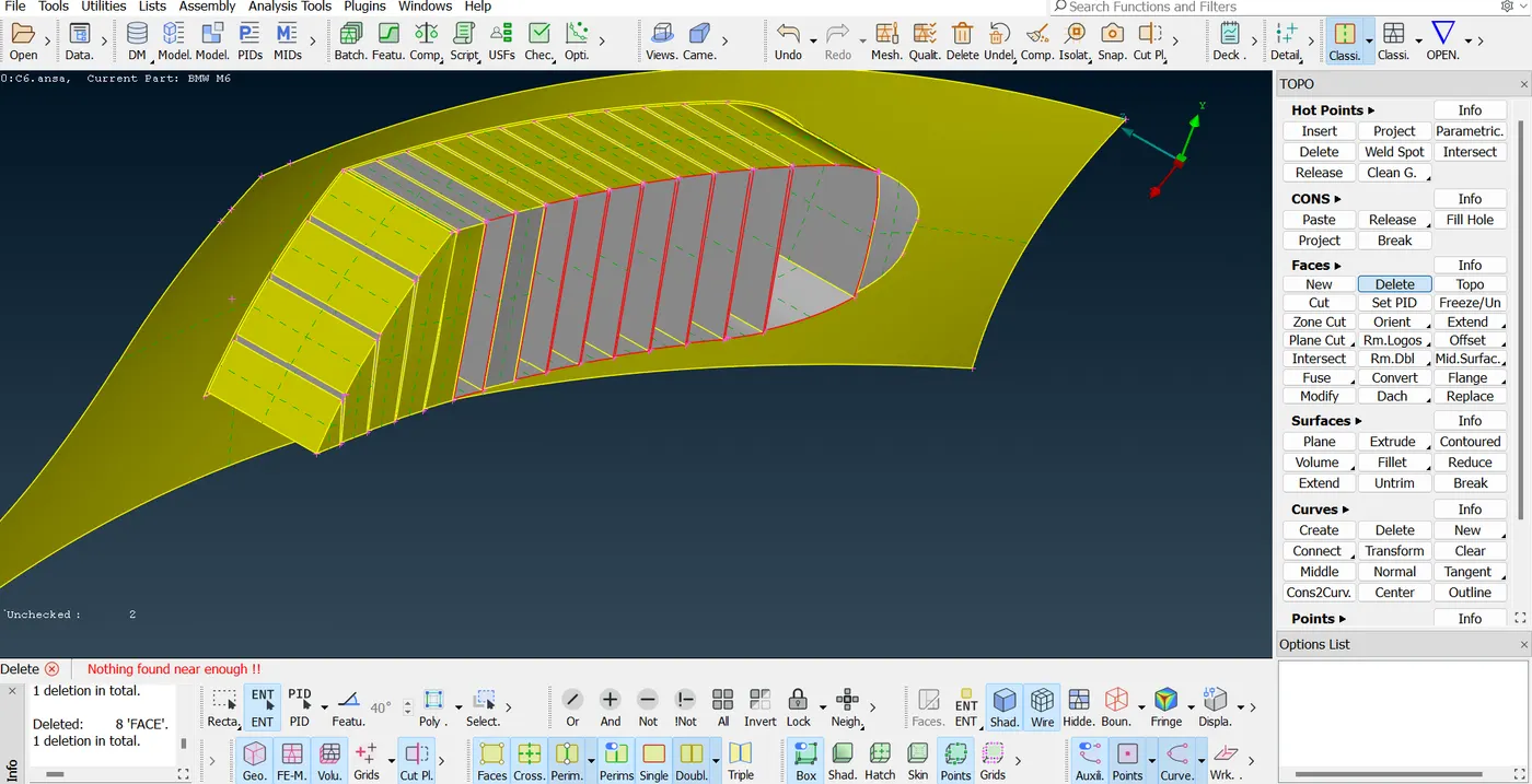
The grills located at the bottom section in the front part has gaps in between so it will create a hollow surface, therefore it is required to seal the surface from the outside such that the flow does not enter through the gaps. In order to do so the curves at the boundaries are deleted forming a single connected surface and hence each of the single surfaces are connected with the adjoint plates to create a complete boundary. After that the additional surfaces are created on the top and bottom which makes the volume of the grill sealed.
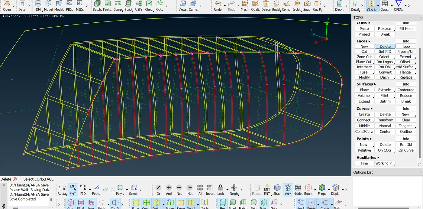
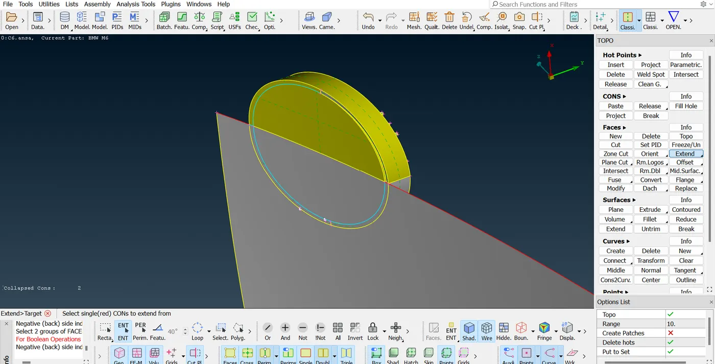
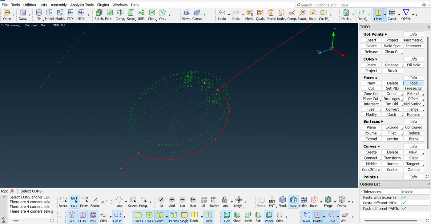
The below image describes the car logo which has overlapping surfaces hence forming a triple connected surface. These extra surface has been deleted and the edges have been adjusted.
For the another grill located adjacent to the previous one, similar operations were performed to seal the entire surface from the inside however the surface here was a little complicated, so a straight cut was made to separate the grill from the upper part and few of the hot points were projected to create a line which can join all the surfaces.
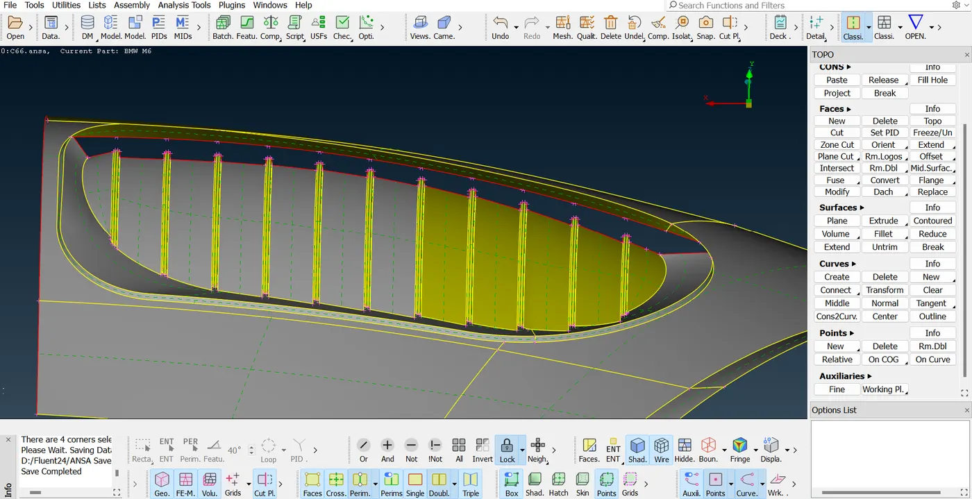
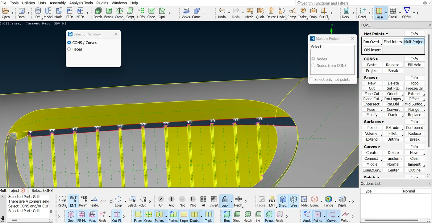
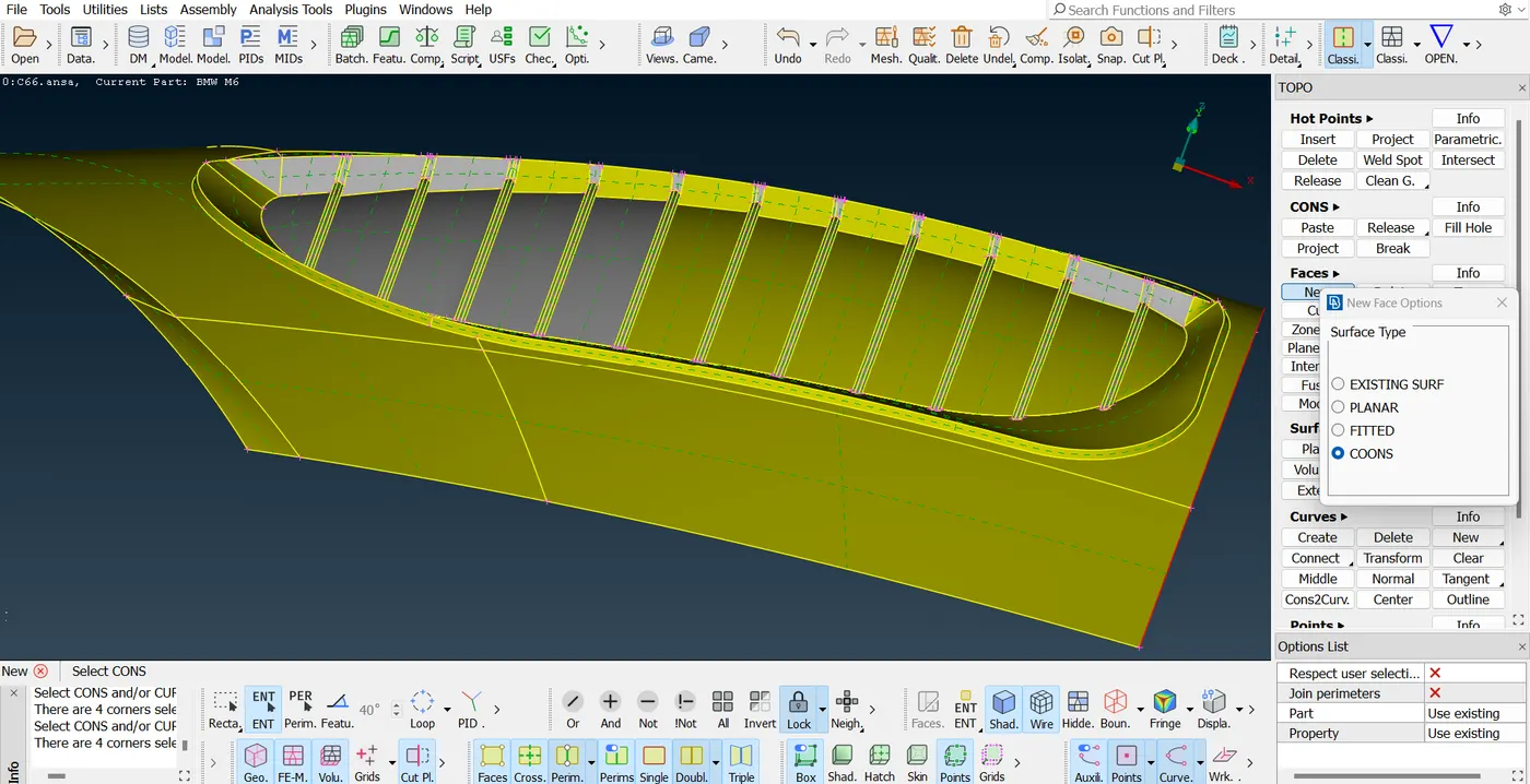
Secondly the following component being an external feature consisted a lot of intersecting surfaces hence few of the surfaces were extended in order to make the geometry simple and they were trimmed out based on necessity.
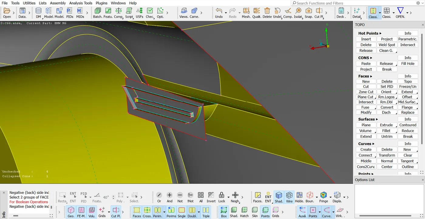
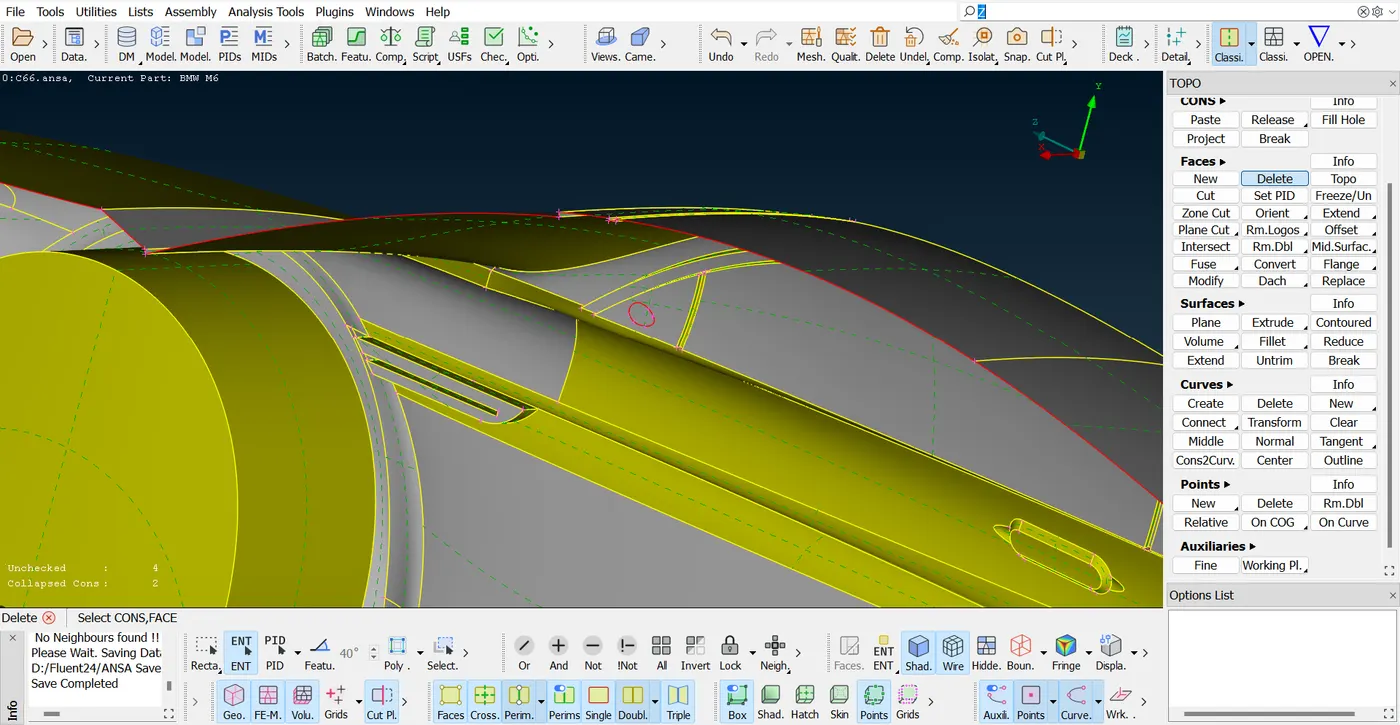
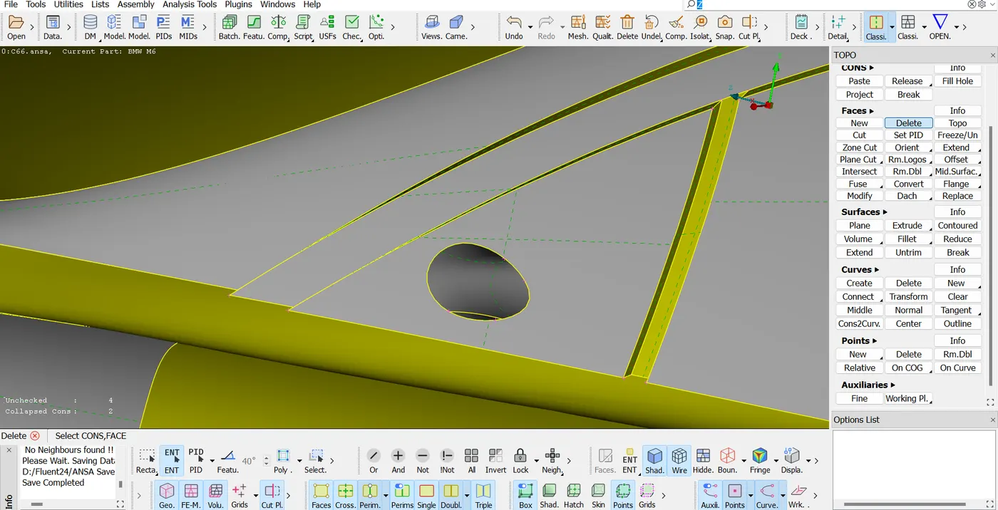
The mirror of the car was not an integrated part of the car body so in order to create a single volume of the car it was required to make the side mirror a sub-component of the complete body. This was done by deleting the interface which joined the car mirror to the body frame.
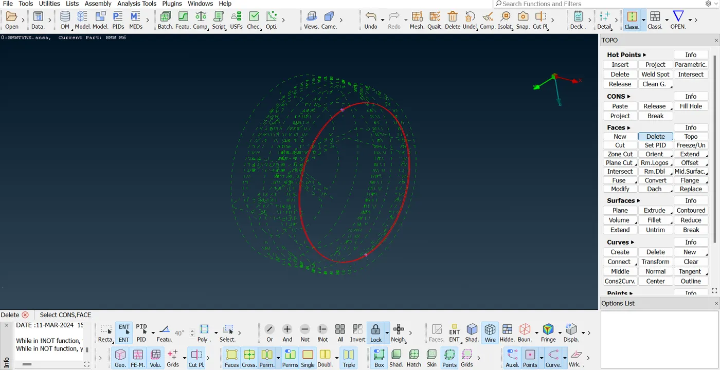
For the rims and tires the triple connected surfaces were deleted by deleting the overlapping surfaces and joining the near adjacent surfaces such that the whole can be made a single volume.
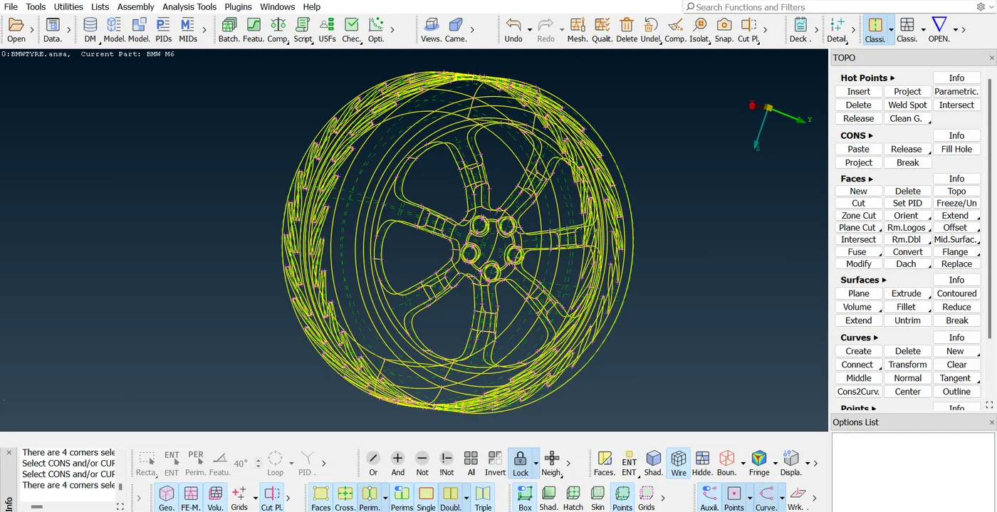
The interior features present at the bottom of the car had a lot of intersecting surfaces, hence these boundaries of the surfaces were projected as curves and it was planned to create a new surface at the bottom. Before that few of the intersections present inside the car body which were interfering with the tyres geometry were deleted by trimming unnecessary extended planes. After doing so new surfaces were patched in order to make the interior a single empty volume.
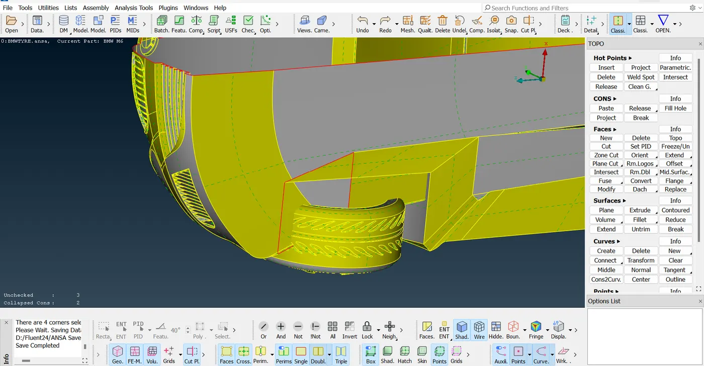
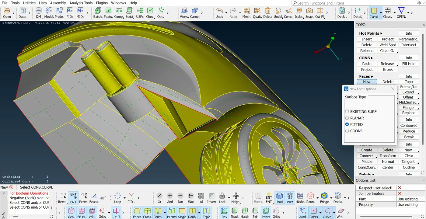
The below picture shows the silencer volume that is separated and additional cut on the upper geometrical face is made to join the surfaces which are present in between the silencer and the covering of the tyre.
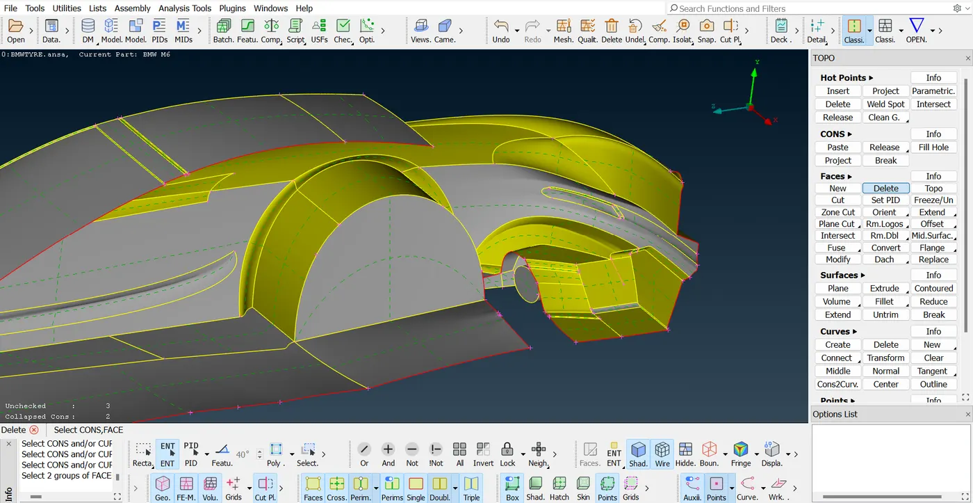
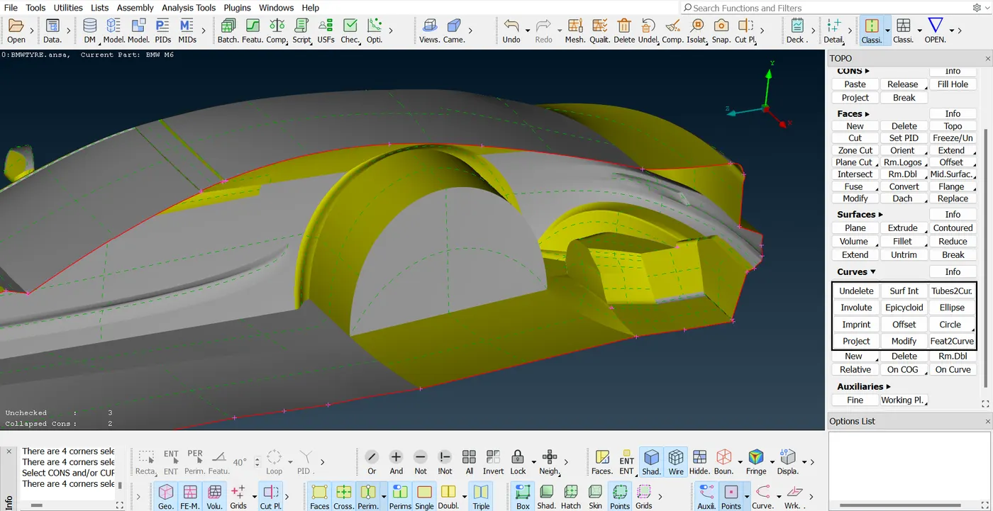
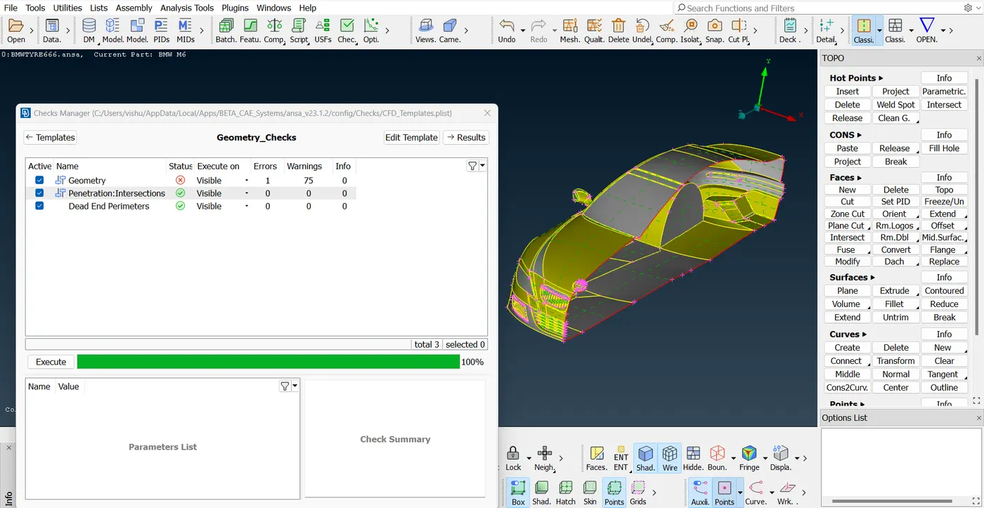
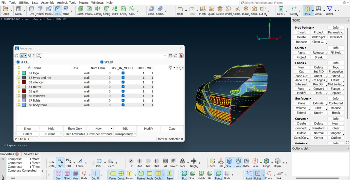
At this stage the geometric cleanup was complete as the analysis showed minimum number of errors and after the property IDs were assigned to the subcomponents of the car.
Surface Mesh:
Before generating the volume mesh it is required to create a surface mesh to assign the surface Discretization parameters and later they can be used to create the volumetric mesh The following mesh lines were provided to subcomponents as shown below:
| Number | Component | Size in mm |
| 1. | Bodyframe | 3 |
| 2. | Tyres and rims | 2 |
| 3. | Mirror | 2 |
| 4. | Windows | 2 |
| 5. | Lights | 4 |
| 6. | Grills | 1 |
| 7. | Logo | 1 |
| 8. | Silencer | 3 |
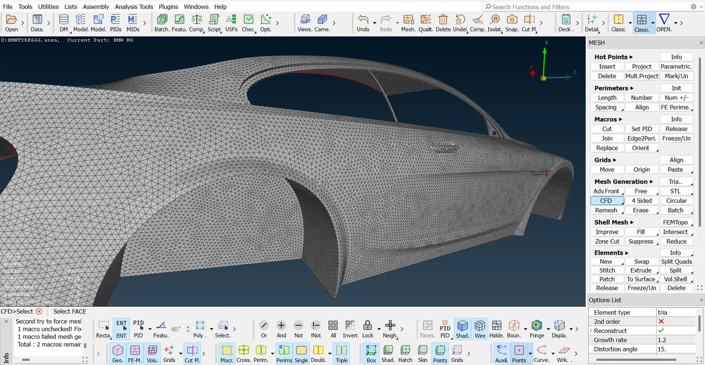
Surface mesh created for the body frame:-
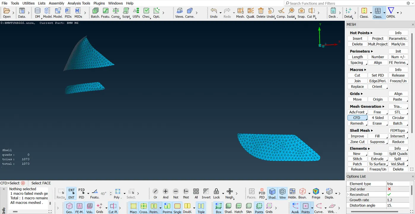
Surface mesh created for the lights:-
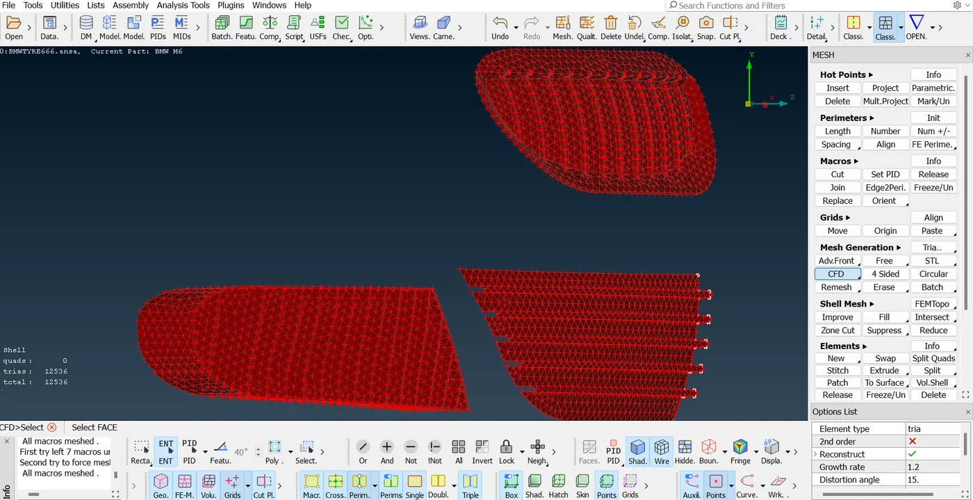
Surface mesh for the grills:-
The image attached shows a visual representation of the surface mesh for the entire car body. However this mesh is not acceptable as there are many of elements. Here the off elements contextualizes the damaged elements which should not exist in the meshed geometry while performing any analysis. For the following case three parameters namely minimum length, maximum length and skewness are considered.
The flow field which is to be simulated very much depends upon the parameters like skewness orthogonal quality and aspect ratio and the shape of the cells' smoothness and accuracy. The sales if distorted can create false solution for the flow variables and hence the result will not be accurate. Thus it is required to repair the cells in order to make a good mesh.
For the following components these Sales are repaired using Either by reshaping, reconstructing, smoothing, or changing the element quality.
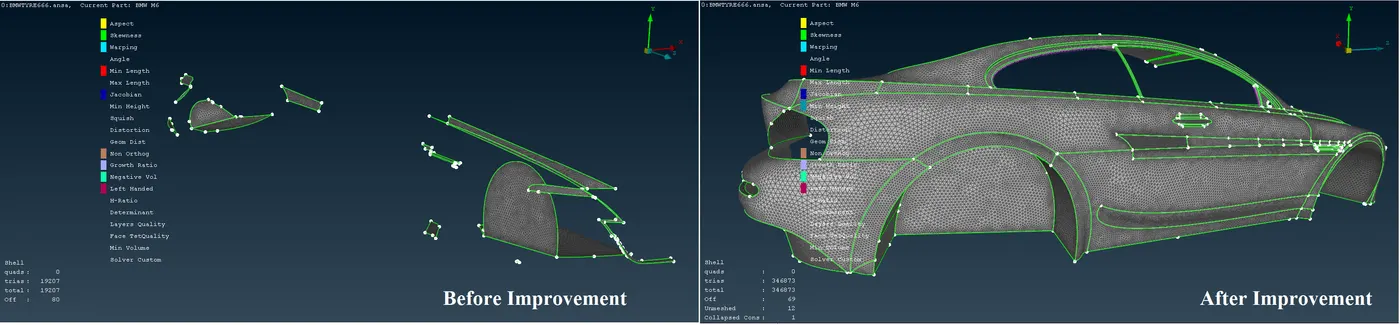
1. For the body frame:-
| Total Elements | 19207 |
| Off Elements | 80 |
After Improvement:-
| Total Elements | 346873 |
| Off Elements | 69 |
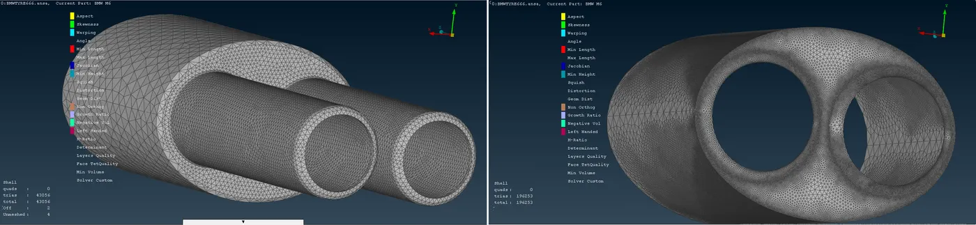
2. For the silencer:-
| Total Elements | 43056 |
| Off Elements | 2 |
After Improvement:-
| Total Elements | 196253 |
| Off Elements | 0 |
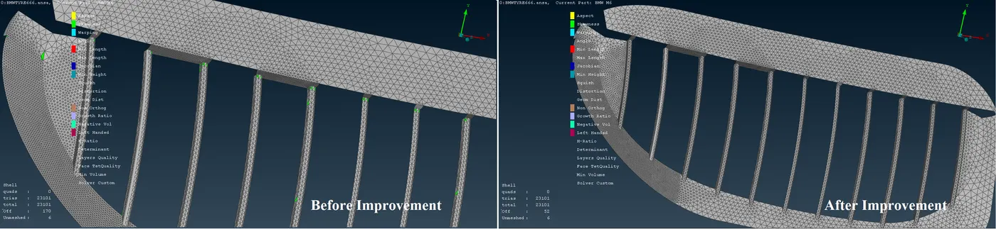
3. For the grills:-
| Total Elements | 23101 |
| Off Elements | 170 |
After Improvement:-
| Total Elements | 23101 |
| Off Elements | 52 |
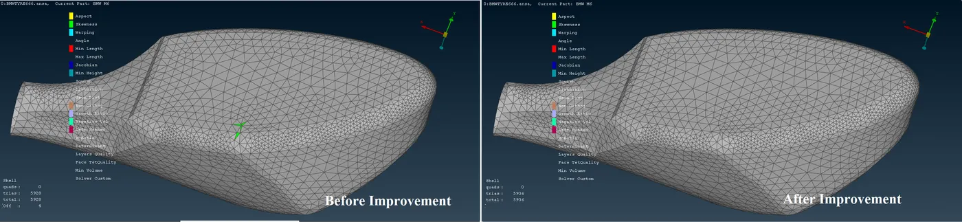
4. For the mirror:-
| Total Elements | 5920 |
| Off Elements | 4 |
After Improvement:-
| Total Elements | 5936 |
| Off Elements | 0 |
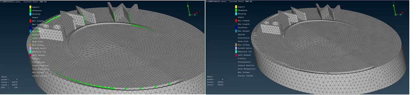
5. For the logo:-
| Total Elements | 10272 |
| Off Elements | 196 |
After Improvement:-
| Total Elements | 10256 |
| Off Elements | 0 |
Repaired Mesh:-
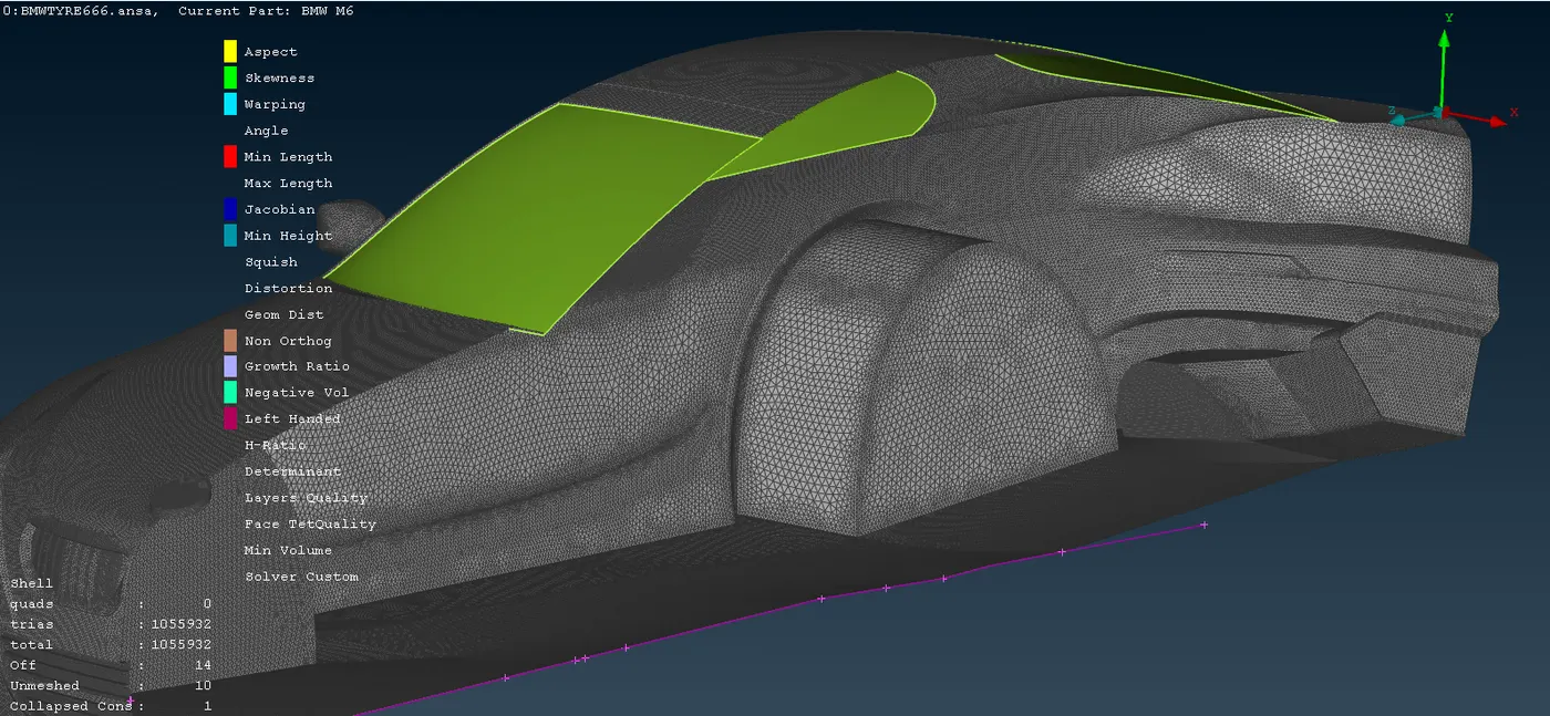
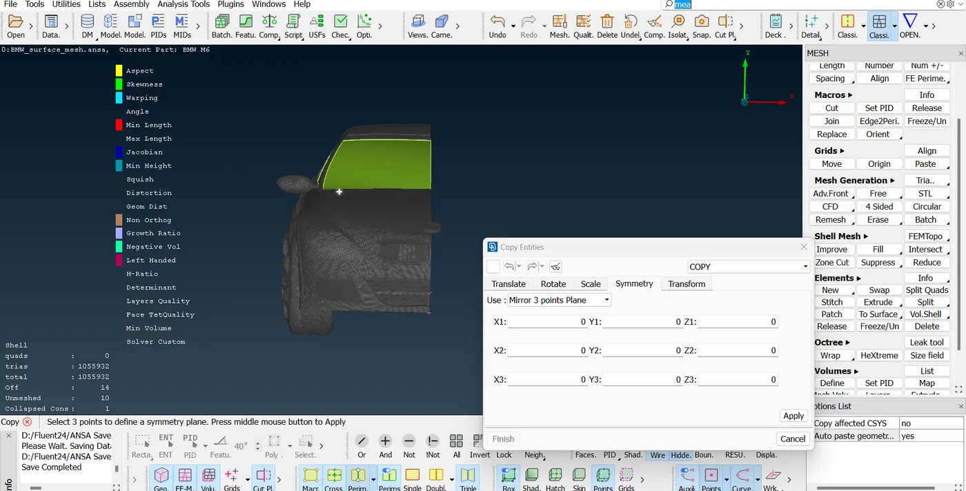
Now that half side of the car is meshed, the symmetry can be performed to mirror the half portion to the opposite side.
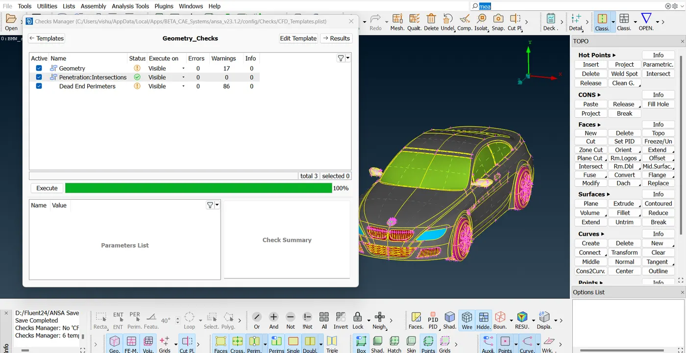
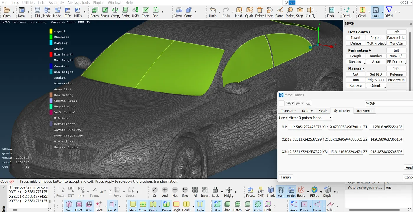
The mirroring of the geometry is done by selecting a three point metering option and the three points are selected such that it covers the entire model right from start to end. Consequently the gaps because of the single connected surfaces are and the unmeshed regions occurred after mirroring the geometry are remeshed to get a complete CAD model of the car.
Upto this point, the total triangular faces on the car are 2104542.
Modelling the Wind-tunnel:
With the suitable distance as shown in the image, the wind tunnel is modeled.
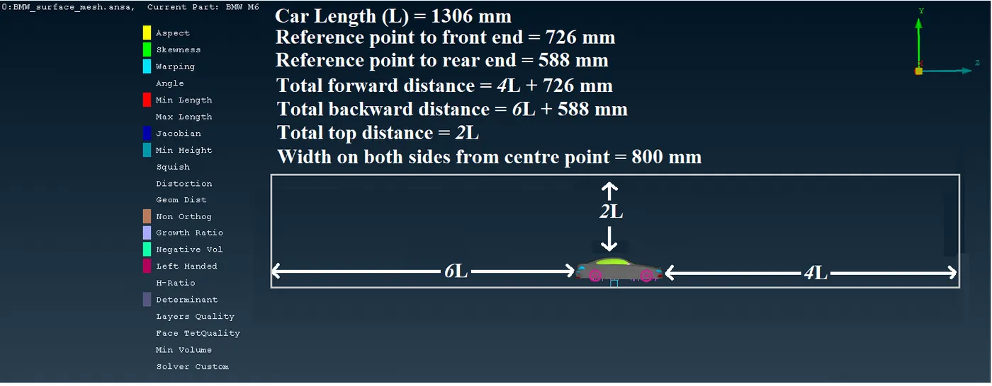
Once the dimensions of the tunnel are decided, from the reference point, few points are created at the prescribed length to create a plane; after that this plane is projected upwards with an offset of two times the length.
In the next stage the enclosure is made and another property IDs are assigned to the six faces as inlet, outlet, base, top surface and side walls.
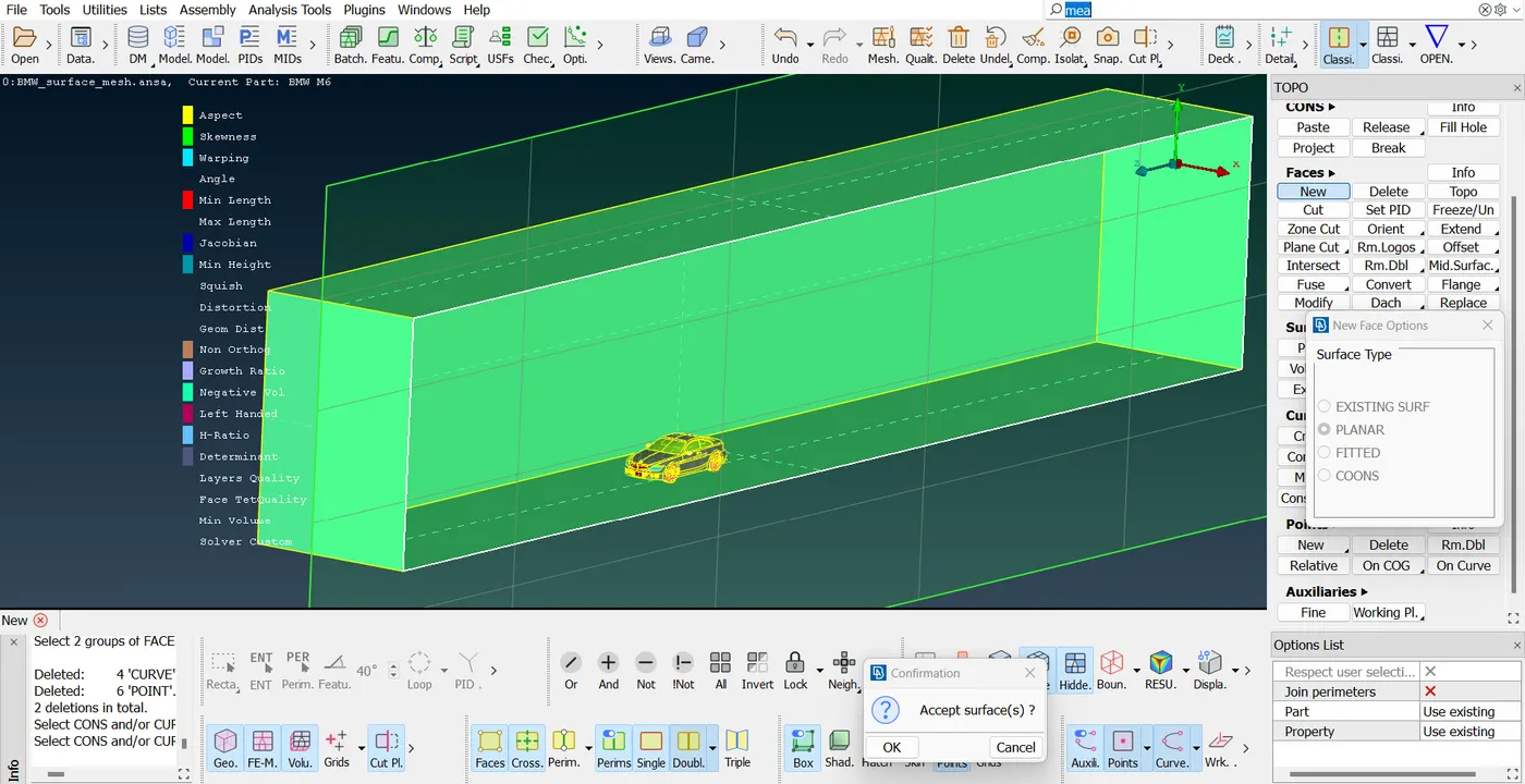
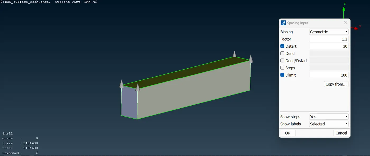
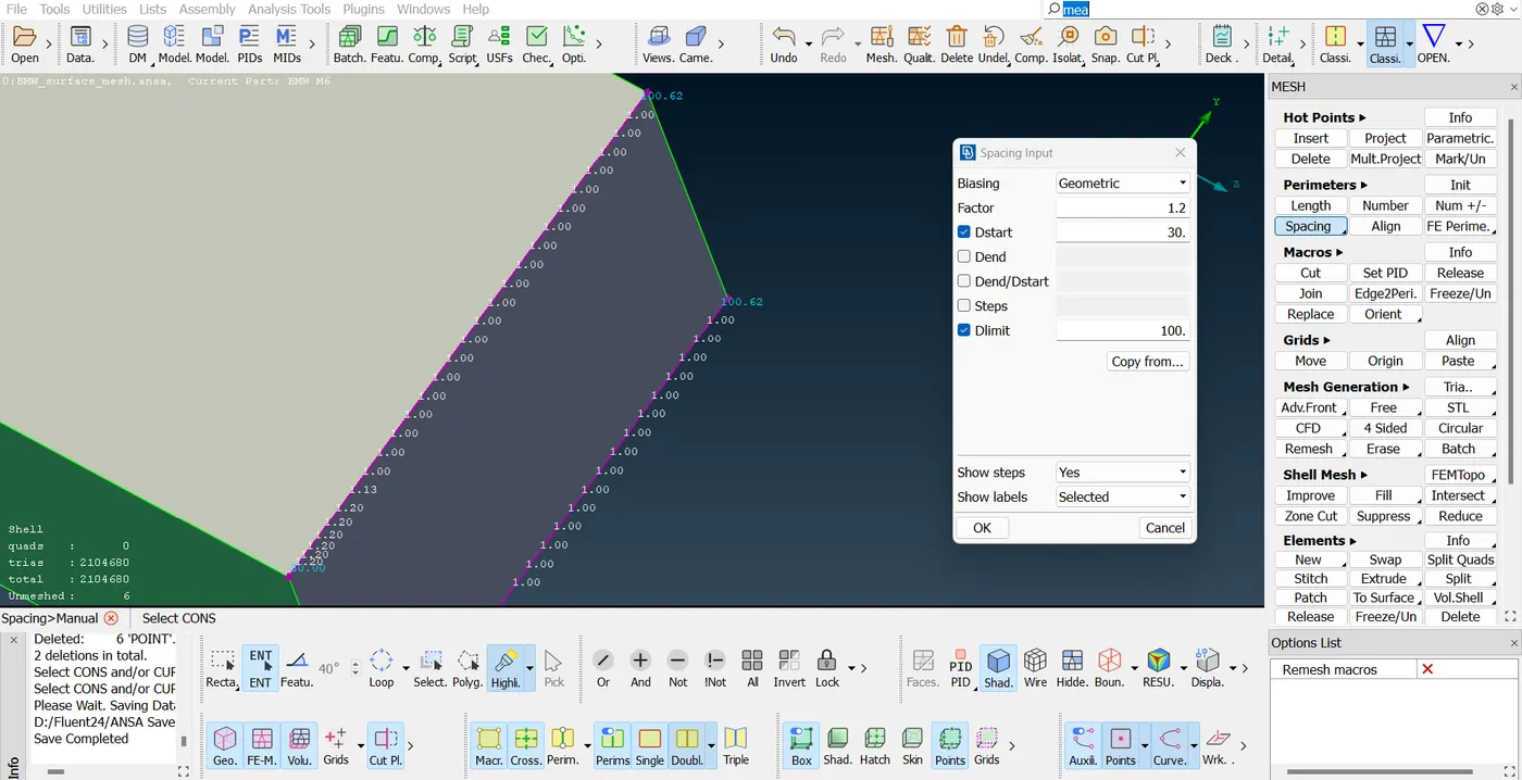
As the flow will be taking place On the surface of the car it is not required to have very much fine service in the Hole enclosure. Therefore a spacing is defined on vertextes of the inlet and outlet faces, such that the size of the cells will increase from 30 mm 100 mm on the top surface. After this the surface message created on the six surfaces.
To note that the minimum and maximum quality parameters for the cells are not defined on the side walls, inlet and outlet face.
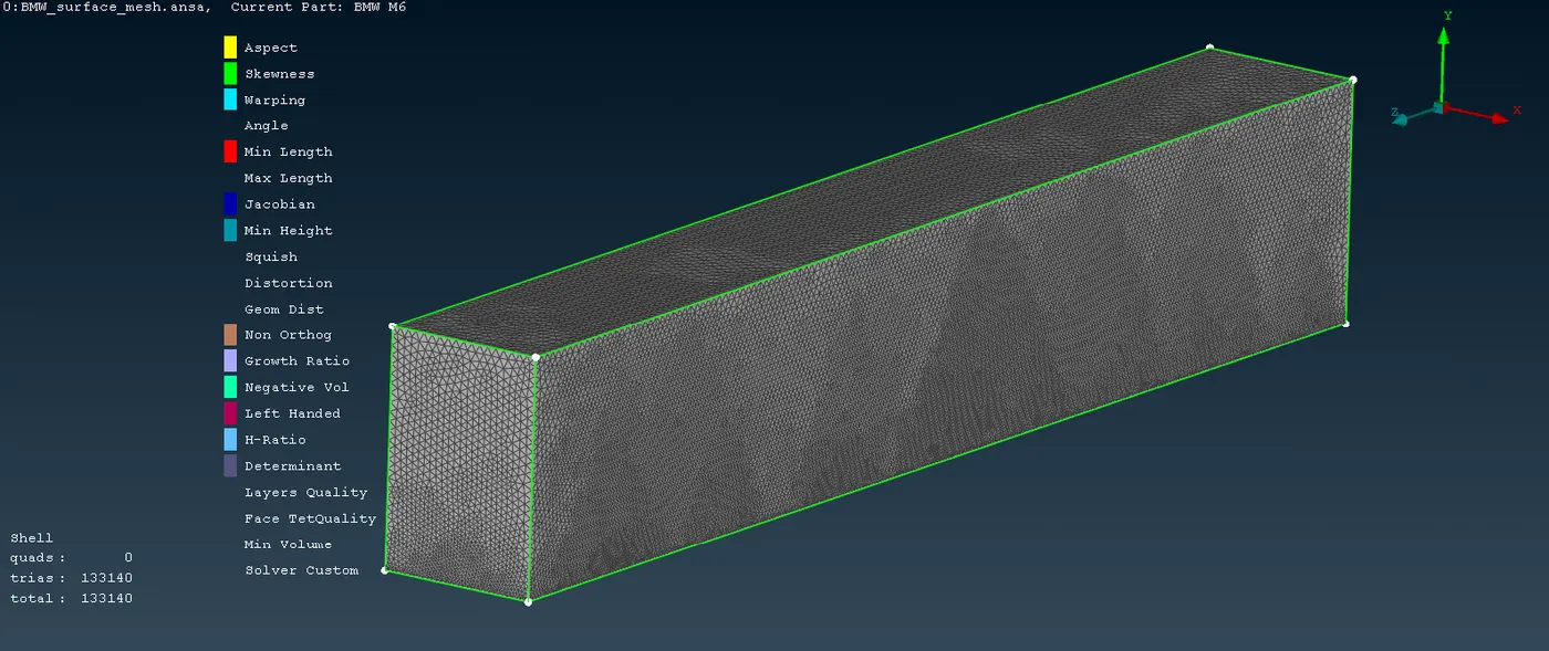
The total triangular faces on the enclosure are 133140.
Volume Mesh:
Now as the surface mesh is ready, the volume mesh can be performed. In the volume mesh section the volumes are detected as following.
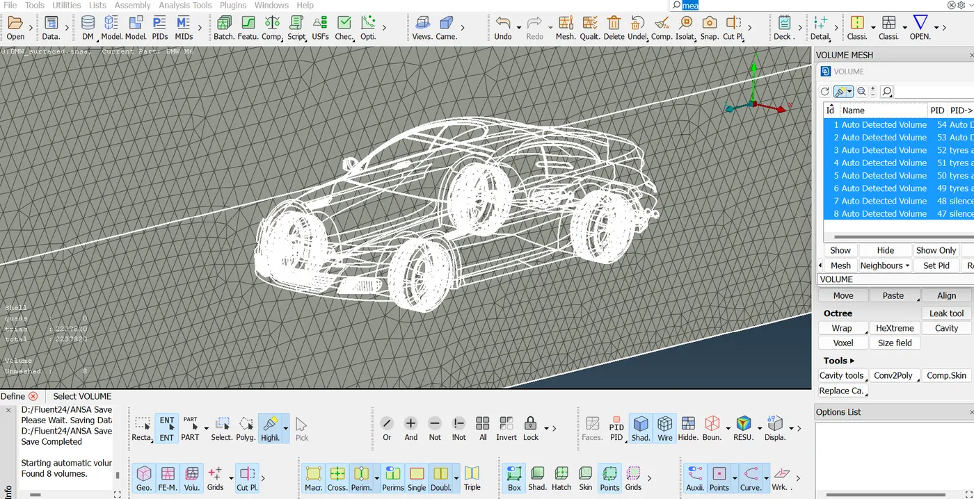
Amongst the all, the only volume of interest is the empty void space between the enclosure and the outer surface of the car, therefore the unnecessary volumes like volume of tyres, silencer, mirror, etc. are deleted.
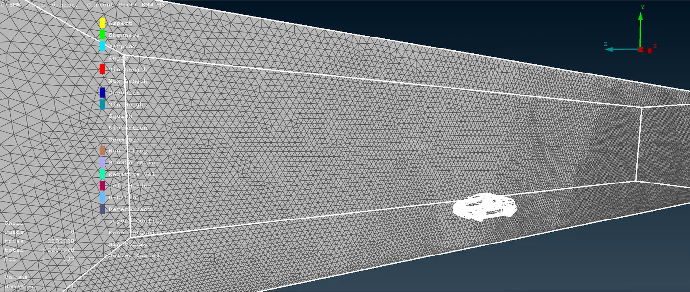
Later the volume mesh is performed in the void space using Tetrahedral elements.
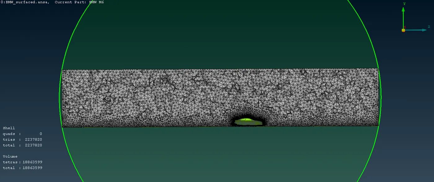
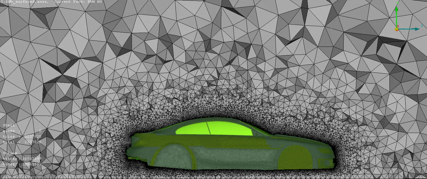
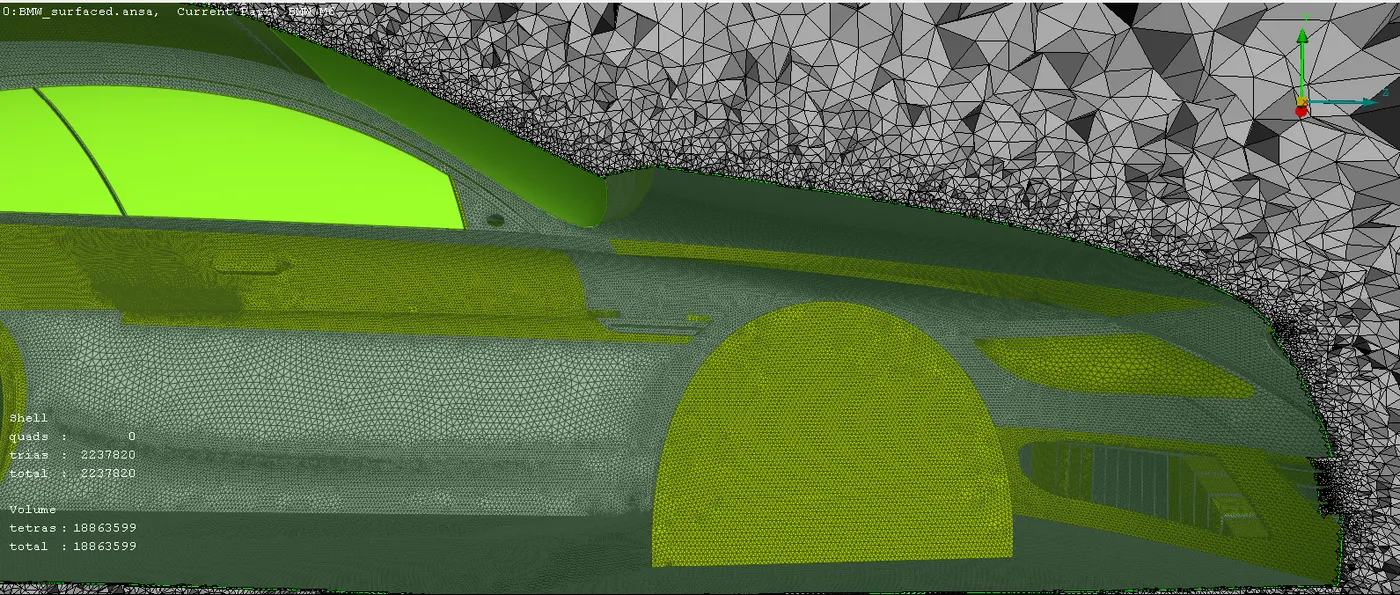
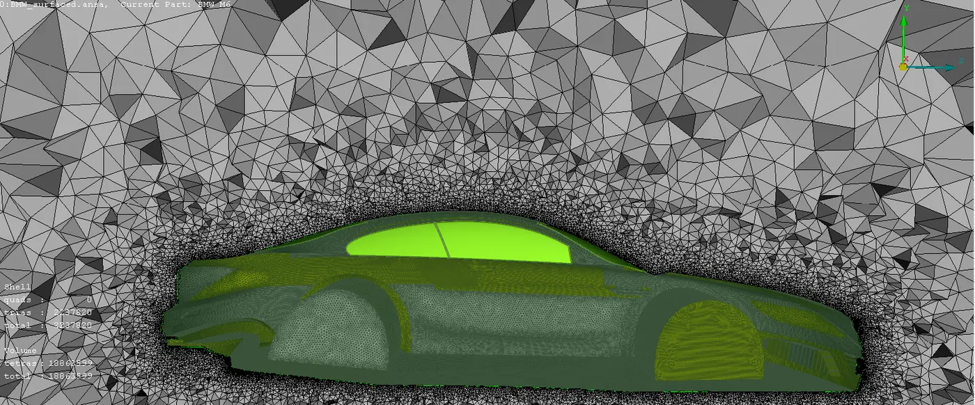
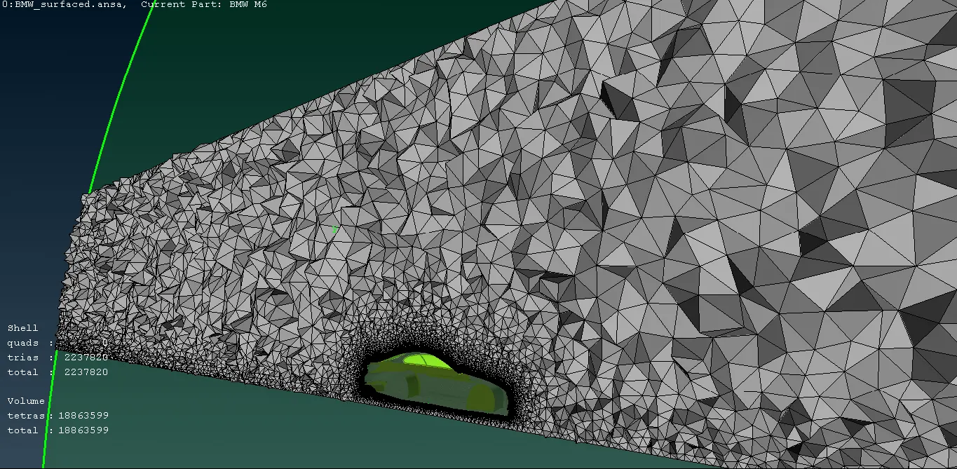
Once that is done the below picture shows the refined mesh on the near surface of the car which is visualized by creating a sectional plane.
The Total Cell count is approximately;
Shell Elements: 2237820 (Approx. 2 millions)
Solid Elements: 18863599 (Approx. 19 millions)
Furthermore, this model can be exported to the Fluent software to assign suitable boundary conditions and thereafter can be analyzed.