Week 4 Challenge : CFD Meshing for BMW car
CFD MESHING OF A BMW CAR USING ANSA
OBJECTIVE
-A detailed geometry cleanup of the model(BMW M6).
-Assign appropriate PIDs for meshing.
-Generate a surface mesh using the target length given below.
- Body - 3 mm
- Lights - 4 mm
- Grills - 1 mm
- Rims and Tyres - 2 mm
- Optical Rear view mirror - 2 mm
- Window - 2 mm
- Silencer - 3 mm
- Logo - 1 mm
-Analyze and correct the quality of the mesh.
-Set up a wind tunnel around the car;
PROCEDURE
As we saw above objectives, so we define the procedure in 5 parts
Part-1(Find the errors and clean up those errors in topo mode.
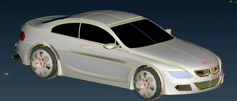
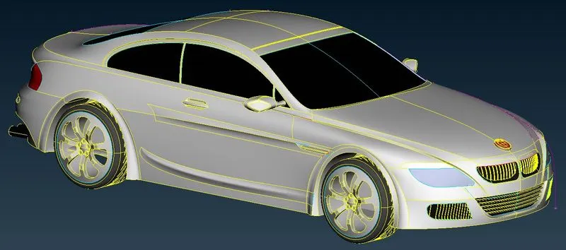
- As we saw, the model given below has some errors or looks coarse(30mm) so we reduced the mesh length to 1mm to fix the model.
Mesh length(30mm)
Mesh length of(1mm)
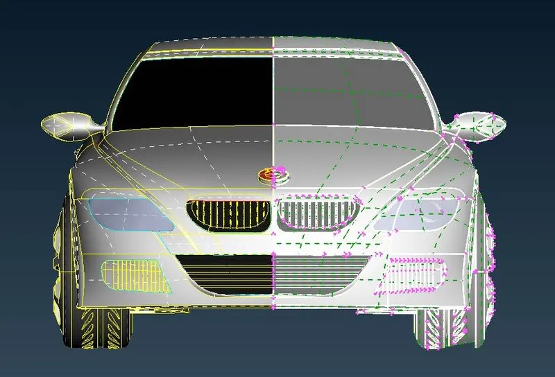
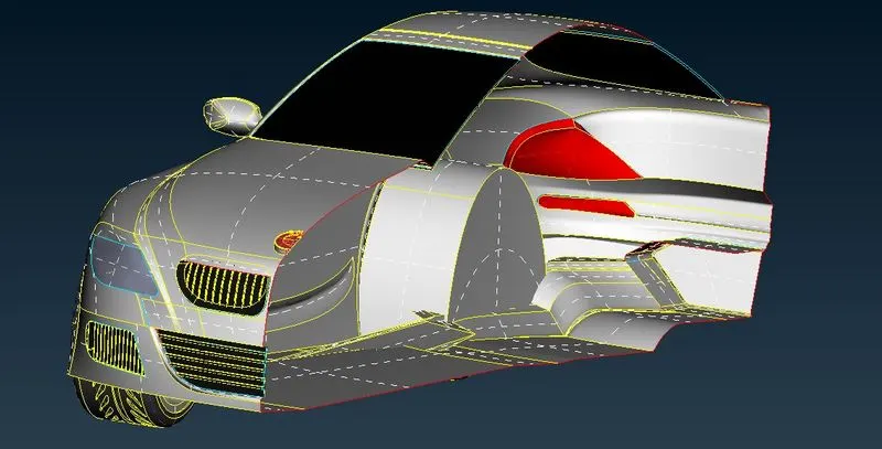
-After that, we cut the model from the middle as it is symmetry so that we can easily resolve our problem in our model and at the end, we can mirror it to the other side.
After cut
-We are now going for the topological clean-up part by part for a better view and is less time-consuming.
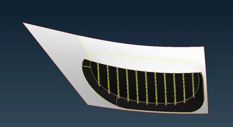
I-Grill Region
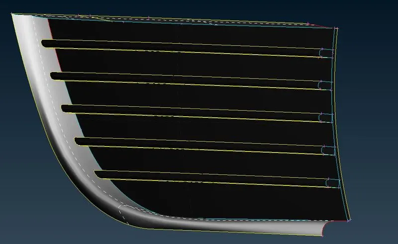
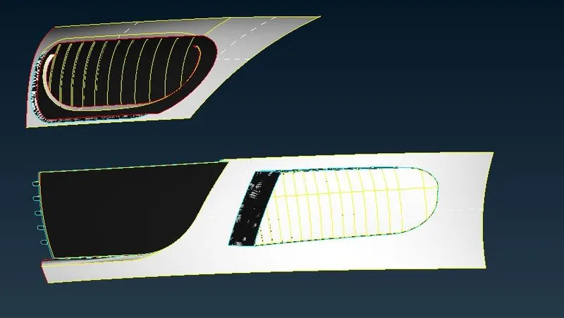
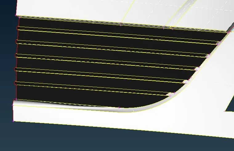
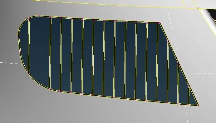
In the grill region, there are some overlapped surfaces and some triple cons that are tackled and deleted successfully because we perform the simulation on outer geometry hence the inner geometry is not required.
To remove and delete all the unwanted surfaces we used the Cut and delete tool.
-Errors are in the Grill region
-Refined or cleaned Geometry
II Light region
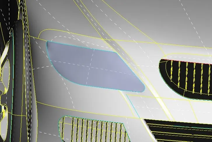
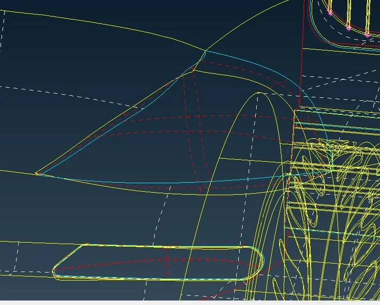
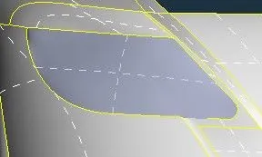
- As we discussed earlier we do not require the inner volume so we have to delete the unwanted surfaces from the headlight and backlight as well.
- In this region also some triple cons are present that are gradually solved as we deleted the unwanted surfaces.
Errors are in the light region
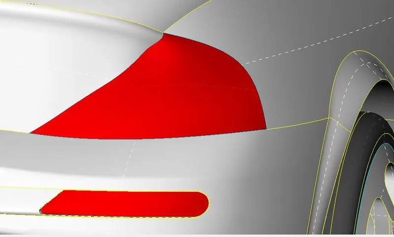
The refined or cleaned surface
III-Mirror region
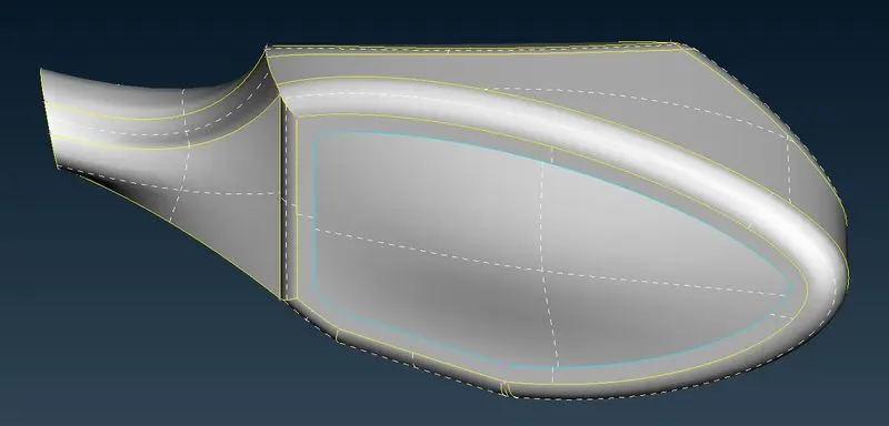
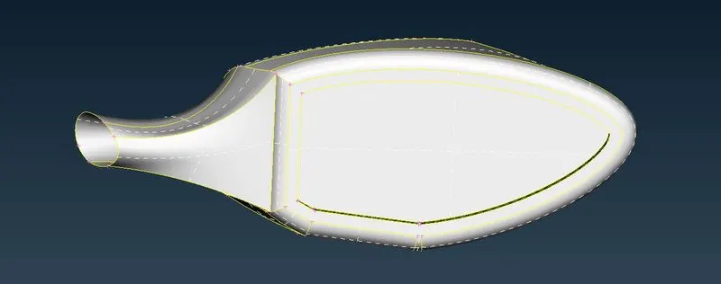
Here also we deleted the inner surfaces and create a Hollow region.
Error present in the Mirror region
Refined and clean surface
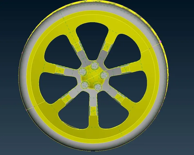
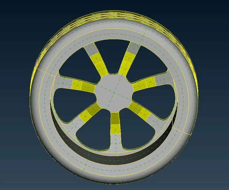
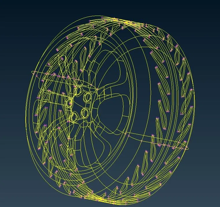
III-Tyres
-In this region some triple cons are present. to remove the triple cons, we deleted unnecessary surfaces inside the tyre region.
Errors are in the tyre region
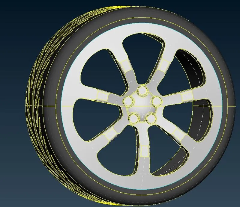
Refined surface
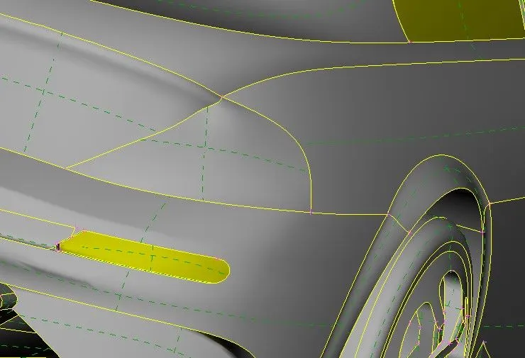
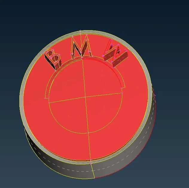
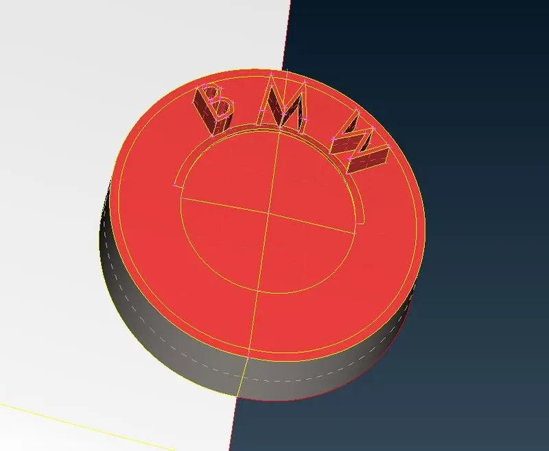
IV-The logo
In this region, we deleted the inner extra surfaces and created a hollow region and, we also did some changes to the upper BMW surface (cut some extra surfaces to remove triple cons).
Error in the surface
Refined surface
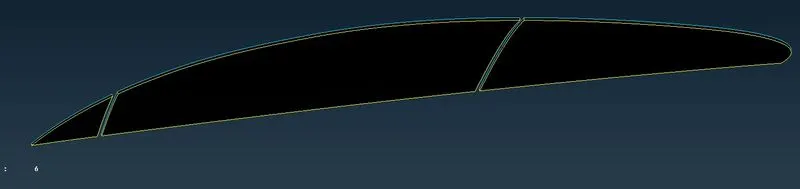
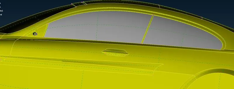
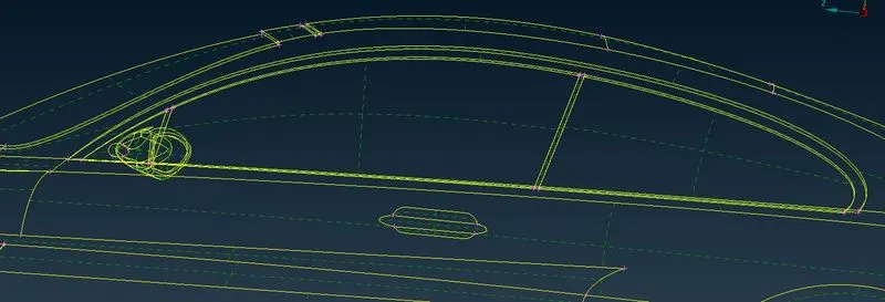
V-Window region
There are several triple cons present in this region due to the presence of the volume element instead of a surface element in this region. To fix this we deleted all extra surfaces.
Errors in the window region
Refined surface
VI- Base of the Car
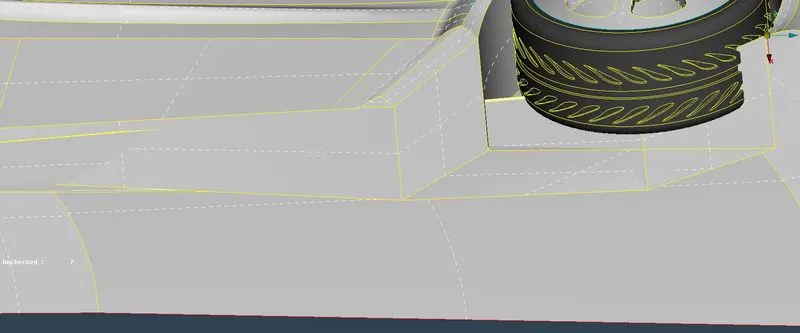
-In the base we have some extra intersect and sharp surfaces intersect the tyres so that we deleted and create a new region with a less sharp corner.
Errors present in Car base
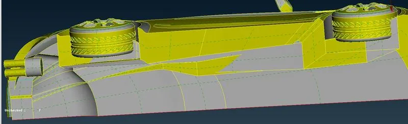
Refined base
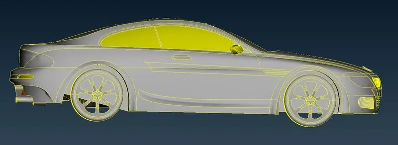
Part-2(Generating PIDs)
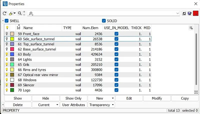
To Generate the PIDs of the model, we use the properties tab to list them.
Assigned PIDs Table
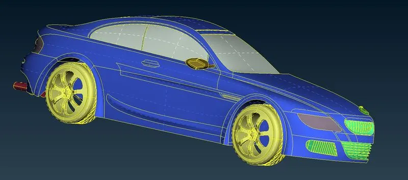
The car model after being assigned the PIDs
Part-3(Generating a surface mesh on the car body)
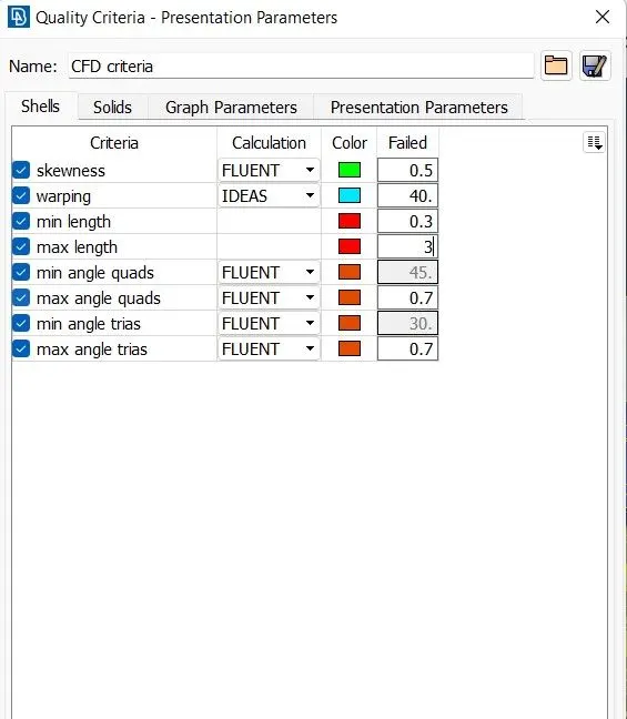
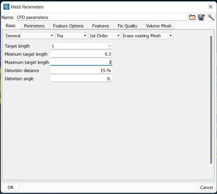
The mesh parameters, quality criteria and length are set according to different PID regions.
For meshing, we use the spot mesh tool and reconstruct the mesh if any off elements are there.
Mesh parameter and quality criteria
Target length
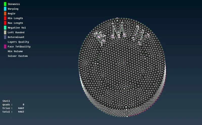
- Body - 3 mm
- Lights - 4 mm
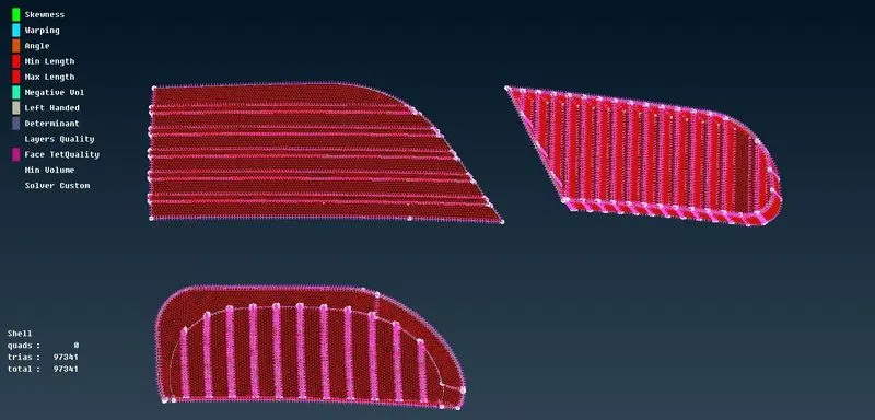
- Grills - 1 mm
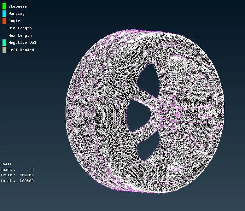
- Rims and Tyres - 2 mm
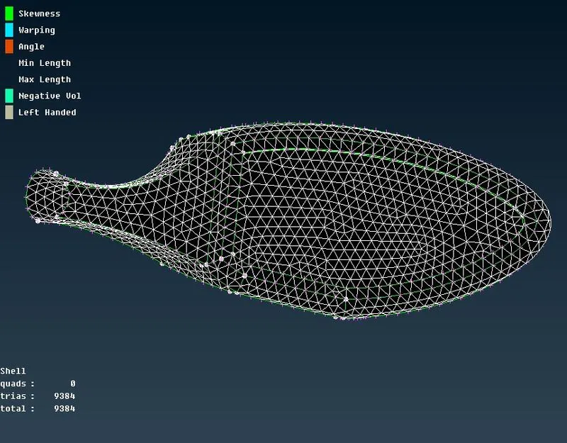
- Optical Rear view mirror - 2 mm
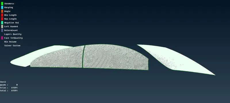
- Window - 2 mm
- Silencer - 3 mm
- Logo - 1 mm
Surface meshing
Due to different target lengths given for meshing, that's why we mesh the components individually.
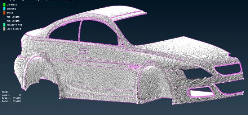
In the body, the PID region is in contact with other PIDs so that the mesh length variation at the boundary region of 2 different pids causes the mesh to erase or cause mesh failure in that particular region. Therefore, while entering the perimeter under a length in the mesh. select the region which is not in contact with other PID regions. This helps in avoiding the mesh being erased and can later be edited to erased and can later be edited to erase the off elements.
I-Logo
II-Grills
III- Rims and Tyres
IV-Rear View Mirror
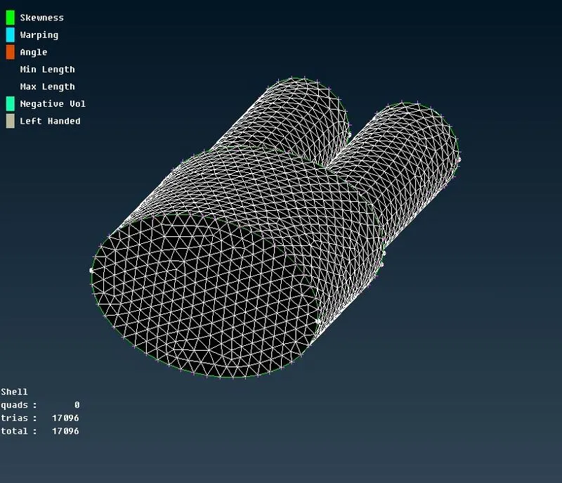
V-Silencer
VI-Body mesh
VII-Windows mesh
Part-4(Generating or joining the other half)
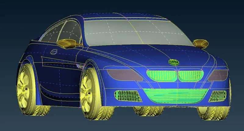
As we discussed above this is a symmetry model so we have a tool called transform where we can copy, move and link the model as per required.
But for this model, we 1st use the copy option and then chose three points to join the other half n execute.
The whole car model
Part-5(Creating the wind tunnel and volumetric mesh of the wind tunnel)
Dimension of the wind tunnel
Car length-1300 approx so,
- From the Front of the car is 4x that is 5975mm
- From the Rear of the car is 6x that is 8680mm
- From the Top of the car is 3x that is 4323mm
- from the bottom is 75mm
- From the centre plane -the left and right are 1x which is 1300mm
Wind tunnel
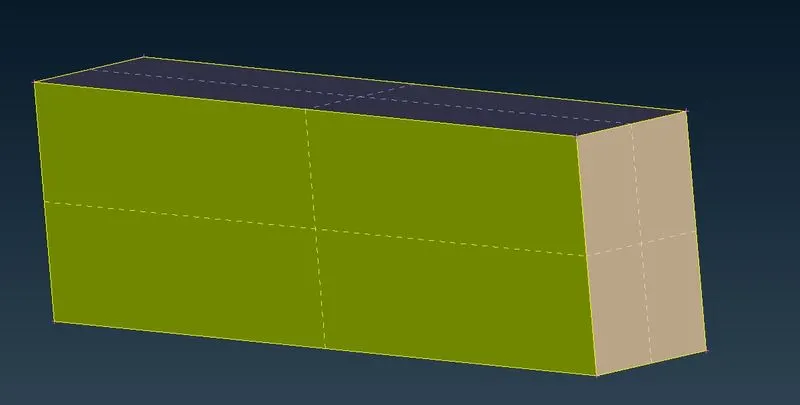
The meshing of the wind tunnel
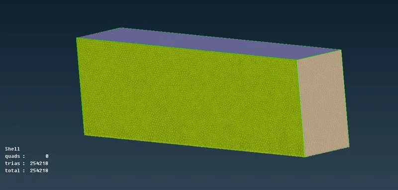
A geometry spacing is a creat with a factor of 1.1, with the smaller mesh elements increasing from the bottom to the top. This is because the top of the wind tunnel is less important compared to the bottom. finally, the wind tunnel has meshed.
since performing volumetric mesh required 2-3 days so we did not perform it.
CONCLUSION
All 5 parts are concluded successfully, we get a cleaned and improved mesh and the wind tunnel is set up successfully.
BMW M6 MODEK FILE
https://drive.google.com/file/d/104SeSrEqWZqFHxzzq7oycommxFgtY_SH/view?usp=sharing