Week 4 Challenge : CFD Meshing for BMW car
REPORT:
Aim: To Perform surface mesh and Volumetric mesh.
Objective:
- Perform surface mesh with the given target lengths as per PIDs.
- Body - 3 mm
- Lights - 4 mm
- Grills - 1 mm
- Rims and Tyres - 2 mm
- Optical Rear view mirror - 2 mm
- Window - 2 mm
- Silencer - 3 mm
- Logo - 1 mm
Procedure:
1. Geometry topo cleanup and PID Creation:
- The geometry is imported to ANSA software.
- understood the geometry.
- car model looks symmetric as then it divided longitudinally into two parts except logo and deleted one side.
- check the errors and over lapping faces.
- isolated each parts and cleared the errors and deleted over lapped faces.
- created car model as one volume except rims and tyres, silencer.
- closed the geometry by deleting and creating new faces.
- isolated each parts using 'not' command to assign PID's using PID manager as follow
- body
- lights
- grills
- windows
- optical rearview mirror
- logo
- silencer
- tyres and rims
2. Surface Meshing:
- to create surface mesh on each PID.
- lets consider the PID logo to create surface mesh.
- logo is assigned using Not(PID) option or also can be isolated from PID manager as well.
- opened mesh quality criteria and entered the value of min length (i.e. 0.4 mm) and max length (i.e. 2 mm).
- opened mesh parameters and enter targhet length (i.e. 1 mm) and also min and max target length value.
- selected element type as tria.
- from perimeters menu selected length and assign perimeters and macros to logo PID.
- then created spot mesh on isolated PID.
- followed the same procedure from every PIDs except body PID.
- for meshing body PID, from perimeter menu selected length and assign only perimeters on only cons other than cons which are common with another PID to avoid mesh loss of other PID.
- then generated spot mesh on body PID with required target length.
- Target lengths, min target length and max target length for each PID is shown below.
-
Sl.No. PID's Target length min length max length 1 logo 1 0.4 2 2 grills 1 0.3 2 3 windows 2 1 3 4 lights 4 3 5 5 silencer 3 1 5 6 optical rearview mirror 2 1 3 7 tyres and rims 2 1 3 8 body 3 1 5
3. Creating wind tunnel:
- for creating wind tunnel, one point is reffered at the middle of bottom surface and plotted one point exactly downwards at a distance of 60 mm using relative point option from the reffered point.
- suppose length of car is x mm which is =~1300 mm for the provided car model.
- we need to plot one point from front side of car at distance of 4x from most front point of car.
- the most front point of car model is at distance of 770 mmand the most rear point of car model is at distance of 530 mm from newly plotted reffered point.
- so the front point will be at (5200+770)= 5970 mm distance from reffered point.
- we need to plot one point from rear side of car at distance of 6x from most rear point of car.
- so the rear point will be at (7800+530)= 8330 mm distance from reffered point.
- then plotted points on both the sides of both rear and front point at a distamnc of (1x) 1300 mm.
- created curve to join all the four corner points(straight lines) to create surface.
- then surface is created below the car model.
- then extra points and curves are deleted from that surface by hiding car madel and below surface.
- the same surface is copied straight above the car at a distance of 4273 mm ( 3x + height of car model).
- then surface is created using fitted from new faces from all the sides of car model reffering those two surfaces.
- then created PIDs as
- basesurface_tunnel
- topsurface_tunnel
- frontsurface_tunnel
- rearsurface_tunnel
- sidesurface_tunnel
- and then assigned PIDs to each side.
- then mesh base surface with target length = 20 mm, min length= 15 mm, max length= 25mm and top surface with target length = 100 mm, min length= 80 mm, max length= 120 mm by the same procedure used for logo PID.
- Then used spacing command for side, front, rear side PIds and assigned spacing from bottom to top from 20 mm to 100 mm with factor of 1.1.
- then generated spot mesh on every PID one by one.
3. Volumetric Meshing:
- selected volume mesh deck.
- In that selected 'define' command from volume deck and selected detect on as on whole data base.
- got automatically generated volumes.
- from that volumes, deleted unwanted volumes which are not supposed to be meshed. and keep only one volume which is between car model and tunnel.
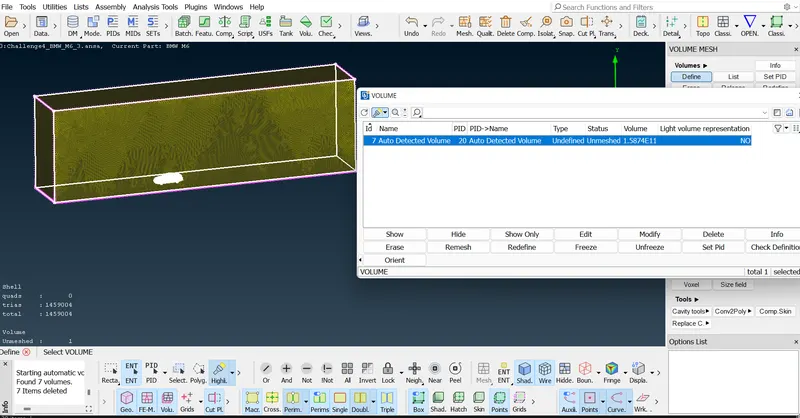
- then we should use 'Tetra CFD' type mesh on required volume.
Results and conclusion: model is well studied and understood, PID's are assigned. surface mesh is done with required target lengths. volumetric mesh is carried on required volumes.