Week 4 Challenge : CFD Meshing for BMW car
AIM:
To check and solve all geometrical errors for the given BMW car model and generate meshing for the same.
OBJECTIVE:
- Check and solve all geometrical errors on halfportion of the car and simplify the componenet down to single volumes
- Assign appropriatesPID`s to the individual component of the car
- Perform meshing with the given target length and element quality criteria.Target length for the different parts of a model
- After meshing the half model, do symmetry to the other side and make sure the model clears the quality criteria .
- Build a wind tunnel volume around the car geometry and generate surface meshing for the windtunnel surfaces.Write adetailed report for the same
PROCDURE:
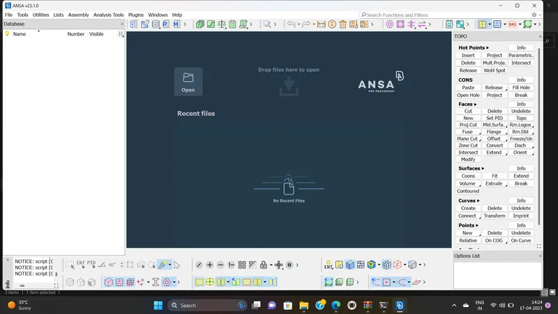
The first open the ANSA CFD software open a fresh page and start the resolve the errors.
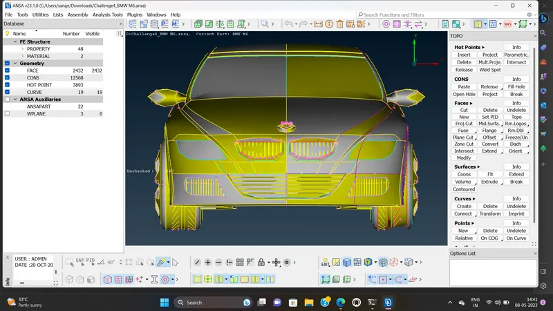
The first and foremost step in the process is importing the BMW car geometry into ANSA.The imported geometry is as shown.
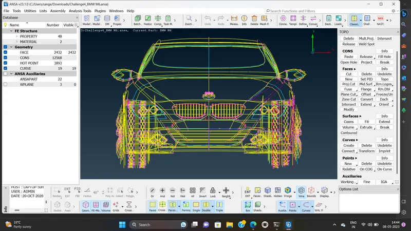
BY turning on the WIREFORM MODE , we can observe that there are various errors and overlapping surfaces in the entire geometry.
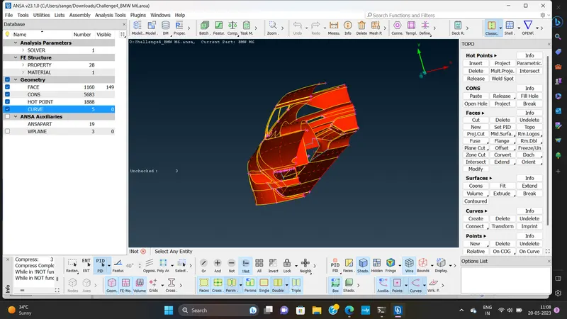
In order to identify these errors,we first run a geometry check.The various errors and warningsare identified as shown.
TOPO CLEANER:
In order to resolve the errors in the geometry, we need to perform topo cleanup.First,we fine the resolution of the geometry so as to capture the componenet in much more details.we do this by reducing the perimeter and macros length for the whole geometry.
BEFORE:
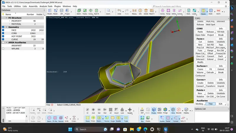
AFTER:
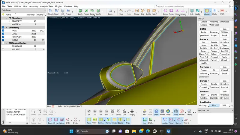
BEFORE:
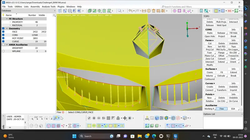
AFTER:
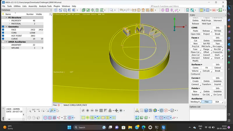
The geometry of the car is AXISYMMETRY in nature .therby,instead of resolving all the errors across the entire geometry,wecut the geometry in half ,solve the errors on that side of the geometry and then we mirror it.
The CUT-SECTION of the geometry is as shown.
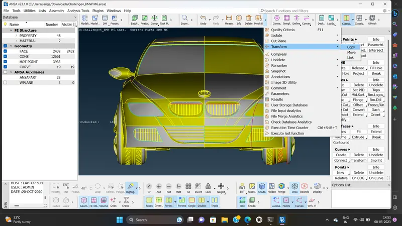
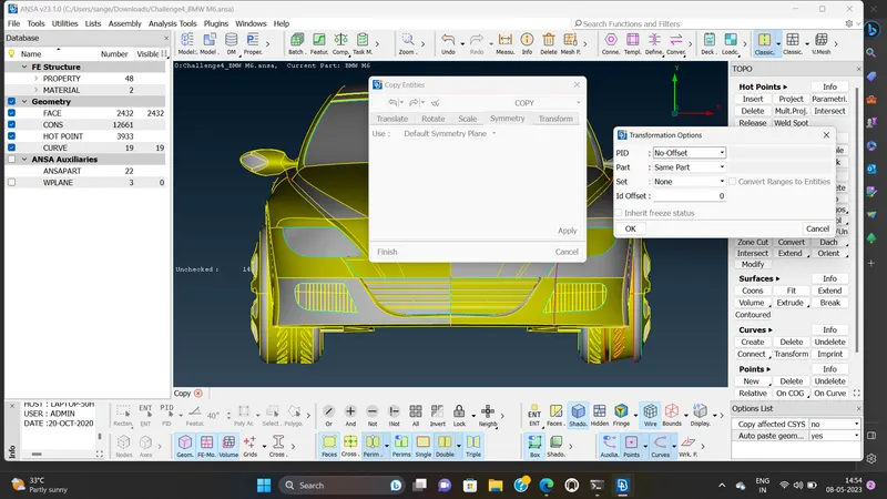
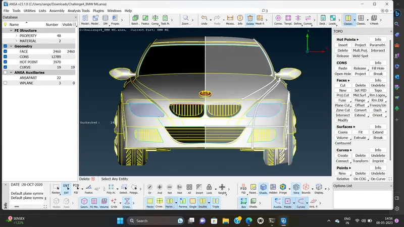
TRANSFORM option>>ENTITIES>>SYMMETRY option .
For deleting the left side centerly conc BMW disselect>> PID`s region.
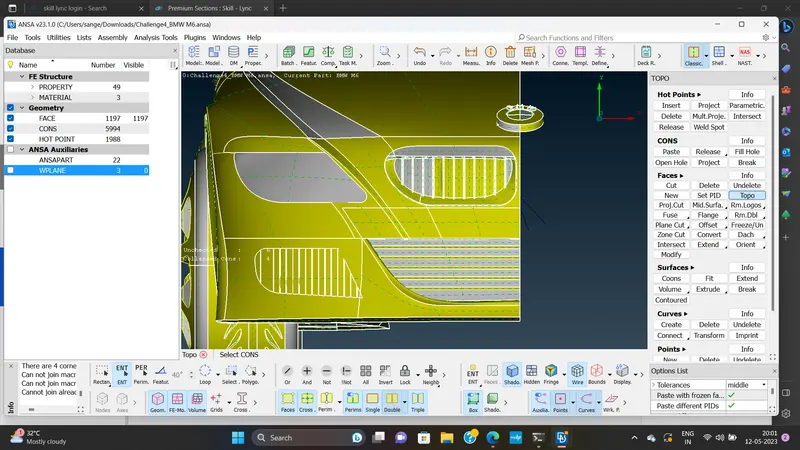
Now see half part is deleted .Before starting this model ,AJENDA.
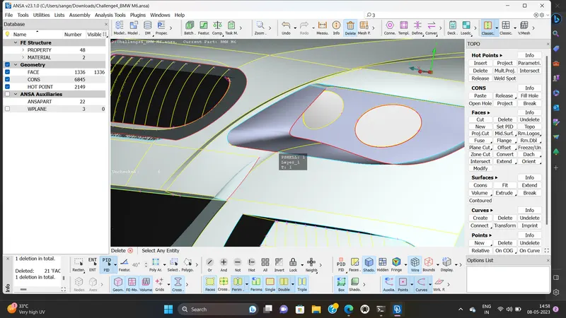
Try to delete the unnecessary surface the inside and outer surface will to it,will do the same.
I will go their delete the insidesurface,Inorder to delete that .I can you selection view.
Also explore the PID`s region .It see it working now.
GRILLS:
We are first going to solve teh various errors in the grills of the car.we name these grill as lower - mid grill ,lower left grill and upper grill with reference to their location and we solve them individually.
a]LOWER GRILL:
From the below video we can be observe that there are various overlapped surface and uneven connections in the geometry.
The main objective here is to solve all these errors as well as make the entire grill as a single geometry.
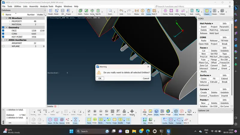
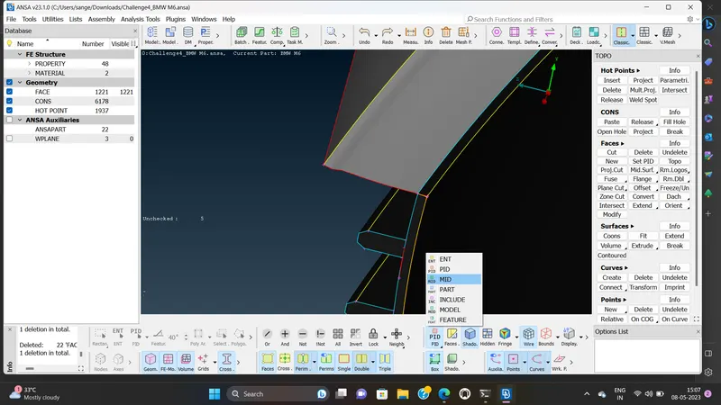
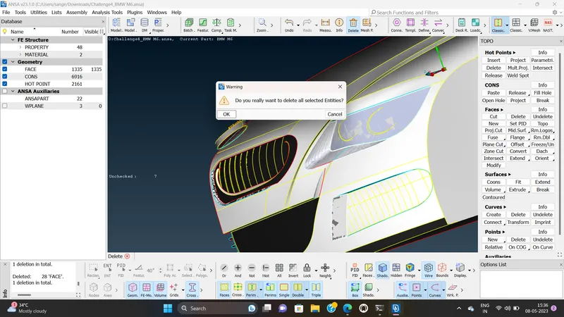
Alignment of the grills with respect to the back surface.We do this by projecting the conc onthe back surface which the grills are connected .
next ,we form new surfaces with respect to the newly formed CONC as well as deleting the overlapping surgface surfaces.Thereby,the grills are aligned to the surface as shown.
b]LOWER LEFT GRILL:
By isolating the grill and observing it from different views,we can see thst there various overlapped surface and error in the component .
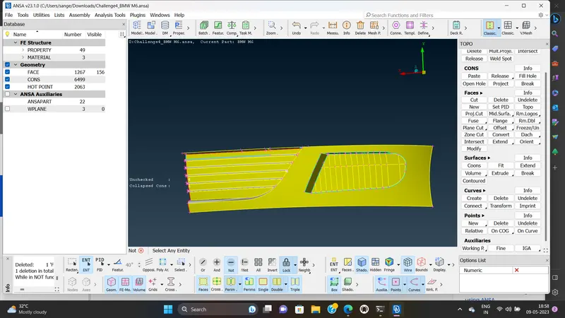
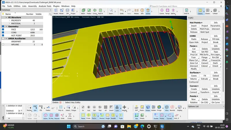
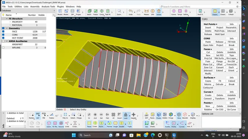
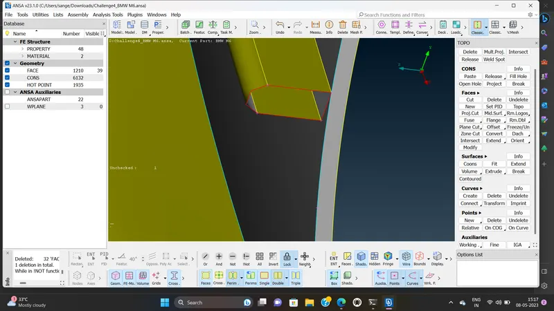
First,we delete the overlapped surface on the sides of the grill.The unaligned grills at the rear end of the geometry are solved by removing a small section of the geometry at the back end and creating a new surface covering those edges.
The section behind the new formed surface is deleting and therby,aligning the grills .
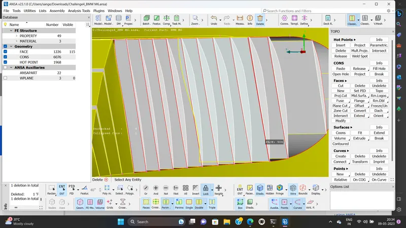
Finally,we delete the intersecting surface and the extra surface around the grills, therby making the geometry as a single volume and resloving all the triple conc.
c]UPPER MID GRILL:
we first isolate the grill and the surfaces connected to it, so as to visualize the errors more precisely.
Finally ,we delete the upper part of the grill and create new faces to connect all the remaining surfaces together such that we obtain our FINAL GEOMATRY which is free of errors, as follow.
LOGO:
in thid part ,we are going clear the various errors related to the logo.we can observe that ther are various overlapping surfaces.
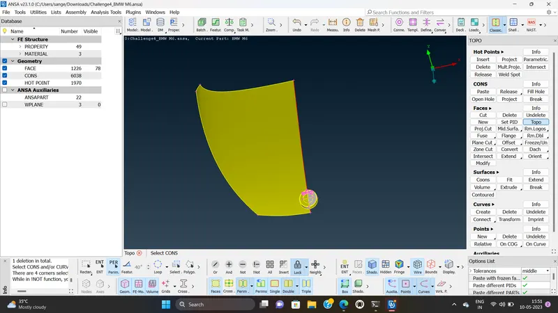
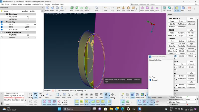
In order to solve this, we first delete the overlapping surface by projecting the conc on the hood surface.Also ,we delete the extra surface logo a single volume.
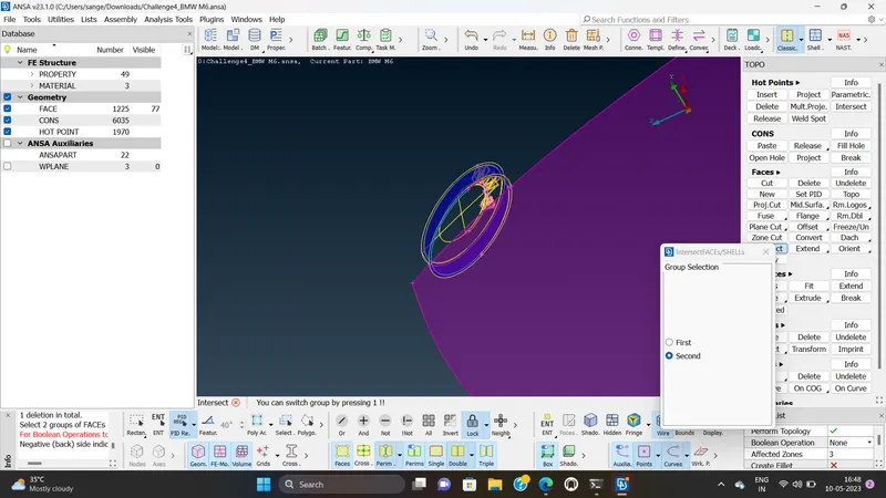
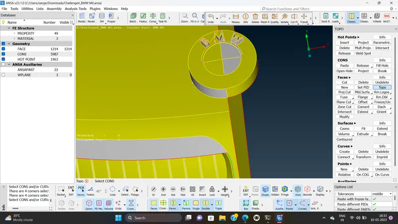
Finally , we solve the single conc around the logo by creating new surface and therby, the final geometry is obtained as follow.
LIGHT:
The below geometry represent the front and rear lights of the cars.
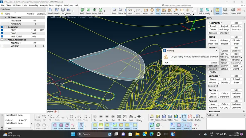
First, we are going to solve the triple conc by deleting the overlapping surface as well as the additional surfaces.thereby , the geometry are simplified as shown.
OPTICAL REAR - VIEW MIRROR:
The rear view mirror is attached to the side window and consists of triple conc and overlapped surfaces as shown'
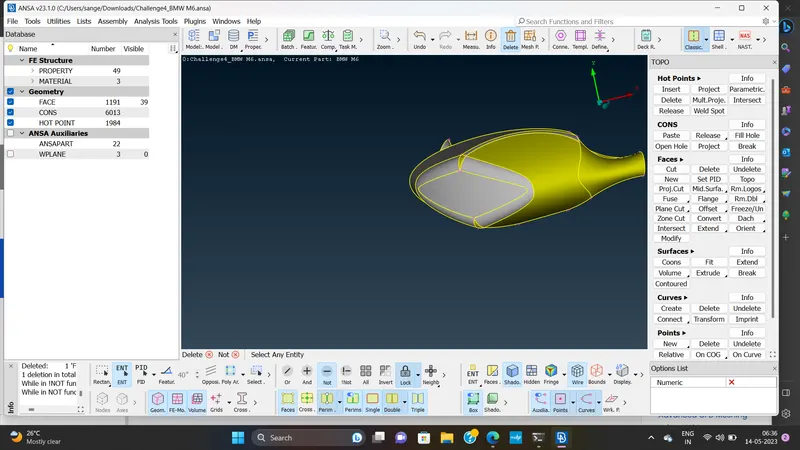
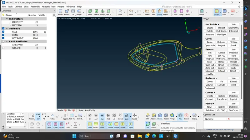
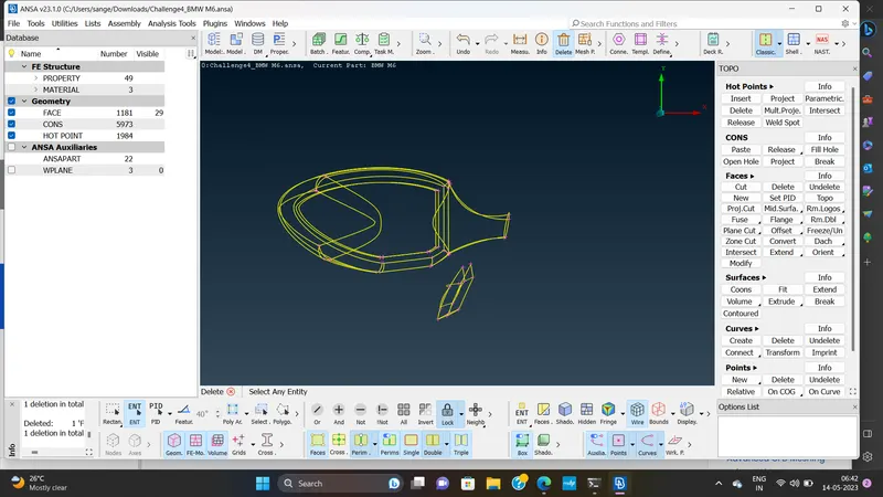
we solve the triple cons by deleting the extra surface.In order to make the mirror a single volume.
we remove the overlapping part from the side window the final geometry is as shown.
This part of the geometry contain triple cons aroundthe surface of the rims,caused due to the overlapof surface.
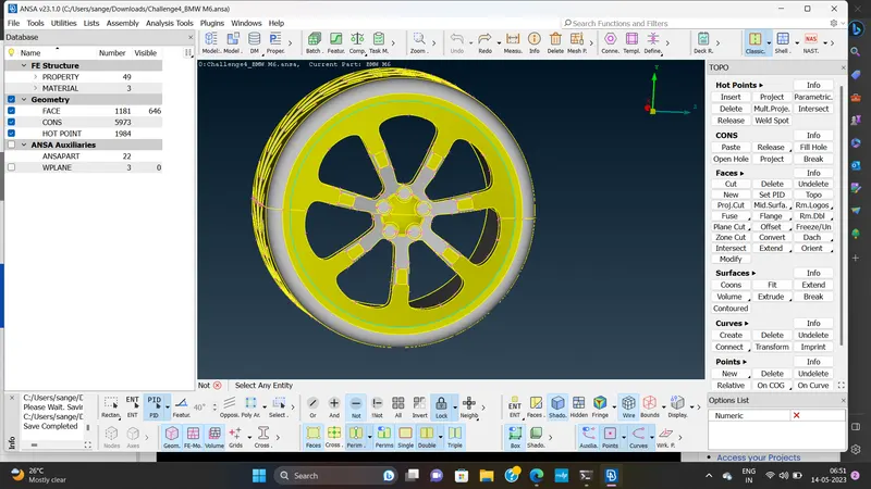
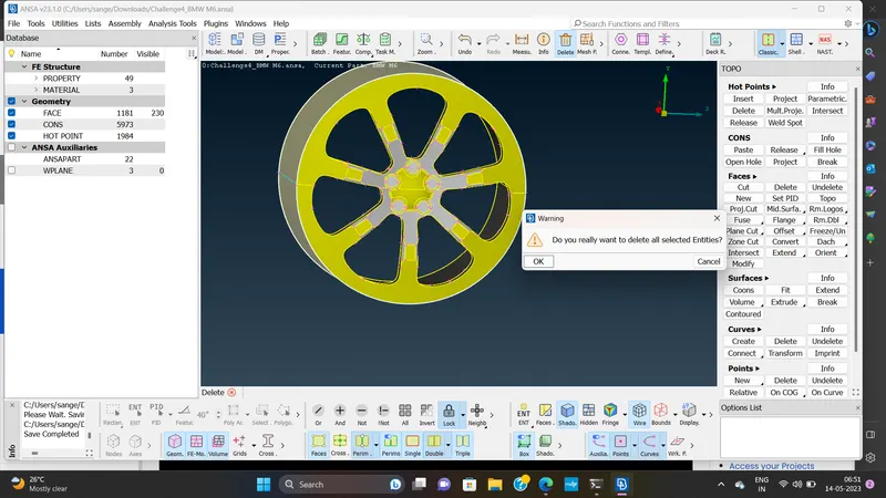
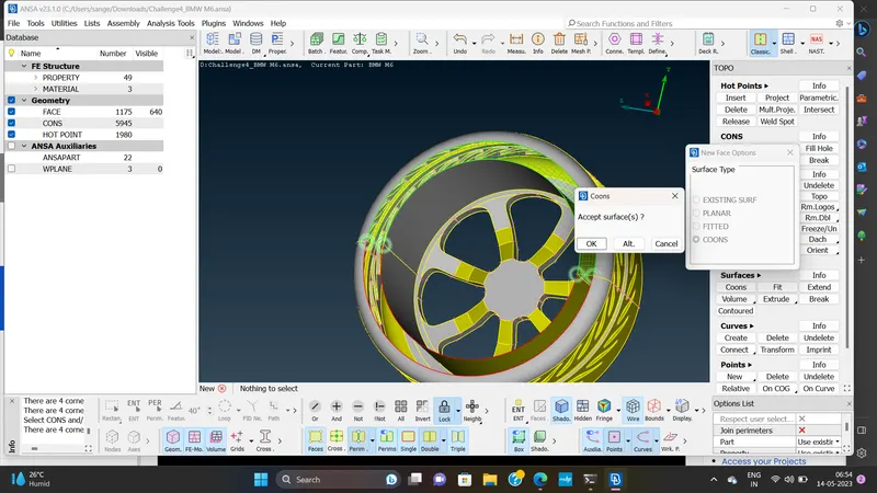
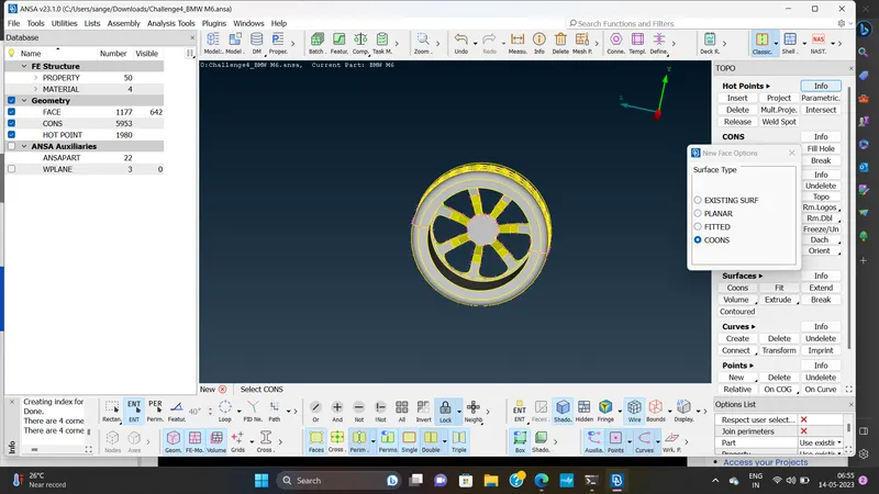
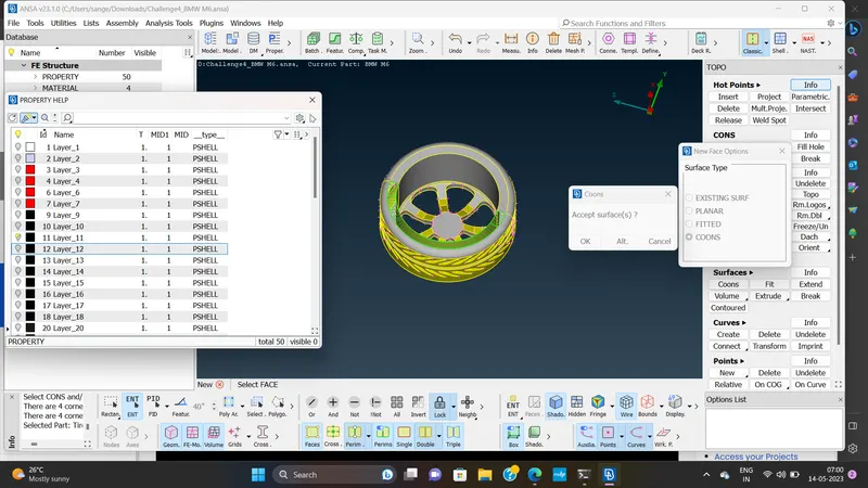
we simply resolve itby deleting those extresurface and forming new surface overthe missing faces as follows.
we repeat the same procedure for both the wheel.
MESHING:
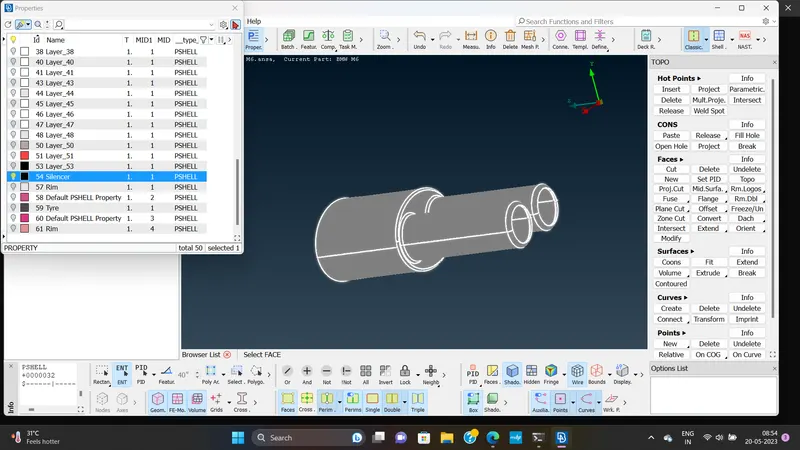
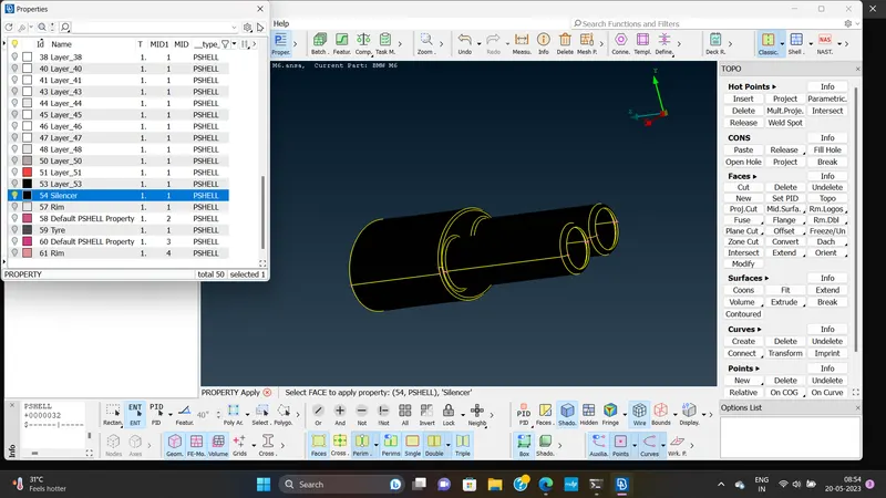
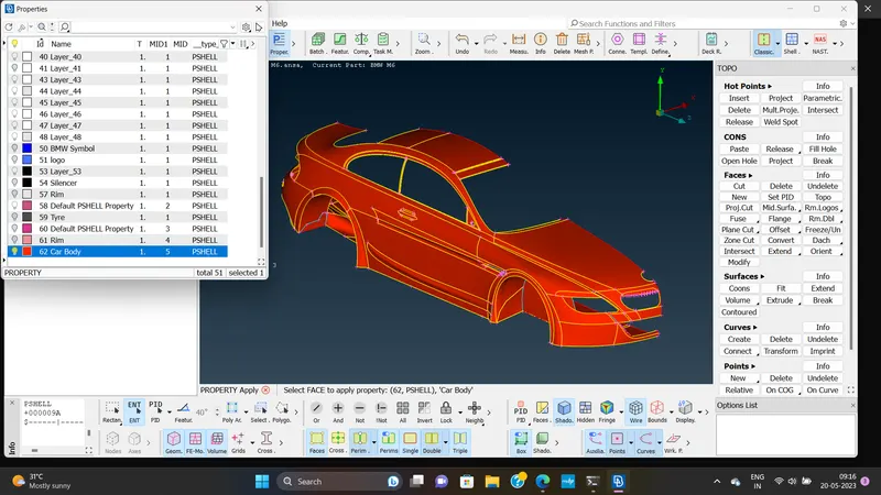
The next step in the process after assigning the PID`s is meshing the half part of the geometry.
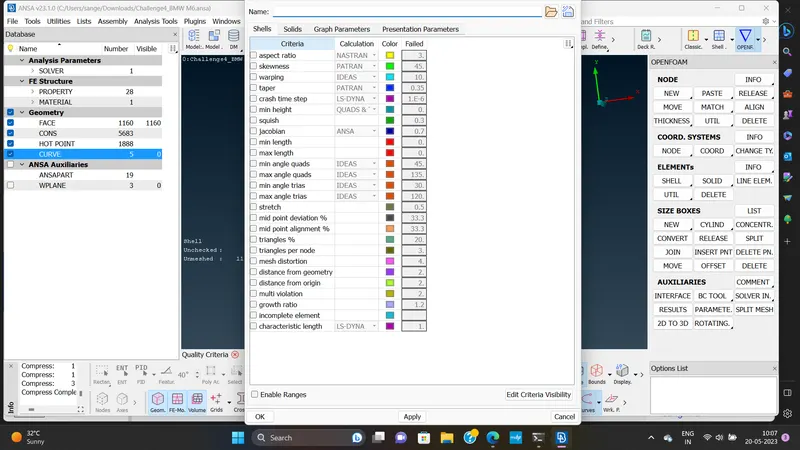
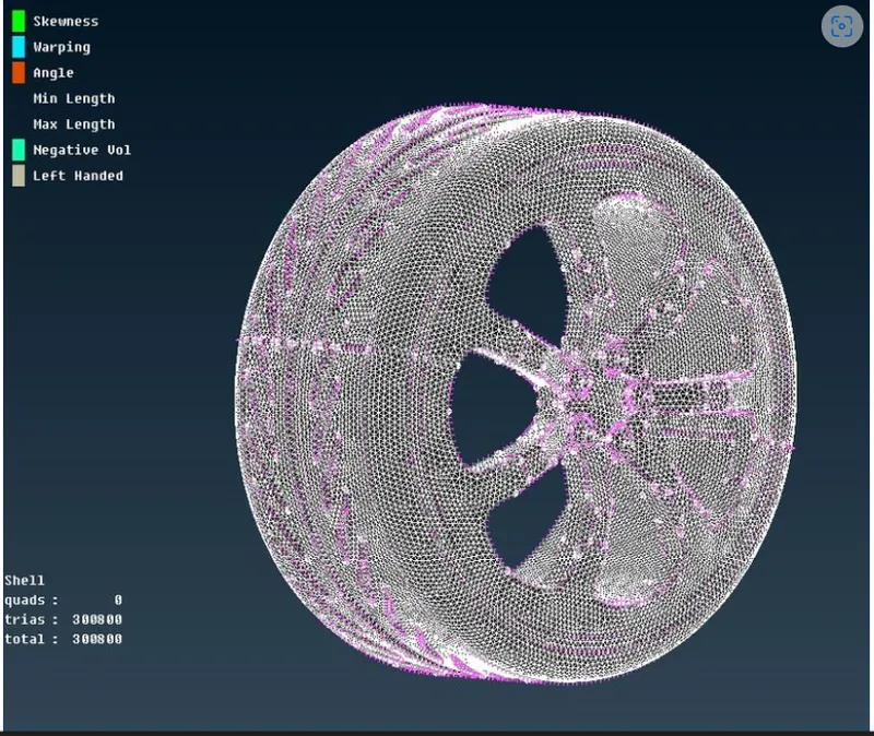
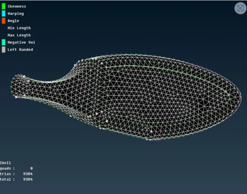
we mesh each individual components in accordance to the target length provided in the problem.
BODY=3mm
LIGHTS=4mm
GRILLS=1mm
RIM AND TYRE=2mm
WINDOW=2mm
SILENCER=3mm
LOGO=1mm
MIRRORING:
After obtaining the mesh for the half part of the geometry and clearing all the off the element as well as ,we then move on to mirroring that part of the geometry so as mirroring that part of the geometry so axs to obtain the the entire geometry.
along with the geometry ,the meshing is mirroresd as well .
WIND TUNNEL CREATION:
WIND TUNNEL tests help us better understand the nature of flow of air and around a vehicle or object.
The charactertisticof the flow around the bject canalso be visualized using a number techniques-smoke injection and oil flow on the test article to name a few-meant ti''make the invisible air visible .
Also the aerodynamicforces acting on the object,such as drag and lift can be measured by accurate load measuring devices.
Now, we use the create new curves connecting the nodes and we thereby create the bottom face and assign the respective PID`s it.
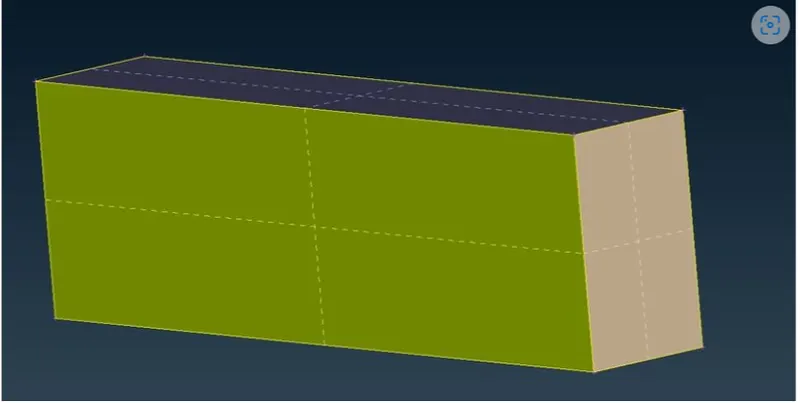
For thenside face ,we generate a growing mesh,growing upward from the bottom face up to the top face.
The element size start from 20mm and grows to a size 0f 100mm as it move forward.
we generate the growing mesh by using the manual spacing option, with the start point being 20mm and end point being 100mm
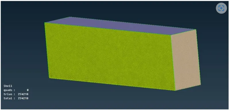
Thereby , the final wind tunnel geometry is obtained as follows.