Week 4 Challenge : CFD Meshing for BMW car
ANSA is an industry-leading pre-processor software widely used in automotive industries.
It is used to pre-process the geometry before a CFD or FEM analysis.
INTRODUCTION:
The aim of the project is to clean up the BMW M6 car model by removing its topological errors. Further defining the different property ID\'s and also making the model browser easier to access. And the main part is meshing the whole model by specifying the mesh parameters and defining the quality criteria of the mesh to be generated. The mesh elements which are deviated from the defined criteria are to be rectified. And the final part is that creating the wind tunnel suitable for CFD analysis of the car model which is an external airflow analysis.
1. Geometry Clean-up:
While importing the part model to ANSA there will be a lot of topological errors such as cracks, unwanted holes, missing entities, unwanted surfaces, modeling errors, single cons, triple cons, etc. All these should be rectified before meshing the model for analysis.So the model is imported to ANSA. The view is changed to PID mode along with a shadow mode with all the cons visible.
- We will only work on the left side of the car and then simply use the symmetry option to mirror the complete geometry of the left side to the right side of the car. in this way we can save a lot of time. So, delete the right half of the car.
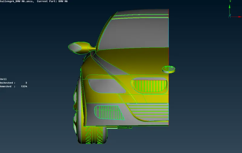
- First, we need to refine the geometry by increasing the element length of the geometry. To do this go to Mesh mode and click length in the parameter menu. Then enter 1 mm as the length of element to refine the geometry of the whole car.
- Click on the macros button adjacent to the cross hatches button. Click universal delete, then hold and drag the mouse around all the leftover design lines to select it. Then click the middle mouse button to finalize the selection and click ok to delete.
- Now isolate the body of the car by using I not button and lock it.
- Click cut in the faces menu and cut the surface into a small surface by selecting two suitable nodes as shown above. Delete the newly created small surface. Then create the perfect surface by clicking new in the faces menu.
- Now we will rectify the errors shown in the below images. Use project from the cons menu to project the single cons to the desired surface. Now use extend option from the faces menu and click on the con which you want to extend. Then click the middle mouse button and select the face.
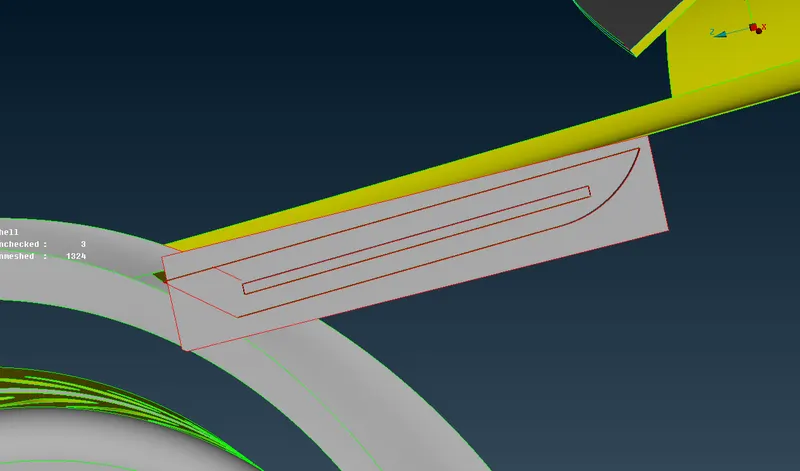
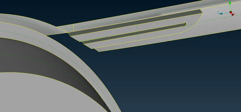
- In the below error, we have to intersect all the faces. Click intersect in the face menu and select the first face then the second face, after that click middle mouse button.
Then delete all unwanted protruding surfaces.
BEFORE CLEANUP:
AFTER CLEANUP:
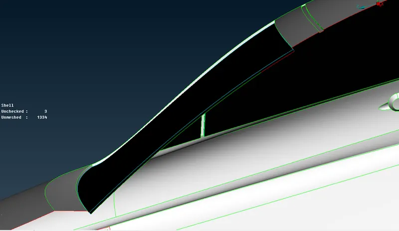
- In the below images, we see that the windows of the car are a volume element, because of this it is causing triple cons. So we have to delete the inner surfaces of the windows.
- Delete all the inner panels of all the windows and the windshield. This will eliminate all the triple cons between the body and windows.
BEFORE CLEANUP:
AFTER CLEANUP:
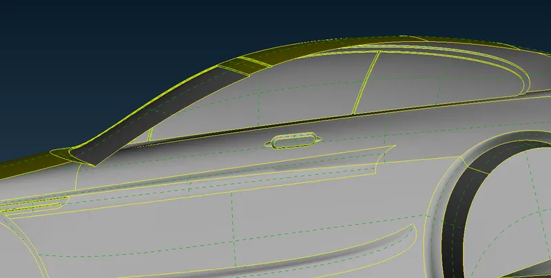
- Now we will rectify the error at the side air vent.
- First, we have to delete the overlapping surfaces, which can be seen in the image above.
- After deleting the overlapping surfaces delete the surface which is covering the complete back of the air went.
- After that delete all the thin wall of the fin which is selected in the above image
- After removing all the overlapping surfaces and single cons we will get the final result as shown in the below image.
BEFORE CLEANUP:
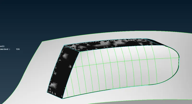
AFTER CLEANUP:
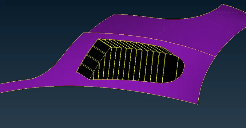
- This is the lower middle air intake vent. There are a lot of errors that we need to take care of at this location.
- First, delete the overlapping surfaces which can be easily seen due to the glitches in the geometry.
- And then release any triple cons by using release option. After that paste the cons to the desired surface.
- There are many surfaces that are not properly aligned at this location. Just delete the surface and recreate it.
- After rectifying all the errors we will get the final result as shown in the below images.
BEFORE CLEANUP:
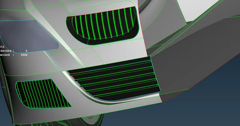
AFTER CLEANUP:
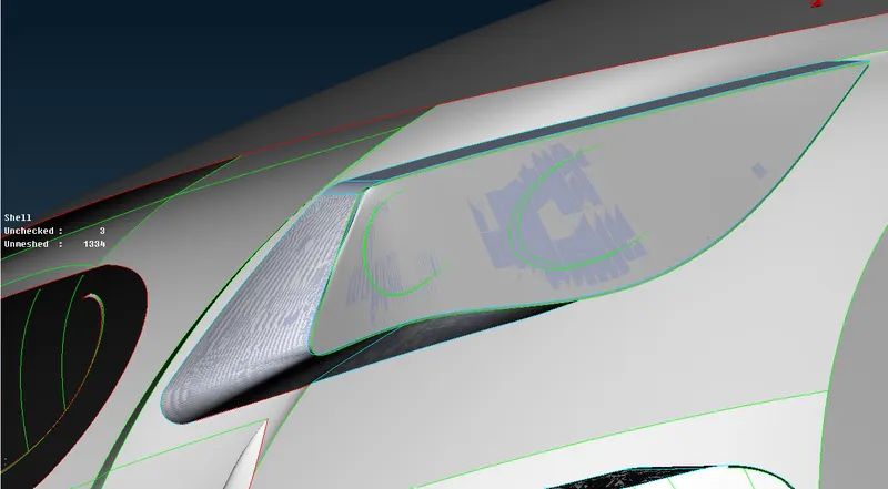
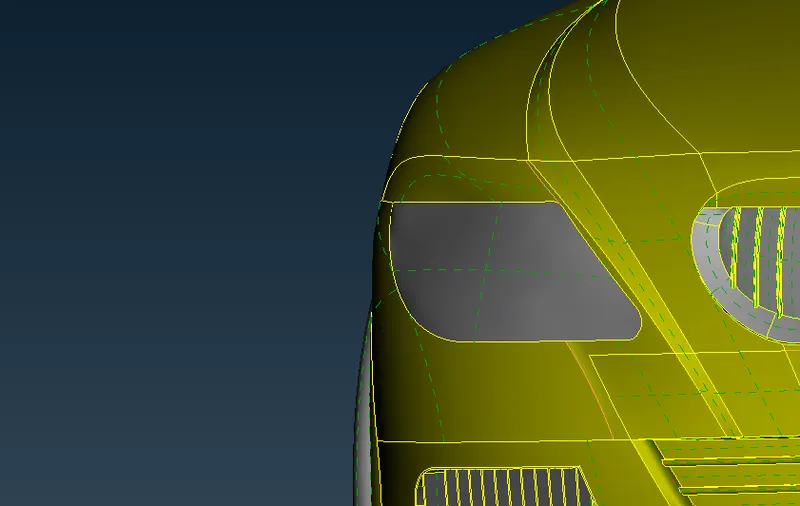
- Now we will take care of headlight. As we can see it has an inner shell that is creating a close volume element.
- We do not need the inner shell of the headlight in external flow aerodynamics.
- So we have to delete the inner shell of the headlight. This will also remove the triple cons which we can see in the below image.
BEFORE CLEANUP:
AFTER CLEANUP:
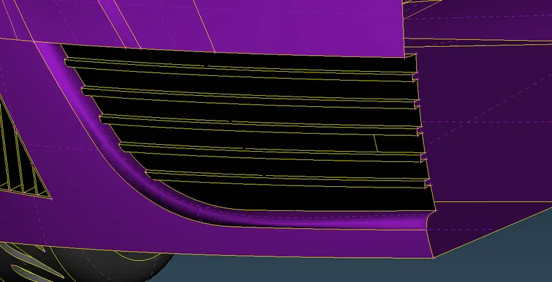
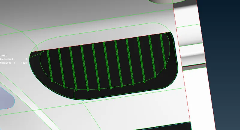
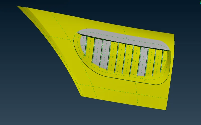
- Now the upper front grill of the car. As we can see that there lot of errors in this part.
- First, we can see that there are overlapping surfaces. We can simply use the universal delete option to delete the overlapping extra surfaces.
- After that, we have to delete the thin surface covering the fins of the air intake grill.
- Then create the new surface to cover all the open faces which we deleted. in this way, all the error will be removed from the upper grill
BEFORE CLEANUP:
AFTER CLEANUP:
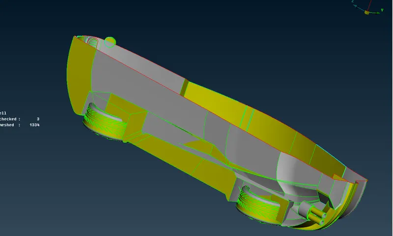
- Now we will work in the lower portion of the chassis and near the wheel cavity.
- At the wheel cavity, we can see that there are some extra surfaces. We have to remove those surfaces.
- To delete those surfaces first we need to intersect the two surfaces by using intersect option to create a separate surface that can be deleted. And then delete protruding surface.
- At the bottom surface of the car, there are a lot of irregular surfaces and overlapping surfaces. Simply delete the extra surfaces and create the new surface to rectify all the errors.
- After removing all the surface errors from the bottom of the chassis and the wheel cavity we will get the final result as shown below in the image.
BEFORE CLEANUP:
AFTER CLEANUP:
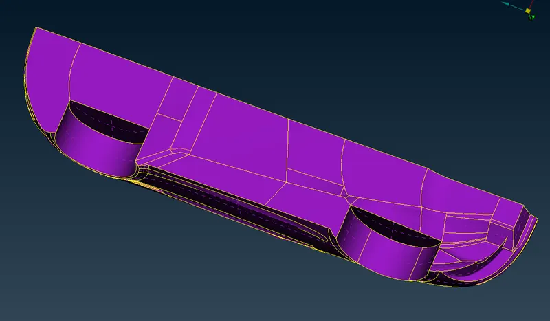
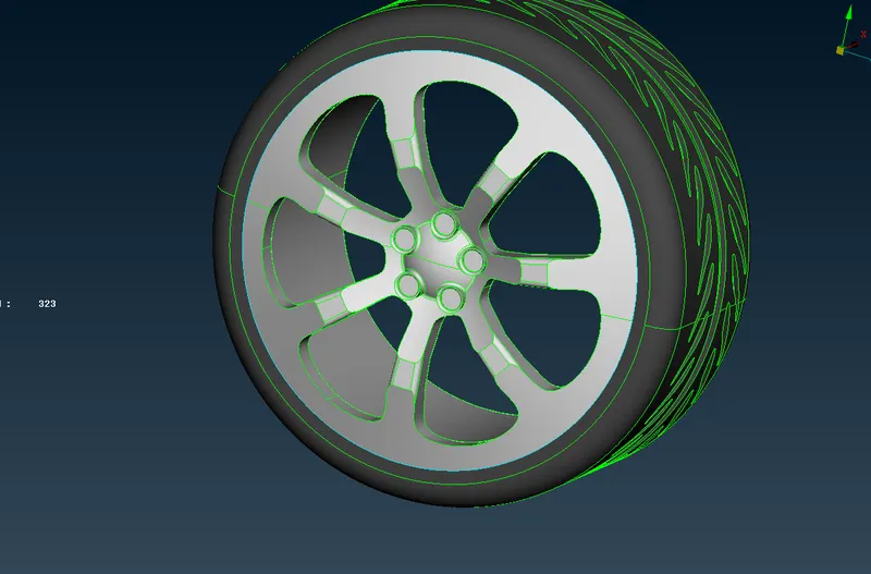
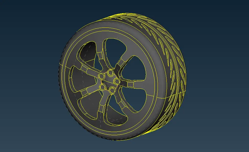
- Now we rectify the errors at the wheels. As we can see that the front right wheel is completely destroyed and almost impossible to recover. So we will use the symmetry feature to copy the wheel from the left side to the right side. So we simply delete the front right wheel.
- Now we will use the alignment of the wheels by using function keys F1 and F2 to properly orient the view of the car.
- Now we will remove all the triple cons from the wheel. These triple cons are due to the extra surfaces between the rim and rubber tires. After deleting the extra surfaces between the tire and rims, these triple cons disappears.
- Now we mirror the front left wheel to the right. To do this, use the transform option and then click copy. After that select the entity option.
- Now left-click and drag the mouse around the object to be copied. Then choose the
symmetry option. In symmetry, window choose mirror 3 point plane. After that choose 3 points on the body of the car along the line of symmetry, all the chosen points should be in three different lines. If all the points are on the same line then symmetry function will not give the desired result. - After selecting three points click the middle mouse button. This will create the new wheel at the front right location of the car.
BEFORE CLEANUP:
AFTER CLEANUP:
2. PID:
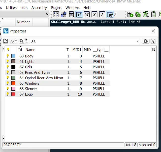
- Now we will assign the name to all the PIDs. In our file, all the PIDs have the default name. So to properly identify them we will assign name PIDs to all the parts.
- To do this, open properties and then click the magnifying glass icon in the search bar as shown in the above image. Then choose visible from the options.
- Then select different PIDs and name them according to the different parts.
3. GEOMETRY CHECKS:
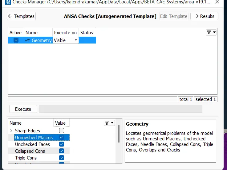
- After all the error rectification run the geometry checks by clicking the checks button and choose geometry option from the list.
- Then select the required checks parameter and execute the check.
- After the execution, the check manager will give some checks. Make visible all the errors one by one and rectify the errors by using suitable tools.
4. SURFACE MESH:
Element length parameters
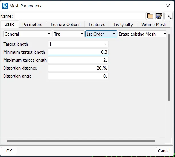
Mesh parameters
Mesh quality criteria
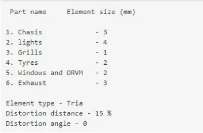
- Now, will set the element length for the mesh elements. All the element lengths are given above, there are different element lengths for different parts.
- To set the element length, click length in perimeters menu and then select the edge of the respective geometry to set the length. Then click the middle mouse button to set the length parameters.
- Follow the above step to set the element length for all the other geometries.
- After setting element length go to mesh parameters then set the mesh parameters. The mesh parameters are given in the above image.
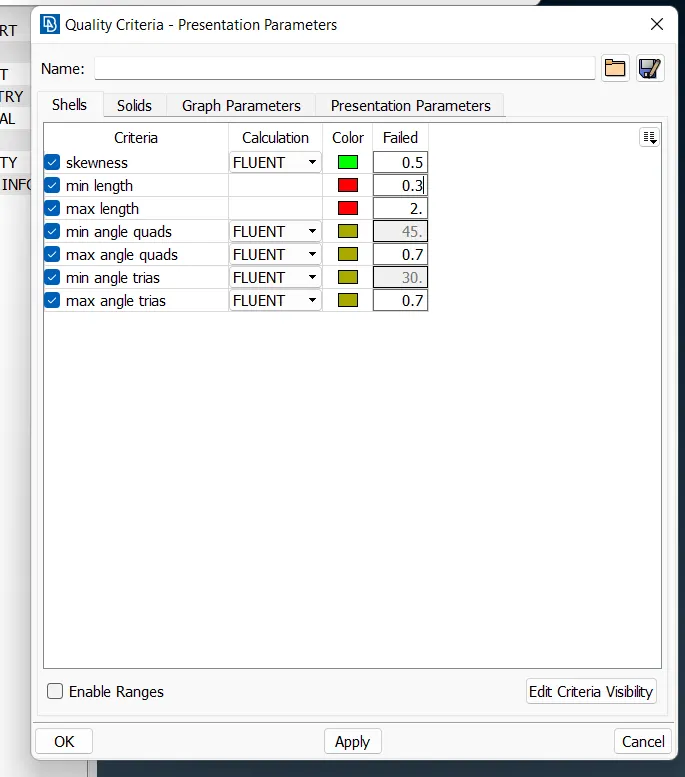
- After setting mesh parameter quality criteria and set the quality criteria of the mesh.
- All the quality criteria for the mesh is given in the above image.
- Then click on the free button in the mesh generation menu to generate the mesh. First, hold and drag left mouse click on the complete geometry to mesh. Then click the middle mouse button to generate the mesh.
5. MESHING:
- After defining element length, mesh parameters and mesh quality criteria we can start mesh generation.
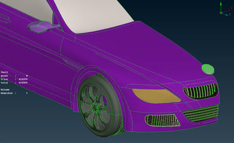
- To mesh the entire geometry, click on free mesh in the mesh generation menu and select the entire geometry of the car. Then click the middle mouse button and this will create mesh on all the surfaces.
HIDDEN MODE
- Now we will enable hidden mode by clicking hidden-button adjacent to the shadow button.
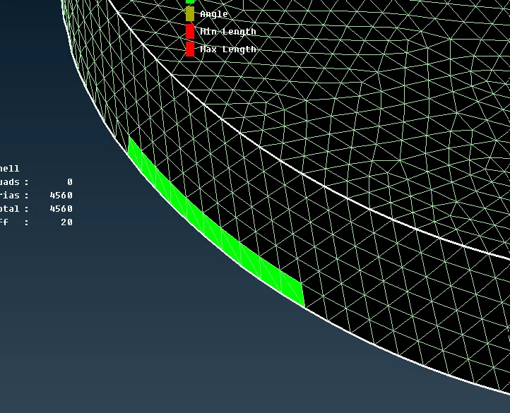
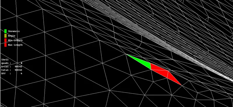
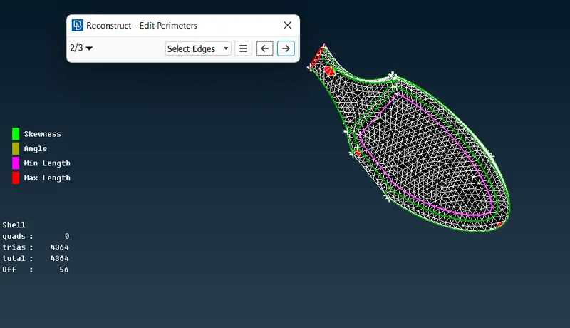
- The hidden mode will reveal several errors according to the parameters set in mesh quality criteria, now we have to remove all the errors according to these quality criteria.
- It is very difficult to rectify all these errors, but we can reduce a large number of errors by using reconstruct option in the shell mesh menu. Reconstruct will remove the majority of the errors but not all of them.
- Above is the image of errors for mesh quality criteria. The red color indicates minimum length error and green color indicates skewness error.
- Minimum length errors can be removed easily by reconstruct option in the shell mesh menu, it will simply reconstruct the mesh according to the mesh quality criteria.
many of the skewness errors will be removed by reconstruct tool but the remaining errors have to removed manually one by one using suitable tools. - To remove skewness error one by one we can use the MV Surf tool in the grids menu and Split tool in the Elements menu.
6. MIRRORING THE MODEL:
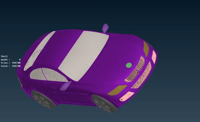
- Now we will mirror the model to complete the geometry
- Go to topo mode and click on the transform button and select copy, then select entities in the pop-up window.
- Then hold and drag the left mouse click to select the complete geometry. And click the middle mouse button.
- After this choose three points with at least one point, not in the same line. After selecting three points
- click the middle mouse button. This will create the complete geometry of the car. The final result is shown in the image above.
7. WIND TUNNEL
Wind Tunnel Dimensions
Inlet - 4*L From front of the car
Outlet - 6*L From Rear of the car
Top Wall - 3*L From Top of the car
Bottom Wall - Close Proximity With Tyres
Side Wall - 1*L From Centre Plane of the car
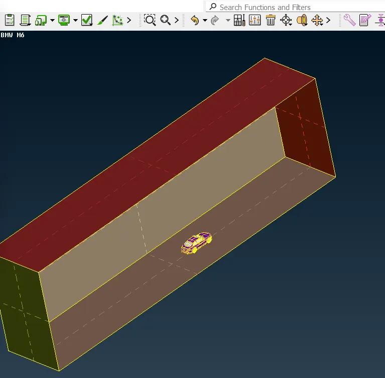
- Now we have to create a wind tunnel for external flow analysis. The dimensions of the wind tunnel are given above.
- Create a point by using the relative option in the points menu. Click on the surface from which you want to measure the distance for the wall, now click the middle mouse button.
- Then enter dz = 4*L for the inlet wall.
- Now connect the newly created point with a curve by using the new option in the curves menu.
- Repeat the above steps to make points at all the required locations.
- After that, we have to create the walls for the wind tunnel at these reference points created.
- To create a surface we need at least three points, so we have to create two more points near the points created earlier at all the six sides of the car.
- To create two additional points use relative option and create the new points at close proximity of the old point.
- We can now create planes at all six sides of the car with the help of these three points.
- To create a plane use plane option in the surfaces menu and select these three points at one side of the car and then click the middle mouse button to create the plane. Use the mouse to adjust and finalize the plane.
- Repeat the above steps to create the planes at all the remaining sides of the car. In this way, a wind tunnel will be created in which we can generate volume mesh for our external flow analysis.
8. WIND TUNNEL SURFACE MESH:
- Now we will define the element length for meshing the wind tunnel.
- For inlet and outlet walls we will use gradually increasing element size. as we do not need very high accurate results at the top wall that is why large element size will be suitable for the simulation and this will save the computational time also.
- To create gradually increasing element use spacing option in perimeters menu and enter the length parameters as follows:
dmin - 20, dlimit - 100 and scaling factor - 1.1, then click ok. - For bottom wall use element size as 20 mm and for top wall set element size as 100mm. Then use the free mesh option in the mesh generation menu and create the surface mesh.
Final Output File Link: https://drive.google.com/file/d/1w46CGg-DCzswiZh8vtdBqwtHuA_iB9Z2/view?usp=sharing