Week 4 Challenge
1ans:
AIM : To Calculate dead load in design report based on IS code and apply dead load on the model.
TOOLS USED :
- Load
- Load cases
- Dead load
- Imposed load
- Area
- Full UDL
- Line
CALCULATIONS :
DEAD LOAD :
Slab load = Model slab in software.
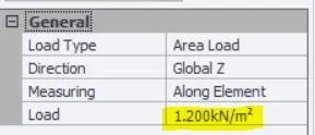
Finishes loading (50THK) = 0.05m x 24 KN/m^3 = 1.2 KN/m^2.
Brickwall with cement plaster thickness = 150mm.
Unit weight = 20 KN/m^3
Floor height (GF to FF) = 5.2 m
Brickwall loading = 15.6 KN/m
Floor height (FF to Roof) = 6.8 m
Brickwall loading = 20.4 KN/m
Roof loading = 1.5 KN/m^2
PROCEDURE :
- First open the file which we created earlier.
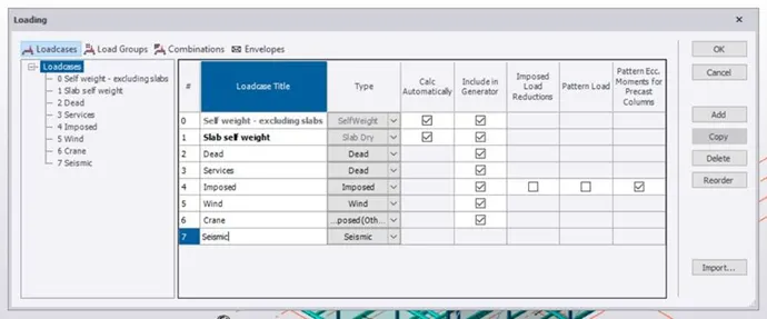
- Go to load tab and select load cases option under that.
- Load cases dialog box appears.
- Create new load such as crane, seismic and wind load to the list of predefined loads.
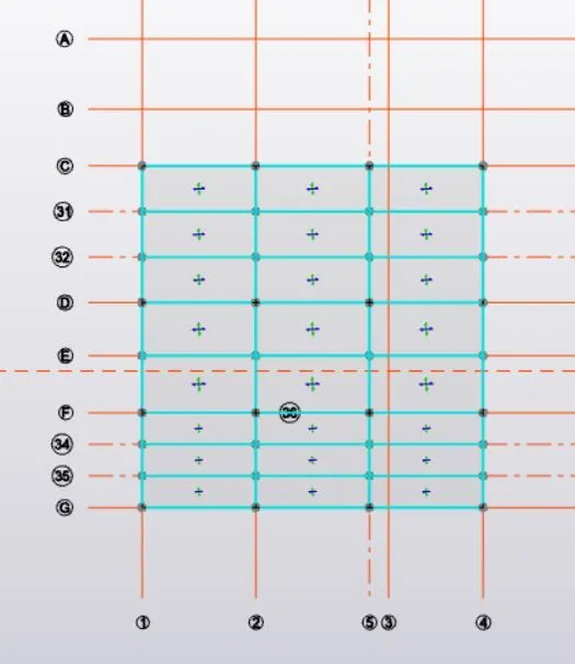
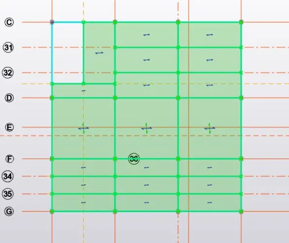
- Now we have to create slabs for all the layers required.
- Based upon the dimension of the adjacent beams we have to select one way or two way slabs.
- Then at the bottom we have to select dead load in the drop up dialog box.
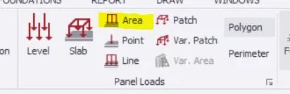
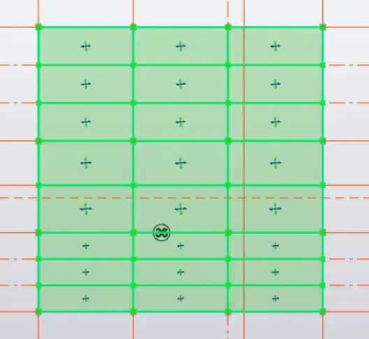
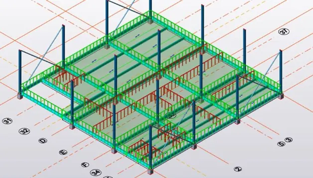
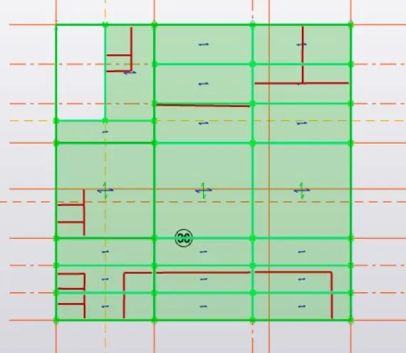
- Under load tab we have to select area and give the value of 1.2KN/m square, and select all the slabs.
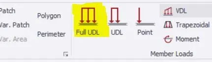
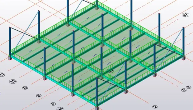
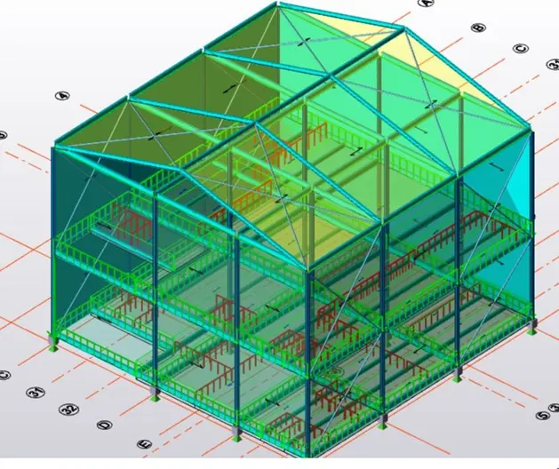
- Next we have to select Full UDL and apply the dead load to all the beams.
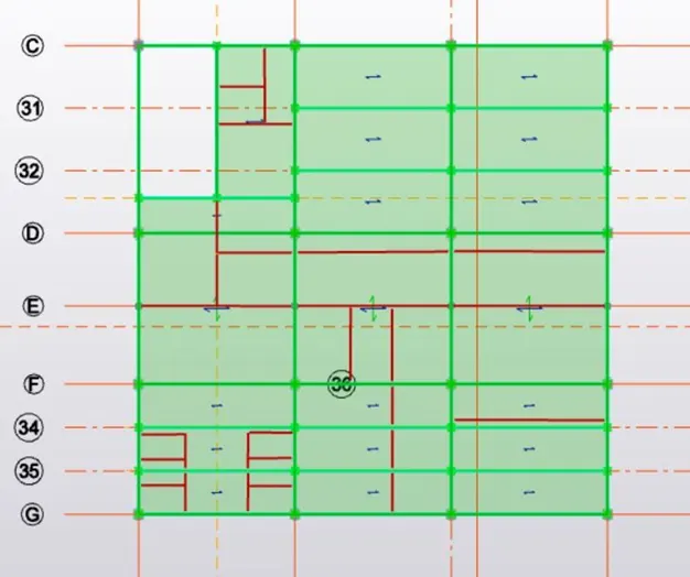
- Next select Line tool under load tab and draw the walls load in all the required floors.
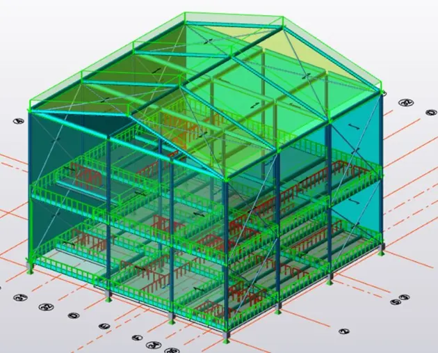
- With this we will be successful in provinding the dead loads to the structure.
- At last click on validate to check whether there are any errors.
-
RESULT :
-
With the above steps we will be able to provide the dead loads to the slabs and beams of our structure.
ANS 2)
AIM : To calculate live load in design report based on IS code and apply live load on the model.
TOOLS USED :
- Load
- Load cases
- Dead load
- Area
PROCEDURE :
- Open the file in which the dead loads were added.
- Next at the bottom select imposed load in the drop up box.
- Now we can provide the live loads to the structure.
- Click on loads and select area option.
- Now under the property dialog box enter the required load for different room.
Store room = 5 KN/m^2
Office = 3 KN/m^2
Rest room = 2 KN/m^2
Toilets = 2 KN/m^2
Pantry = 3 KN/m^2
Corridor = 4 KN/m^2
Equipement room = 10 KN/m^2
- Now set the loads with different values and apply them by clicking on the slabs.
- With this we will be able to provide live loads to the structure.
- Repeat the same process for all the remaning levels.
The live loads for the structure can be obtained from the IS building standard codes.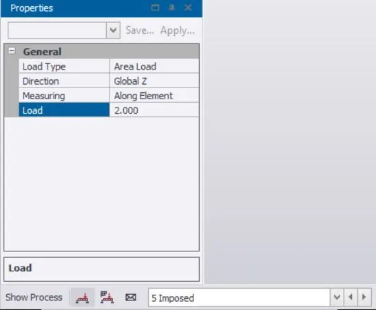

RESULT :
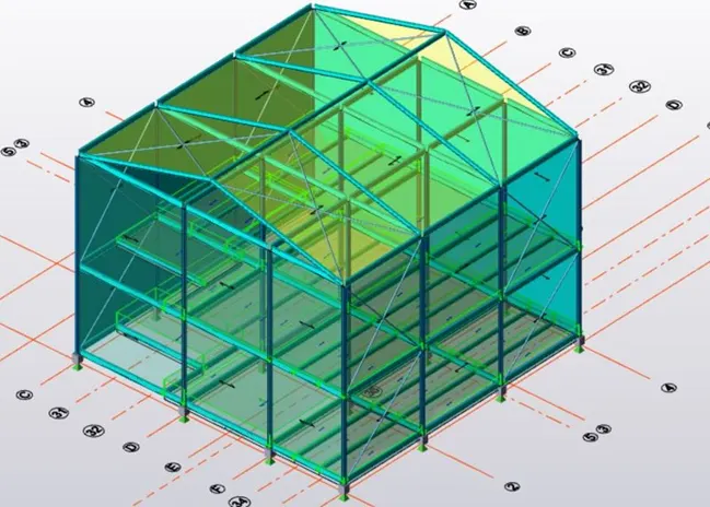
With the above following steps we can apply live loads to the structure and calculate. At last we have to validate and check whether any errors are there, if there are any we have to resolve them as soon as possible.
3ans:
Max wheel load
Maximum concentrated load on crane = 50 + 10 = 60 KN.
Self-weight of crane will act as uniformly distributed load of intensity
=40 / 10 = 4 KN/m.
Taking moment about B :
Ra x 10 – (60 x 9)- (4 x 5 x 10) = 0
10 Ra = 740.
Ra = 74 KN.
Rb x 10 –(60 x 1)-(4 x 10 x 5) = 0
10 Rb = 260
Rb = 26 KN.
Ra + Rb = 100 KN.
The reaction from the crane girder is distributed equally on two wheels at the end of the crane girder.
Maximum wheel load on each of the crane wheel = 74 / 2 = 37KN.
MAXIMUM BENDING MOMENT :
Assume self-weight of the gantry girder as 1.5 KN/m
Total dead load = ( Self-weight of rail + self-weight of gantry girder ) 300 + 1500 = 1800 N/m
Taking moment about D
Rc x 5.5 –(37 x 4.25)- (37 x 2.25) = 0
Rc x 5.5 = 240.5
Rc = 240.5 / 5.5
Rc = 43.72 KN.
Rd x 5.5 – (37 x 1.25)- (37 x 3.25) = 0
Rd x 5.5 = 166.5
Rd = 166.5 / 5.5
Rd = 30.27 KN.
Bending moment under wheel due to live load = Rd x 2
= 30.27 x 2
= 60.54 KN.
Bending moment due to impact = 0.10 x 60.54 ( 10 % increase due to MOT)
= 6.054 KNm
Total bending moment due to live load and impact load = 60.54 + 6.054
= 66.594 KNm.
Bending moment due to dead load = W x l x l / 2
= 1.8 x 5.5 x 5.5 / 2 = 27.22 KNm
Maximum bending moment = 66.594 + 27.22
= 93.814 KNm.
MAXIMUM SHEAR FORCE :
For maximum shear force, one of
Rc x 5.5 –(37 x 5.5)-(37 x 2.5) = 0
Rc = 9.25 + 20.35 / 5.5
Rc = 5.381 KN
The maximum shear force due to wheel load = 5.31 KN
LATERAL FORCES :
Lateral forces traverse to rails = 5% of the weight of crab and weight lifted
= 0.05 ( 40 + 10 )
= 2.5
Lateral forces on each side wheel F1 = 2.5 / 2 = 1.25 KN
Maximum horizontal reaction due to the lateral force by proportion at C
= Lateral force x reaction at C due to vertical load / maximum wheel load due to vertical load
= 1.25 x ( 43.72 / 37) = 1.44 KN
At D
2.5 – 1.44 = 1.06 KN
Bending moment due to lateral load by proportion
= (1.25 / 37) x 5.31
= 0.179 KNm.