Week 2 Challenge
1ans) BIM stands for Building Information Modeling. It is used for the planning, design, construction, and management of building and infrastructure projects. BIM software is used to model and optimize projects by planning, designing, building, and operating BIM models.
BIM provides the opportunity for construction teams and consultants to maximize time and money, limiting any resulting friction in a project.Time saving is one main reason we can use bim.if we change only one side in bim all the gets changes but in cad we cant because its 2D.
2ans)
Aim:To use insert Tab and choose a category, Pick a family and element and Understand the instances and insert it to Revit model
Tools used:
1. insert tab
2. load family
3. component
4. property browser
Procedure:
1)Go to insert from tool bar
2) Click on load family from import section
3) from the dialog box select the requiered family to be loaded
4) from architactural menu click component to use the model elements selected from insert
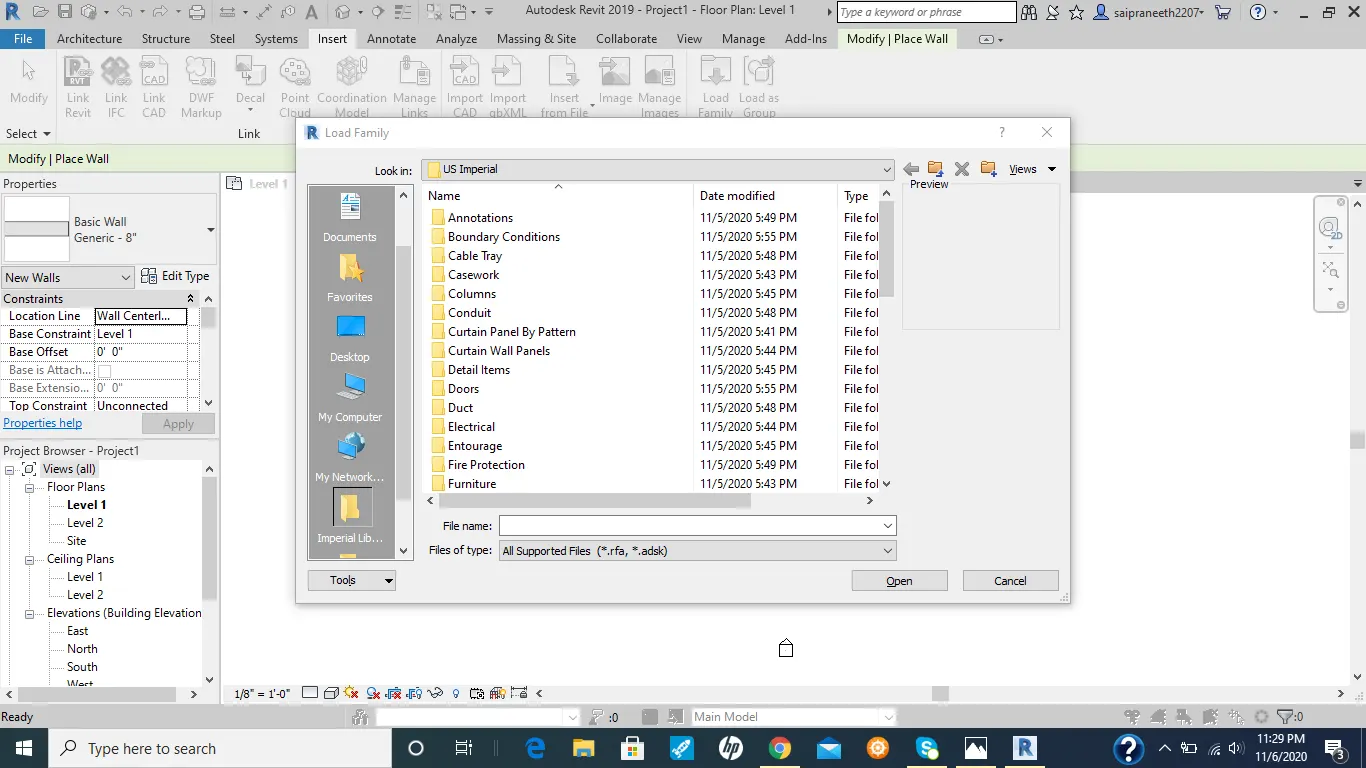
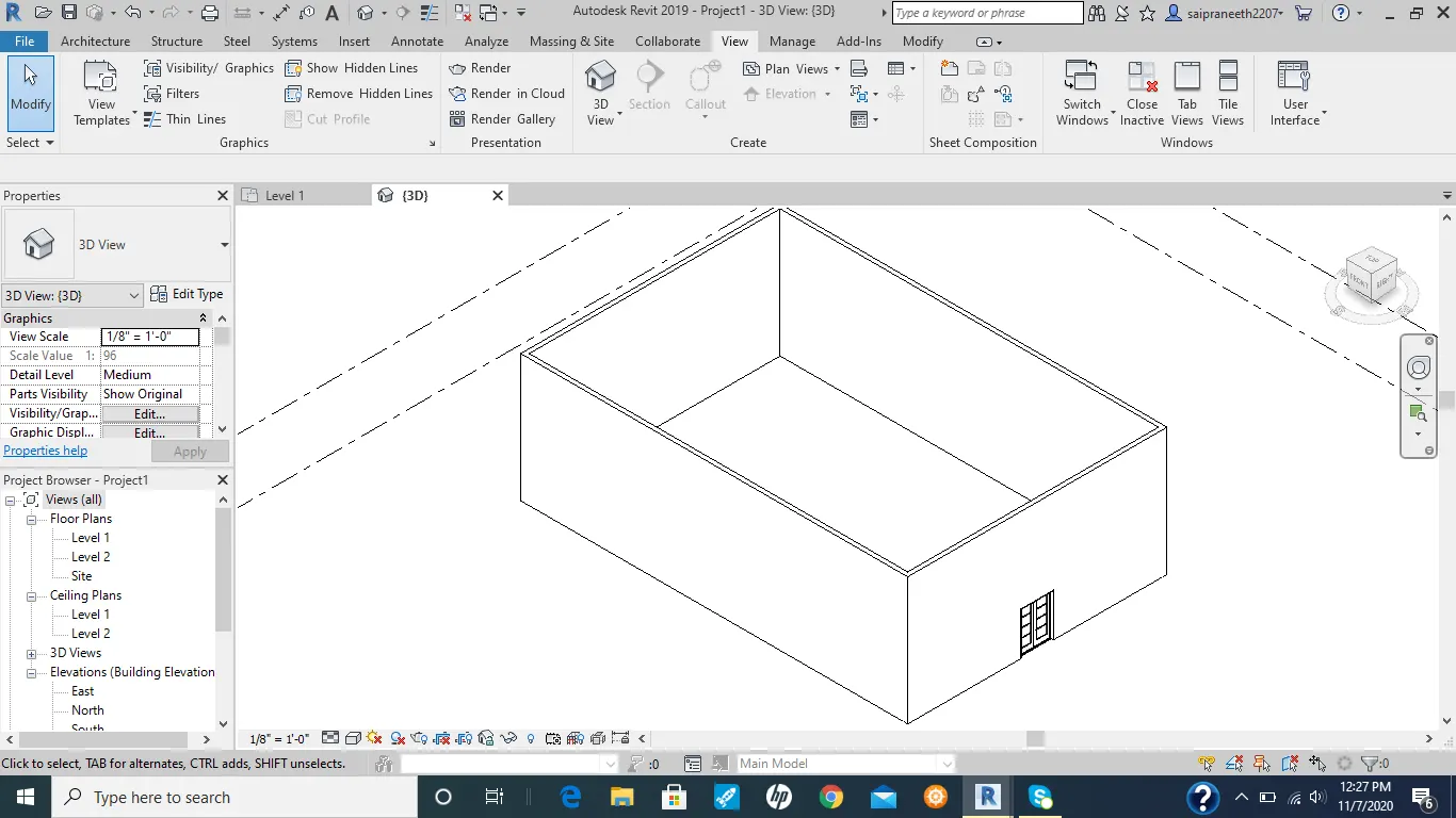
Result:An element was inserted.
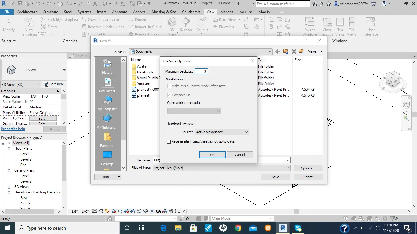
3ans)Aim: To open a project file with an architectural template. To save the file with an appropriate name. To set up the project units to Imperial / Metric based on your convenience of modeling and complete the project information under the Manage tab. At last set up the maximum backups for the project file to 3.
tools required:file,manage tab,project information and project tab
procedure:
- Open revit 2019, click on new option.
- Select architectural template and click on ok.
- Click on file menu and select save as option and click on project.
- Save as dialog box appears, give a name to the project and save it.
- Click on manage memu and change the project units to imperial/metric
- Click on project information and fill in the details.
- At last set the maximum backups to 3.
result:
We can open a project in architectural template and save it with a appropriate name having 3 backups of the project. We can change the project units and fill in the project information with the above steps.
4ans)
Aim:To understand the concept of Levels and Grids and create the following Levels: ( Convert to metric equivalents if metric is your units) Ground Floor @ 0’ First Floor @ 10’
Second Floor @ 20’ Roof @ 30’
Grids Transverse Grids A, B,C,D, E @ 10’ spacing Longitudinal Grids from 1 to 10 @ 20’ spacing
Tools used:
1)level
2)Grid
Procedure:
1)From the architecture menu in the datum section click on a level to ad levels
2) to ad levels one must open an elevation view
3)Enter the desired distance below the label where the distance between levels is shown to change the distance
4)From the architecture menu in the datum section click on the grid to ad grids
5)horizontal grids are tagged with alphabets and vertical with numerical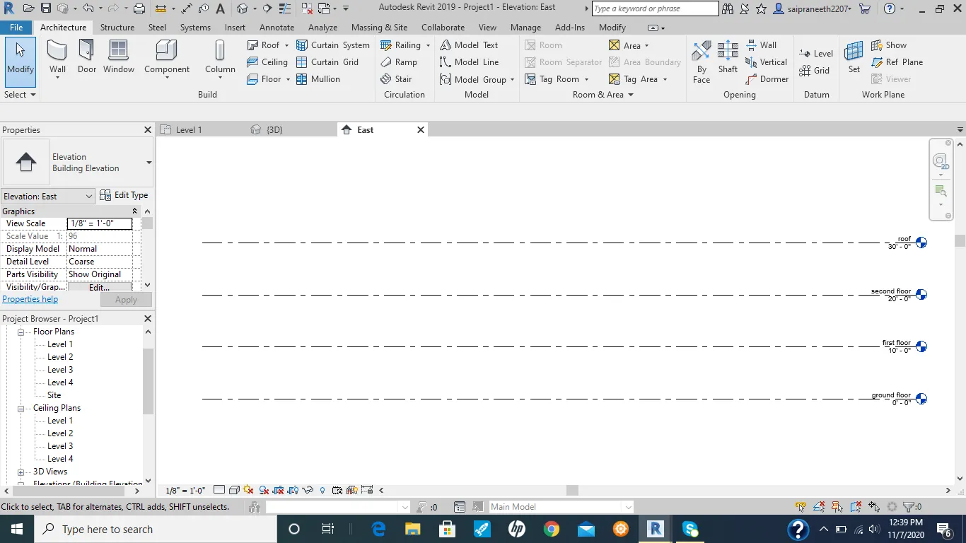
Result: Given grids and levels were made by using Revit.
5ans)aim:
3D modeling of a residential house, to create a conceptual layout of the residential unit.
tools required:
Architecture.Wall.View.Default 3D view.
procedure:
- Open revit and select architectural template and click on ok.
- Select wall tool from architecture menu and click the curson on the drawing space where you want to start your project.
- After drawing one side repeat the same process for the remaining sides with the desired dimensions.
- At last we can join the end of the fourth side to the starting point so as to obtain a closed figure.
- Next click on the view menu and select the Default 3D view option.
- The required layout appears in 3D view.
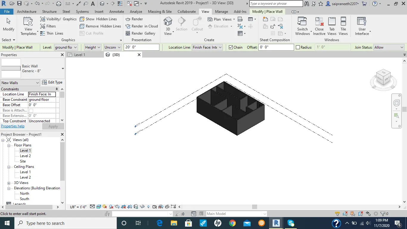
result:
Thus by following the above mentioned steps we can draw the required layout in 3D view.
6ans)aim:In the layout created draft the level of details you are planning to include – Dimensions of room, components you plan to add in the residential unit.
procedure:
1) select walls, from properties browser change wall to interior wall
2)mark the walls as desired and make rooms
3)from the architecture menu in from room and area section select room
4)click on closed interior spaces to name them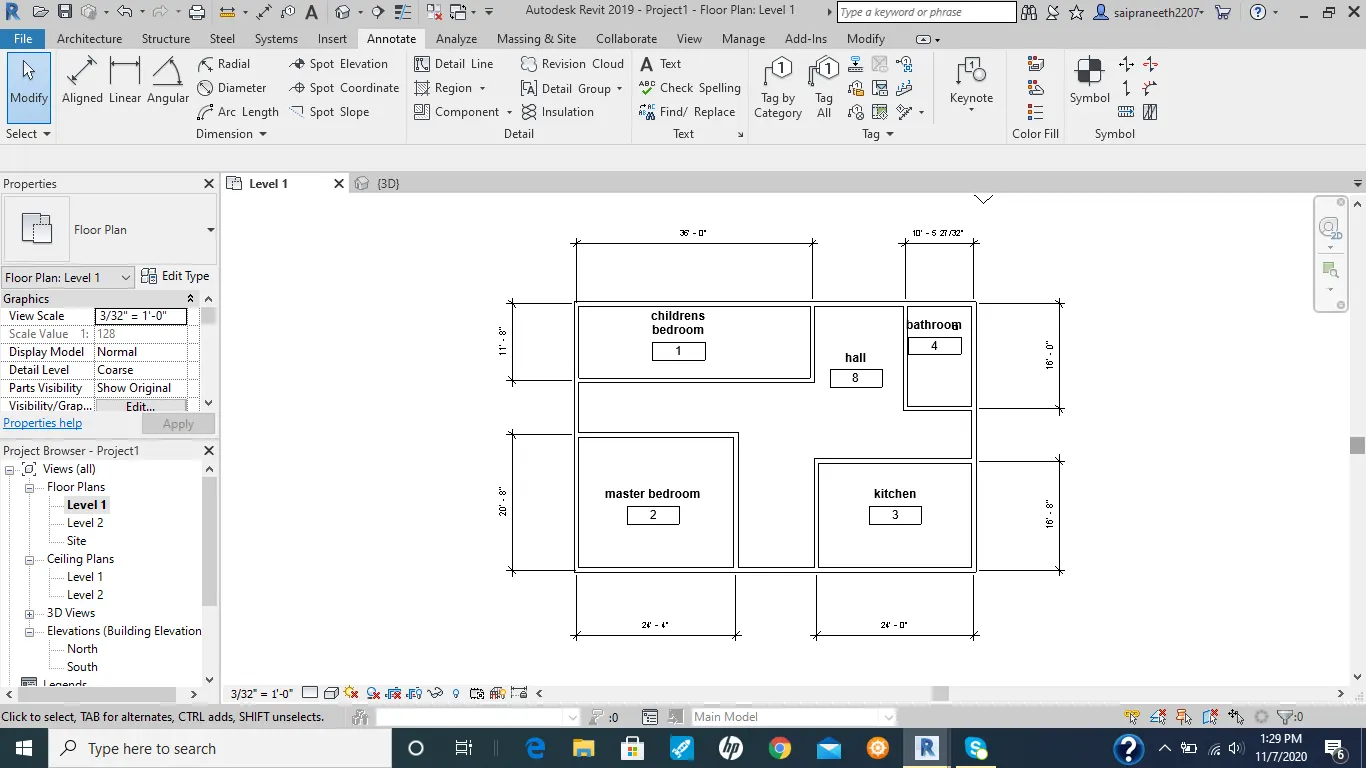
result:drafting is completed in the layout created.
7ans)aim:
To add components to the layout project like doors, windows, tables, chairs, couch, bed, lamps from the insert library.
tools used:insert,furniture,doors,windows,beds,sofa,dining table,wadrobe.
procedure:
- After we complete the inner walls and dimensioning we have to start with the interiour components.
- From insert menu with the help of load family we have to load the components like windows, doors and other componets like table, sofa, beds ets.
- With the help of default 3D view option from the view menun we can convert the project into 3D view.
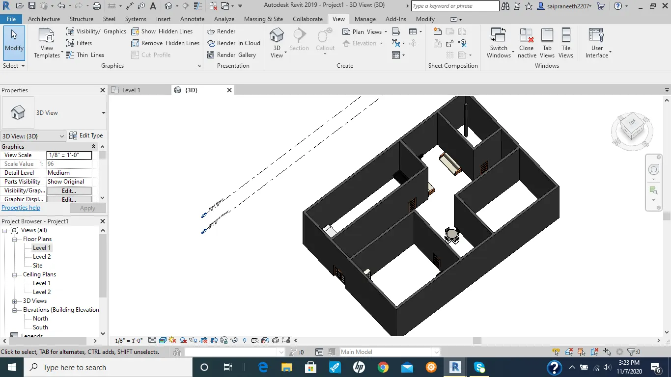
result:
With the above steps we can successfully add the components to the project like doors, windows and other components.